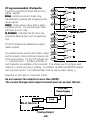
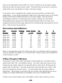
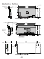
1
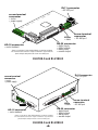
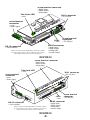
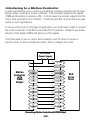
User’s Manual
BLU Series
Digital Servo Drives
BLU100-D
BLU100-S
BLU100-Si
BLU200-D
BLU200-S
BLU200-Si
motors • drives • controls
-2-
Contents
Introduction ................................................................................................................................................. 4
Features ....................................................................................................................................................... 4
Block Diagram ............................................................................................................................................. 4
Getting Started ............................................................................................................................................ 5
Connecting to the PC using RS-232 ......................................................................................................... 8
Connecting to a host using RS-485 .......................................................................................................... 9
Getting an RS485 adaptor for your PC ............................................................................................ 10
Connecting the Power Supply ................................................................................................................. 11
Connecting the Motor .............................................................................................................................. 12
Connecting Input Signals ........................................................................................................................ 13
BLU-D and BLU-S Inputs ................................................................................................................. 13
BLU-Si Inputs .................................................................................................................................... 13
Connector Pin Diagrams .................................................................................................................. 13
High Speed Digital Inputs ................................................................................................................. 14
Using High Speed Inputs with 12-24 Volt Signals ................................................................................ 15
Connecting to PLC with Sourcing (PNP) Outputs .......................................................................... 16
Connecting to PLC with Sinking (NPN) Outputs ............................................................................. 16
Using Mechanical Switches at 24 Volts. .......................................................................................... 16
Other Digital Inputs .................................................................................................................................. 17
Single Ended Inputs ................................................................................................................................ 17
What is COM? .................................................................................................................................... 17
Connecting Limit Switches to the BLU Drives ........................................................................................ 19
Wiring a Mechanical Limit Switch ........................................................................................................... 20
Wiring a Limit Sensor .............................................................................................................................. 20
Wiring a Mechanical Limit Switch ........................................................................................................... 21
Wiring a Limit Sensor .............................................................................................................................. 21
Interfacing to a Motion Controller ........................................................................................................... 23
Connecting to the Si™ Analog Input ...................................................................................................... 24
Programmable Outputs ........................................................................................................................... 25
Sinking Output .................................................................................................................................. 25
Sourcing Output ................................................................................................................................ 26
Driving a Relay .................................................................................................................................. 26
Encoder Outputs ....................................................................................................................................... 26
Choosing a Power Supply ....................................................................................................................... 27
Voltage ............................................................................................................................................... 27
Current ............................................................................................................................................... 27
Recommended Motors ............................................................................................................................. 28
Other People's Motors ............................................................................................................................. 28
Mounting the Drive .................................................................................................................................. 29
BLU100-D and BLU100-S ................................................................................................................ 29
BLU100-Si ......................................................................................................................................... 29
BLU200 (all models) ......................................................................................................................... 29
Mechanical Outlines ................................................................................................................................. 30
Technical Specifications .......................................................................................................................... 32
Alarm Codes ............................................................................................................................................. 34
Connector Diagrams ................................................................................................................................ 34
-3-
Introduction
Thank you for selecting an Applied Motion Products motor control. We hope our
dedication to performance, quality and economy will make your motion control
project successful.
If there's anything we can do to improve our products or help you use them better,
please call or fax. We'd like to hear from you. Our phone number is (800) 525-1609
or you can reach us by fax at (831) 761-6544. You can also email [email protected].
Features
•
•
•
•
•
•
•
•
Digital servo motor driver in compact package
Operates from 24 to 48 volt DC power supply
Operates in torque, velocity or position mode
Accepts analog signals, digital signals and RS-232/485 serial commands
Motor current to 13.5 amps peak, 4.5 amps continuous (9A cont. with BLU200)
Seven optically isolated digital inputs (15 inputs on -Si)
Three optically isolated digital outputs (7 outputs on -Si)
±10 volt analog input for speed and torque control
Block Diagram
24 - 48 VDC
X1/STEP/PWM
X2/DIR
X3/SVEN
X4/ALMRST
X5
X6/CCWLMT
X7/CWLMT
Internal
Logic
Supply
Optical
Isolation
to RS-485 host
motor
encoder
ANALOG+
ANALOG–
to PC
MOSFET
PWM
Power
Amplifier
DSP
RS-232
Line
Drivers
Optical
Isolation
RS-485
-4-
ENCODER OUT
Y1/BRAKE
Y2/INPOSN
Y3/ALARM
Getting Started
This manual describes the use of six different drive models. What you need to know
and what you must have depends on the drive model. For all models, you must
have the following:
• a 24-48 volt DC power supply for the motor. Please read the section entitled
Choosing a Power Supply for help in choosing the right power supply.
• a compatible servo motor
• cables to connect the motor to the drive. If you are using an Applied Motion
“Alpha” motor, use BLUENC and BLMTR cables (one of each).
• a small flat blade screwdriver for tightening the connectors (included).
• a personal computer running Microsoft Windows 95, 98, NT, Me, 2000 or XP.
• The Applied Motion “Si™” CD (included)
• An Applied Motion Si™ programming cable (included)
If you’ve never used a BLU ser
vo before, you’ll need to get familiar with the drive
servo
and the set up software before you try to deploy the system in your application. We
strongly recommend the following:
1.
2.
3.
4.
5.
6.
7.
Install the Quick Tuner software from the CD.
Launch the software by clicking Start...Programs...Si Programmer...Quick Tuner.
Connect the drive to your PC using the Si™ Programming cable.
Connect the drive to the power supply.
Connect the drive to the motor.
Apply power to the drive.
Follow the instructions in the Quick Tuner manual.
The connectors and other points of interest are illustrated on pages 6 and 7. Depending on your drive model and application, you’ll need to make connections to various
parts of the drive. These are detailed later in the manual.
-5-
RJ11 connector
• RS-232 port
screw terminal
connector
• motor
• power supply
LEDs
• status
HD-15 connector
• motor feedback
Always use the blue & white Applied Motion screwdriver to tighten
the screw terminal connectors. Larger screwdrivers may remove the
plastic dimples that prevent the screws from falling out.
screw terminal
connector
• RS-485 port
DB-25 connector
• digital inputs
• digital outputs
• analog input
• encoder output
BLU100-S and BLU100-D
RJ11 connector
• RS-232 port
screw terminal
connector
• motor
• power supply
LEDs
• status
HD-15 connector
• motor feedback
Always use the blue & white Applied Motion screwdriver to tighten
the screw terminal connectors. Larger screwdrivers may remove the
plastic dimples that prevent the screws from falling out.
screw terminal
connector
• RS-485 port
DB-25 connector
• digital inputs
• digital outputs
• analog input
• encoder output
BLU200-S and BLU200-D
-6-
screw terminal connector
• digital inputs
• digital outputs
• analog input
Two Color LED
• status
RJ11 connector
• RS-232 port
screw terminal
connector
• motor
• power supply
LEDs
• status
HD-15 connector
• motor feedback
Always use the blue & white Applied Motion screwdriver to tighten
the screw terminal connectors. Larger screwdrivers may remove the
plastic dimples that prevent the screws from falling out.
screw terminal
connector
• RS-485 port
DB-25 connector
• digital inputs
• digital outputs
• analog input
• encoder output
BLU100-Si
screw terminal connector
• digital inputs
• digital outputs
• analog input
Two Color LED
• status
RJ11 connector
• RS-232 port
screw terminal
connector
• motor
• power supply
LEDs
• status
HD-15 connector
• motor feedback
Always use the blue & white Applied Motion screwdriver to tighten
the screw terminal connectors. Larger screwdrivers may remove the
plastic dimples that prevent the screws from falling out.
screw terminal
connector
• RS-485 port
DB-25 connector
• digital inputs
• digital outputs
• analog input
• encoder output
BLU200-Si
-7-
Connecting to the PC using RS-232
• Locate your computer within 6 feet of the BLU servo drive.
• Your drive was shipped with a black adapter plug. It has a telephone style jack at
one end and a larger 9 pin connector at the other . Plug the large end into the COM1
serial port of your PC. Secure the adapter with the screws on the sides. If the COM1
port on your PC is already used by something else, you may use the COM2 port for
the drive. On some PCs, COM2 will have a 25 pin connector that does not fit the
black adapter plug. If this is the case, and you must use COM2, you will have to
purchase a 25 to 9 pin serial adapter at your local computer store.
• Your drive was also shipped with a 7 foot telephone line cord. Plug one end into
the adapter you just attached to your PC, and the other end into the RS-232 jack on
your drive. If you need to locate your drive farther from the PC, you can replace the 7
foot phone cord with a longer one. Do not exceed 50 feet.
Never connect a BLU servo drive to a telephone circuit. It uses the
same connectors and cords as telephones and modems, but the voltages are not compatible.
RX (to PC TX)
ground (to PC ground)
No connection
TX (to PC RX)
Pin Assignments of PC (RS232) Port
RJ11 connector
-8-
Connecting to a host using RS-485
RS-485 allows you to connect more than one drive to a single host PC, PLC or other
computer. It also allows the communication cable to be long (more than 1000 feet).
But the device to which you connect must have an RS-485 port.
Pin diagram and wiring are shown below. We recommend the use of Category 5
cable. It is widely used for computer networks, it is inexpensive, easy to get and
certified for quality and data integrity.
Our RS485 implementation is a multi-drop network with separate transmit and
receive wires. One pair of wires must connect the host computer's transmit signals
to each drive's RX+ and RX- terminals. Another pair connects the TX+ and TX- drive
terminals to the host computer's receive signals. A logic ground terminal is provided
on each drive and can be used to keep all drives at the same ground potential. This
terminal connects internally to the DC power supply return (V-), so if all the drives on
the RS485 network are powered from the same supply it is not necessary to connect
the logic grounds. You should still connect one drive's GND terminal to the host
computer ground. Before wiring the entire system, you'll need to connect each drive
individually to the host computer so that a unique address can be assigned to each
drive. Proceed as follows:
RS-485/422
GND
TX–
TX+
RX–
RX+
1. Connect the drive TX+ to the PC's RX+ terminal.
2. Connect the drive TX- to PC RX-.
3. Connect RX+ to TX+.
4. Connect RX- to TX-.
5. Connect GND to GND.
Apply power to the PC and start the SiNet™ Setup software. Select the proper comm
port (1,2,3 or 4) then apply power to the drive. Press the Caps Lock key. The
drives only accept commands in uppercase. Type RV then press ENTER. If the drive
has power and is properly wired, it will respond with "RV=x". Where x is the
firmware version of your drive. If the drive responds, you're home free: the RS485
network is functioning.
Next, you must choose an address for this drive. Any of the "low ascii" characters
(many of which appear above the number keys on a PC keyboard) is acceptable: ! " #
$%&'()*+,-./0123456789:;<>?@
-9-
To find out what address is in the drive now, type DA then press enter. The drive will
respond with DA=x, where x is the address that was last stored. (For example, the
response might be DA=@ or DA=!). To change the address, type DAy, where y is the
new address character, then press ENTER.
To test the new address, type yRV, then press ENTER. For example, if you set the
address to % and want to test that, type %RV. The drive should respond just as it
does to RV, the global revision level request.
Once all the drives have been assigned unique addresses, you can proceed to wire
the whole system together.
Getting an RS485 adaptor for your PC
Model 117701 from Jameco Electronics (800-831-4242) works well. This adaptor is
for a 25 pin serial port. If you are like most people and have a 9 pin serial port on
your PC, you will also need to purchase Jameco cable 31721. Connect as follows:
adaptor drive
1
RX+
2
RX3
TX4
TX+
Set the switches for DCE and TxON,RxON. Don't forget to plug in the DC power
adaptor that comes with the unit.
to PC GND
to PC TXto PC TX+
to PC RXto PC RX+
+TX- +RX- GND
+TX- +RX- GND
Drive #1
Drive #2
RS-485 System Wiring
-10-
+TX- +RX- GND
Drive #3
Connecting the Power Supply
If you need information about choosing a power supply, please read Choosing a
Power Supply located elsewhere in this manual.
If you plan to use a regulated power supply you may encounter a problem with
regeneration. If you rapidly decelerate a load from a high speed, much of the kinetic
energy of that load is transferred back to the power supply. This can trip the overvoltage protection of a switching power supply, causing it to shut down. We offer two
“regeneration clamps” that can solve this problem: the RC010 and RC050. If in
doubt, buy an RC050 for your first installation. If the “regen” LED on the RC050
never flashes, you don’t need the clamp.
Connect the motor power supply "+" terminal to the driver terminal labeled "VDC".
Connect power supply "-" to the drive terminal labeled "GND". Use 18 or 20 gauge
wire.
Be careful not to reverse the wires. Reverse connection will destroy
your driver, void your warranty and generally wreck your day.
-11-
Connecting the Motor
Never connect or disconnect the motor while the power is on.
Applied Motion motor:
To connect an Applied Motion servo motor to your BLU Servo, you'll need a set of
mating cables called the BLUENC and the BLMTR.
Connect the small motor connector to one end of the BLMTR cable. The other end of
the BLMTR has lead wires that connect to the drive’s screw terminal connector as
follows:
A = red wire
B = white wire
C = black wire
"-" = green wire
Connect the large motor connector to one end of the BLUENC cable. The other end
of the BLUENC plugs into the BLU servo.
Non-Applied Motion motor:
Connect the motor leads to the screw terminal connector as follows:
A = motor phase A, R or U
B = motor phase B, S or V
C = motor phase C, T or W
"-" = ground wire
The encoder connections use a HD-15 connector, which you must connect to your
encoder as shown below. See back page for mating connector information.
encoder B+ (3)
Hall 1+ (9)
encoder B- (4)
Hall 1-(10)
encoder Z+ (5)
motor RTD (15)
Hall 3- (14)
Hall 3+ (13)
(8) GND
(2) encoder A(7) +5VDC 200mA
(1) encoder A+
(6) encoder Z-
(11) Hall 2+
(12) Hall 2-
Pin Assignments (facing drive)
-12-
Connecting Input Signals
The BLU servo drives have four types of inputs:
• high speed digital inputs for steps & direction or PWM commands, 5 volt logic
• digital inputs for other signals, 12 - 24 volt logic
• analog input for torque and speed commands, ±10V
• analog input for Si™ programs (BLU-Si only), 0 to 5 volts.
BLU-D and BLU-S Inputs
These drives include seven digital inputs and one analog input. The inputs are
programmable on the BLU-S drive.
CW & CCW Limit: can be used to inhibit motion in a given direction, forcing the
motor and load to travel within mechanical limits.
PWM & DIR: digital signal commanding torque or velocity (or position on BLU-S)
Servo Enable: servo is active when closed. Motor is disabled (turns freely) when
open.
Alarm Reset: Close this signal momentarily to reset a drive fault (alarm).
Analog In: analog torque or velocity command signal
BLU-Si Inputs
The BLU-Si adds eight programmable inputs on screw terminal connectors.
Connector Pin Diagrams
Encoder
Outputs
Shared
Common
25
24
23
22
21
20
19
18
17
16
15
14
13
12
11
10
9
8
7
6
5
4
3
2
1
GND
X1/STEP/PWM+
X1/STEP/PWMX2/DIR+
X2/DIRX COMMON
X3/Servo Enable
X4/Alarm Reset
X5
X6/CCW Limit
X7/CW Limit
Analog INAnalog IN+
Front View
DB-25 Connector
Available on all drives
-13-
Shared
Common
A+
AB+
BZ+
ZGND
+5V OUT (200 mA MAX)
Y COMMON
Y3/ALARM
Y2/INPOSN
Y1/BRAKE
OUT1+
OUT1OUT2+
OUT2OUT3+
OUT3OUT4+
OUT4IN1
COM
IN2
IN3
COM
IN4
CWLIM+
CWLIMCCWLIM+
CCWLIMCWJOG
COM
CCWJOG
+5V
AIN
GND
Analog
Input Single Ended Differential
Inputs
Inputs
Single Ended
Inputs
Outputs
Si™ Input/Output Connector
BLU-Si only
High Speed Digital Inputs
12
inside BLU Servo
330
STEP/PWM+
The BLU-S and BLU-D drives include two
11
220 pF
high speed inputs called STEP/PWM and
STEP/PWM330
DIR. They accept 5 volt single-ended or
10
DIRECTION+
differential signals, up to 2 MHz. Normally
220 pF
9
these inputs connect to an external controller DIRECTIONthat provides step & direction or PWM &
direction command signals. You can also connect a master encoder to the high
speed inputs for following applications.
Indexer
with
Sourcing
Outputs
COM
DIR-
DIR
DIR+
STEP-
STEP
BLU
Servo
Drive
STEP+
Connecting to indexer with Sourcing Outputs
Indexer
with
Sinking
Outputs
+5V OUT
DIR+
DIR
DIRSTEP+
STEP
STEP-
BLU
Servo
Drive
Connecting to Indexer with Sinking Outputs
(includes Applied Motion Si-1 Indexer)
-14-
Indexer
with
Differential
Outputs
DIR+
DIR+
DIR-
DIR-
STEP+
STEP+
STEP-
STEP-
BLU
Servo
Drive
Master
Encoder
A+
STEP+
A-
STEP-
B+
DIR+
B-
DIR-
GND
GND
BLU Servo
Connecting to Indexer with Differential Outputs
(Many High Speed Indexers have Differential Outputs)
Wiring for Encoder Following
Using High Speed Inputs with 12-24 Volt Signals
Most PLCs don't use 5 volt logic. You can connect signal levels as high as 24 volts
to the STEP and DIR inputs if you add external dropping resistors, as shown below.
• For 12 volt logic, add 820 ohm, 1/4 watt resistors
• For 24 volt logic, use 2200 ohm, 1/4 watt resistors
The maximum voltage that can be applied to an input terminal is 24
volts DC. Never apply AC voltage to an input terminal.
-15-
+12-24V
PLC
with
Sourcing
Outputs
OUT1
DIR+
R
STEP-
R
OUT2
STEP+
GND
DIR-
BLU
Servo
Drive
Connecting to PLC with Sourcing (PNP) Outputs
(Most PLC's use 24 volt logic)
PLC
with
Sinking
Outputs
+12-24V
DIR+
DIR
DIRR
R
STEP
STEP+
BLU
Servo
Drive
STEP-
Connecting to PLC with Sinking (NPN) Outputs
(Most PLC's use 24 volt logic)
+
+24VDC
Power
Supply
DIR+
direction switch
DIR2200
run/stop switch
(closed=run)
-
2200
STEP+
STEP-
Using Mechanical Switches at 24 Volts.
-16-
BLU
Servo
Drive
Other Digital Inputs
As we mentioned in the previous section, the high speed STEP/PWM and DIR inputs
are configured for five volt logic. All other digital inputs are designed for operation
between 12 and 24 volts DC. This includes five inputs on the main board and the
eight digital inputs on the Si™ board.
Single Ended Inputs
8
inside BLU Servo
COM
The BLU servos include single ended, optically
2200
SRVOEN
isolated input circuits that can be used with
7
6
2200
sourcing or sinking signals, 12 to 24 volts.
ALMRST
This allows connection to PLCs, sensors,
5
2200
relays and mechanical switches. Because the
CNTRST
input circuits are isolated, they require a
2200
3
source of power. If you are connecting to a
CWLIM
PLC, you should be able to get power from the
4
2200
PLC power supply. If you are using relays or CCWLIM
mechanical switches, you will need a 12-24 V
power supply. This also applies if you are connecting the inputs to the programmable outputs of another Si product from Applied Motion.
What is COM?
"Common" is an electronics term for an electrical connection to a common voltage.
Sometimes "common" means the same thing as "ground", but not always. In the
case of the BLU Servo, if you are using
sourcing (PNP) input signals, then you will
COM
inside BLU-Si
want to connect COM to ground (power supply COM
COM
2200
-). If you are using sinking (NPN) signals,
IN1
then COM must connect to power supply +.
2200
Note: If current is flowing into or out of an
input, the logic state of that input is low or
closed. If no current is flowing, or the input is
not connected, the logic state is high or open.
The diagrams on the following pages show
how to connect the inputs to various commonly used devices.
-17-
IN2
2200
IN3
2200
IN4
2200
CWJOG
2200
CCWJOG
COM
+
12-24
VDC
Power
Supply
BLU Servo
switch or relay
(closed=logic low)
-
X3..X7
Connecting an Input to a Switch or Relay
IN/JOG COM
MOTION+
IN
BLU Servo
Si-1 indexer
+
12-24
VDC
Power
Supply
MOTION–
-
Connecting an Input to the Si-1 Motion Output
(Set Si-1 motion signal to “in position”. Si-1 will trigger servo drive at end of each move).
COM
OUT+
IN
OUT–
BLU Servo
Si drive
+
12-24
VDC
Power
Supply
-
Connecting an Si™ drive to the BLU servo
(When output closes, input goes low).
12-24
VDC
Power
Supply
COM
+
-
+
output
NPN
Proximity
Sensor
–
IN
BLU Servo
Connecting an NPN Type Proximity Sensor to an input
(When prox sensor activates, input goes low).
-18-
12-24
VDC
Power
Supply
+
+
output
PNP
Proximity
Sensor
–
IN
BLU Servo
COM
-
Connecting a PNP Type Proximity Sensor to a an input
(When prox sensor activates, input goes low).
Connecting Limit Switches to the BLU Drives
The CWLIMIT and CCWLIMIT inputs are used for connecting end of travel sensors.
These inputs are differential, which allows you to use signals that are sinking
(NPN), sourcing (PNP) or differential (line driver). By connecting switches or
sensors that are triggered by the motion of the motor or load, you can force the
motor to operate within certain limits. This is useful if a program or operator error
could cause damage to your system by traveling too far.
The limit inputs are optically isolated. This allows you to choose a voltage for your
limit circuits of 12 to 24 volts DC. This also allows you to have long wires on limit
sensors that may be far from the drive with less risk of intoducing noise to the drive
electronics. The schematic diagram of the limit switch input circuit is shown
below.
BLU-S and BLU-D Drives
For a BLU-S or BLU-D drive, connect the limit sensors to the DB-25
connector.
8
COM
inside BLU Servo
2200
CWLIM
3
4
CCWLIM
2200
-19-
Wiring a Mechanical Limit Switch
You can use normally open or normally closed limit switches. Either way, wire them
as shown here.
COM
+
5-24
VDC
SUPPLY
-
CW LIMIT-
BLU
Servo
CCW LIMIT-
Wiring a Limit Sensor
Some systems use active limit sensors that produce a voltage output rather than a
switch or relay closure. These devices must be wired differently than switches.
If your sensor has an open collector output or a sinking output, wire it like this:
COM
+
DC
Power
Supply
–
BLU Servo
+
Limit
Sensor
–
output
CW LIMIT
If the sensor output goes low at the limit, select the option “closed” (in the software). If the output is open, or high voltage, choose “open”.
Other sensors have sourcing outputs. That means that current can flow out of the
sensor output, but not into it. In that case, wire the sensor this way:
+
DC
Power
Supply
–
+
Proximity
Sensor
–
output
CW LIMIT
BLU Servo
COM
-20-
BLU-Si
For a BLU-Si the limits must be wired to the screw terminals on the Si
board.
inside BLU Servo
CW LIMIT+
2200
CW LIMITCCW LIMIT+
2200
CCW LIMIT-
Wiring a Mechanical Limit Switch
You can use normally open or normally closed limit switches. Either way, wire them
as shown here.
CW LIMIT+
CCW LIMIT+
+
5-24
VDC
SUPPLY
-
CW LIMIT-
BLU
Servo
CCW LIMIT-
Wiring a Limit Sensor
Some systems use active limit sensors that produce a voltage output rather than a
switch or relay closure. These devices must be wired differently than switches.
If your sensor has an open collector output or a sinking output, wire it like this:
CW LIMIT+
+
DC
Power
Supply
–
+
Limit
Sensor
–
output
-21-
BLU Servo
Si board
CW LIMIT-
If the sensor output goes low at the limit, select the option “closed” (in the software). If the output is open, or high voltage, choose “open”.
Other sensors have sourcing outputs. That means that current can flow out of the
sensor output, but not into it. In that case, wire the sensor this way:
+
DC
Power
Supply
–
+
Proximity
Sensor
–
output
CW LIMIT+
BLU Servo
Si Board
CW LIMIT-
If the sensor output goes high at the limit, choose the program option “closed”. if the
output is low at the limit, select “open”.
-22-
Interfacing to a Motion Controller
In some applications, servo control is provided by a motion controller and the drive
simply obeys a velocity or torque command. This command signal can be digital
(PWM and direction) or analog (±10V). In most cases, the encoder signals from the
motor must feed back to the controller. The BLU-D and BLU-S servo drives are well
suited for such applications.
To set up a BLU servo for this type of application, you must make a cable to connect
the motion controller to the BLU servo’s DB-25 I/O connector. Diagrams are shown
below for both digital (PWM) and analog (±10V) signals.
You’ll also need to use our Quick Tuner software to set the drive for torque or
velocity mode, to set the scaling and offset, and to configure the motor.
12-24 VDC
Power Supply
–
+
8
7
Motion
Controller
with
PWM
Output
12
PWM+
11
PWM-
10
DIR+
9
DIR-
25
A+
24
A-
23
B+
22
B-
21
Z+
20
Z-
19
GND
XCOM
X3/SVEN
X1/PWM+
X1/PWMX2/DIR+
X2/DIRA+
AB+
BZ+
ZGND
Connecting a Motion Controller with PWM Output
-23-
BLU
Servo
Drive
12-24 VDC
Power Supply
–
+
8
7
Motion
Controller
with
PWM
Output
1
Signal+
2
SignalA+
AB+
BZ+
ZGND
25
24
23
22
21
20
19
XCOM
X3/SVEN
ANALOG+
ANALOG-
BLU
Servo
Drive
A+
AB+
BZ+
ZGND
Connecting a Motion Controller with Analog (±10V) Output
ConnectingtotheSi™AnalogInput
The analog input of the BLU-Si can be used to control the motor speed when that axis
is programmed for oscillator mode. The speed may also be fixed and the analog
input ignored and left unconnected.
+5 volt DC is provided for powering potentiometers. A 1000 to 10000 ohm potentiometer is recommended and should be connected as shown below.
A 0 to 5 volt analog signal may also be used. Usually this signal comes from a
PLC, a PC with data aquisition card or a motion controller. Connections are shown
below.
The +5V terminal is an output. Do not connect it to a power supply.
GND
+5
cw
1-10kΩ
pot
AIN
ccw
GND
BLU-Si
signal return
AIN
BLU-Si
0 - 5V
speed signal
Connecting an Analog Input to an
Connecting an Analog Input to a
Active Signal
Potentiometer
-24-
Programmable Outputs
The BLU-S and BLU-D drives feature three
digital outputs:
Brake
Brake: controls an electric brake relay,
automatically releasing and engaging as the
drive requires
Alarm
Alarm: closes when a drive fault or alarm
condition occurs. The red and green LEDs
will flash an error code.
In Position
Position: indicates that the drive has
achieved a desired goal, such a target position.
inside BLU Servo
14
BRAKE
17
COM
ALARM
16
15
INPOSN
inside BLU-Si
OUT1+
OUT1OUT2+
The BLU-Si adds four additional programmable outputs.
OUT2OUT3+
OUT3-
The outputs can be used to drive LEDs, relays
OUT4+
and the inputs of other electronic devices like
PLCs and counters. On the Si™ outputs, the OUT4“+” (collector) and “-” (emitter) terminals of
each transistor are available at the connector. This allows you to configure each
output for current sourcing or sinking. The BRAKE, ALARM and INPOSN outputs
can only sink current. The COM terminal must be tied to power supply (-).
Diagrams of each type of connection follow.
Do not connect the outputs to more than 30VDC.
The current through each output terminal must not exceed 100 mA.
5-24 VDC
Power Supply
+
OUT+
Load
BLU Servo
OUT-
Sinking Output
-25-
–
12-24 VDC
Power Supply
+
BLU-Si
–
OUT+
COM
OUT-
IN
PLC
Sourcing Output
relay
5-24 VDC
Power Supply
+
–
OUT+
BLU Servo
1N4935 suppression diode
OUT-
Driving a Relay
Encoder Outputs
Encoder
Outputs
If you are using the BLU Servo in torque or velocity mode with a servo controller,
you may need to feed the encoder signals back to the controller. The DB-25 I/O
connector includes encoder output signals for this purpose. Make sure the three
jumpers are set as shown below.
GND
ZZ+
BB+
AA+
14
15
16
17
18
19
20
21
22
23
24
25
13
12
11
10
9
8
7
6
5
4
3
2
1
Front View
-26-
Choosing a Power Supply
When choosing a power supply, there are many things to consider. If you are
manufacturing equipment that will be sold to others, you probably want a supply
with all the safety agency approvals. If size and wieght are an issue get a switching
supply.
And you must decide what size of power supply (in terms of voltage and current) is
needed for your application.
Voltage
PWM drives like the BLU Servo work by switching the voltage to the motor
terminals on and off while monitoring current to achieve a precise level of phase
current. Depending on how fast you want to run the motor, you may not need a
power supply equal to the rated voltage of the motor. To get a rough estimate of
how much voltage you need, multiply the voltage constant of the motor (Ke) by the
maximum speed required for your application. For example, if you want to operate
the A100-103-000 at 4000 rpm, you'll need V = Ke * rpm = (4.04V/krpm)(4 krpm) =
16 volts. To produce any real torque at that speed, add 50%, for a total of 24 V.
Always check the "no load" voltage of the power supply before using it with the
drive, to be sure that it does not exceed 52 VDC.
Current
The maximum supply current you could ever need is two times the motor
current. However, you will generally need a lot less than that, depending on the
motor type, voltage, speed and load conditions. That's because the BLU servo uses
a switching amplifier, converting a high voltage and low current into lower voltage
and higher current. The more the power supply voltage exceeds the motor voltage,
the less current you’ll need from the power supply. A motor running from a 48 volt
supply can be expected to draw only half the supply current that it would with a 24
volt supply. Furthermore, the servo loop only commands the amplifier to provide as
much current as load conditions require.
We recommend the following selection procedure:
1. If you plan to use only a few drives, get a power supply with at least
twice the rated phase current of the motor.
2. If you are designing for mass production and must minimize cost, get
one power supply with more than twice the rated current of the motor. Install the
-27-
motor in the application and monitor the current coming out of the power supply
and into the drive at various motor loads. This will tell you how much current you
really need so you can design in a lower cost power supply.
If you plan to use a regulated power supply you may encounter a problem with
regeneration. If you rapidly decelerate a load from a high speed, much of the kinetic
energy of that load is transferred back to the power supply. This can trip the
overvoltage protection of a switching power supply, causing it to shut down.
Unregulated power supplies are better because they generally do not have overvoltage protection and have large capacitors for storing energy coming back from the
drive. They are also less expensive.
Recommended Motors
Part
Number
A030-103
A030-104
A050-103
A050-104
A100-103
A100-104
A200-104
Current
amps
2.90A
1.38A
3.10A
2.00A
4.70A
4.00A
6.68A
Voltage
VDC
24
48
24
48
24
48
48
Rotor Inertia
Ke
g-cm2
V/krpm
10
1.96
10
3.81
23
3.11
23
4.85
42
4.27
42
6.76
200
5.77
L
mH
0.32
1.2
0.85
2.07
0.78
1.73
0.73
R
ohms
0.52
1.87
0.74
1.73
0.53
1.33
0.25
Note: to connect these motors to a BLU servo drive, an extension cable is required.
They are available in lengths of 4, 10 and 20 feet. Please contact your distributor or
call the factory to order.
Other People's Motors
If you want to use a motor other than those recommended here, it must be a three
phase motor with 120° commutation timing. The motor must also have an incremental encoder (index signal is not required) with no fewer than 100 lines and no
greater than 12,500 lines. The halls and encoder must operate from +5VDC, 200
mA max (supplied by the BLU drive). The hall signals may be single-ended or
differential. We strongly recommend that the encoder have differential line driver
outputs, but single-ended may be acceptable if you use a shielded cable.
The BLU servo drives feature sine commutation, which makes motors run more
-28-
smoothly than trapezoidal drives. If you choose a low cost motor with internal hall
effect devices instead of a quality motor with precision commutation tracks on the
encoder disk, your performance may suffer.
Mounting the Drive
BLU100-D and BLU100-S
These compact, low cost drives consist of a single printed circuit board with a
mounting hole in each corner. We include four plastic spacers with the drive.
These spacers snap into the holes in the BLU100 drive and can be secured to a
panel with #6-32 self tapping screws. The hole pattern and drive outline are shown
on page 28.
BLU100-Si
This drive has two pc boards fixed together. Plastic mounting feet which accept #440 screws are built-in. The hole pattern and drive outline are shown on page 28.
BLU200 (all models)
These drives can be mounted on the narrow (1.48 x 5.35) side or the wide (2.75 x
5.35) side. Either way, you’ll need two #6 screws to secure the drive using the 0.17”
mouting slots. The hole pattern and drive outline are shown on page 28
Never use your drive in a space where there is no air flow or where other
devices cause the surrounding air to be more than 70 °C.
Never put the drive where it can get wet or where metal particles can
get on it.
Always provide air flow around the drive. The BLU100 can only eliminate excess heat by convection , so make sure it has air flow above and
below the circuit board.
-29-
Mechanical Outlines
4x Ø .156
4.60"
4.30"
0.6" 0.150"
max
recommended
spacing
0.25"
2.75"
2.45"
0.150"
BLU100-S & BLU100-D
1.25" max
0.150"
0.25"
4.60"
4.30"
2.75"
MOUNTING
HOLES
4x #4-40
2.45"
0.150"
BLU100-Si
1.48
5.35
5.19
.090
.080
.585
0.17
2.90
BLU200-S & BLU200-D
-30-
1.48
5.35
5.19
.090
.080
.585
0.17
2.90
BLU200-Si
-31-
Technical Specifications
Amplifier
Sine commutation MOSFET. 17 kHz PWM.
18 - 53 VDC input
BLU100 motor current: 4.5A continuous, 13.5A peak
BLU200 motor current: 9A continuous, 13.5A peak
Digital Inputs
Step/PWM & Direction: differential, optically isolated, 5V
logic. 330 ohms internal resistance.
0.5 µsec minimum pulse width. 2 µsec minimum set up time
for direction signal.
All other digital inputs: optically isolated, 12 - 24V logic.
2200 ohms. Maximum current: 10 mA
Analog Inputs
BLU-S and BLU-D: ±10VDC, 12 bit ADC
BLU-Si: 0 to 5 VDC, 1K - 10K recommended impedance. 10
bit ADC
Outputs
Photodarlington, 100 mA, 30 VDC max. Voltage drop: 1.2V
max at 100 mA.
Encoder Output
26C31 line driver
Physical
BLU100-S/D: 0.85 x 2.75 x 4.6 inches overall. 3.1 oz (87 g)
BLU100-Si: 1.50 x 2.75 x 4.6 inches overall. 5.0 oz (140 g)
BLU200: 1.48 x 5.35 x 2.90 inches overall. 10 oz (280 g)
Ambient temperature range: 0 to 70° C.
Mating
Connectors
Motor/power supply: Mating connector included. PCD P/N
ELVP06100.
RS-485: Mating connector included. PCD P/N ELVP05100.
I/O: DB-25 male. Mating connector included. AMP P/N
747912-2. Shell Kit AMP P/N748678-3.
Motor feedback: HD-15 male. Norcomp P/N 180-015-102001. Shell Kit AMP P/N 748678-1.
-32-
-33-
10/2/02
JK
Alarm Codes
In the event of an error, the green LED on the main board will flash one or two times,
followed by a series of red flashes. The pattern repeats until the alarm is cleared.
Code
Error
1 red, 1 green
position error exceeds fault limit
2 red, 1 green
ccw limit
2 red, 2 green
cw limit
3 red, 1 green
drive internal temperature exceeds 85°C
3 red, 2 green
motor over temperature
4 red, 1 green
power supply voltage is more than 55 VDC
4 red, 2 green
power supply voltage is less than 18 VDC
5 red, 1 green
over current / short circuit
6 red, 1 green
bad commutation(Hall) signal
6 red, 2 green
bad encoder signal
7 red, 1 green
serial communication error
Connector Diagrams
Encoder
Outputs
Shared
Common
25
24
23
22
21
20
19
18
17
16
15
14
13
12
11
10
9
8
7
6
5
4
3
2
1
Front View
RS-485/422
GND
X1/STEP/PWM+
X1/STEP/PWMX2/DIR+
X2/DIRX COMMON
X3/Servo Enable
X4/Alarm Reset
X5
X6/CCW Limit
X7/CW Limit
Analog INAnalog IN+
Shared
Common
A+
AB+
BZ+
ZGND
+5V OUT (200 mA MAX)
Y COMMON
Y3/ALARM
Y2/INPOSN
Y1/BRAKE
GND
TX–
TX+
RX–
RX+
encoder B+ (3)
Hall 1+ (9)
encoder B- (4)
Hall 1-(10)
encoder Z+ (5)
motor RTD (15)
Hall 3- (14)
Hall 3+ (13)
(8) GND
(2) encoder A(7) +5VDC 200mA
(1) encoder A+
(6) encoder Z-
(11) Hall 2+
(12) Hall 2-
Applied Motion Products, Inc.
404 Westridge Drive Watsonville, CA 95076
Tel (831) 761-6555
(800) 525-1609
Fax (831) 761-6544
www.appliedmotionproducts.com