1
ADAS408: Iso-nuclear master data - prepare
from iso-nuclear parameter sets
The program uses parametric forms for zero density recombination, ionisation and
radiated power loss coefficients to prepare standard (unresolved, stage to stage) isonuclear master files for a particular element. The iso-nuclear master files may be
prepared over arbitrary ranges of electron temperature and electron density
Background theory:
The practice in the past in fusion research has been to adopt a substantially simpler
and more approximate approach to acquiring the atomic data for plasma models than
that which forms the basis of the Atomic Data and Analysis Structure. This is the
parametric approximate form approach. It assumes that
1. Simple parametric forms for atomic processes, which apply to any ion of any
element, are available.
2. The low density coronal limit may be assumed in all circumstances.
3. Each ionisation stage of an element may be represented by its ground state alone.
4. Each ion may be assumed to experience two effective electron collisional
excitations which can be used to represent adequately radiant power losses and
dielectronic recombination.
These assumptions and approximations can not be sustained in modern fusion device
studies. However the earlier procedures do have the merit of providing atomic data
for modelling codes for virtually any element desired (unlike the selective nature of
more refined data) as long as too searching questions are not asked. For this reason
such data is still widely used. It is necessary that such data can still be generated for
comparative purposes and low quality data fill-in. The Atomic Data and Analysis
Structure is based on absolute numerical data and interpolation rather than parametric
databases, since thereby no data constraint or precision limit is intrinsic to the
structure and best available data of whatever type may be used. The ADAS408 code
creates data sets of standard iso-nuclear master file organisation from the old
parametric forms. The access subroutines to the iso-nuclear master files provided
with ADAS allow a seamless switch to the Atomic Data and Analysis Structure with
older calculations and assumptions still reproducible.
The following classes of data of standard type are generated:- the collisionaldielectronic recombination coefficient (ACD),the collisional-dielectronic ionisation
coefficient (SCD), the collisional-radiative charge exchange recombination
coefficient (CCD), the collisional-dielectronic recombination / cascade /
bremsstrahlung radiated power coefficient (PRB), the collisional-radiative charge
exchange recombination / cascade power coefficient (PRC), the collisional-radiative
excitation total line power coefficient (PLT) and the collisional-radiative excitation
specific line power coefficient (PLS). However, the data does not constitute true
collisional-radiative coefficients. For the various classes, the most prevalent
assumptions forced by the parametric forms are summarised below.
Mnemonic
ACD
SCD
CCD
PRB
PRC
PLT
PLS
Class simplification
zero density radiative + representative dielectronic parent
transitions with a finite density cut-off
zero density ground state ionis. coefft.
total zero density coefft.
zero density recom./brems. + two dielectronic transition
contributions with simplified energy loss per recombination
zero density with simplified energy loss per recombination.
effective excitations in coronal approximation.
single resonance line in coronal approximation
Forms
S
S
S
S
S
S
S
The parametric approximate forms for the above coefficient classes used historically
are called here the (A) forms. From the considerations of section 2 of this manual
ADAS User manual
Chap5-08
17 March 2003
and provided more accurate numerical data is available, some improvement both of
the parametric forms and of the actual values of parameters used may be made. The
improved parametric forms, called here the (B) forms are those which provide the
basis for comparative assessment of new data is the ADAS series 1 codes. Both (A)
and (B) parametric forms are allowed by the ADA407 code. They are as follow:
ACD: the coefficient is composed of a sum of radiative and dielectronic
recombination parts
α ( z +1→ z ) ( Te , N e ) = α r ( Te , N e ) + α d ( Te , N e )
5.8.1
(A) Hydrogenic formulae are used for radiative recombination with Gaunt factors
unity. The ground principal quantum shell is adjusted with an effective principal
number ν 0 and lowest shell occupancy factor phfrac . The Burgess zero density
general formula is used for dielectronic recombination including two parent
transitions only.
α r = α H (n0 ) +
nG
∑α
H
n≥ n0 +1
(n0 )
= [2.6−14 ]z1 ( z12 I H kTe ) 2 {
1
5.8.2
2 phfrac 2
( z1 I H kTe n02 ) EEI ( z12 I H kTe n02 )
n0
nG
2 2
( z1 I H kTe n 2 ) EEI ( z12 I H kTe n 2 )} cm3 s −1
n
n≥ n0 +1
where z1 = z + 1, n0 is the principal quantum number of the valence shell of the
ion of the recombined ion, phfrac is the statistical weight fraction of the valence
x
shell unoccupied before recombination and EEi ( x ) = e E1 ( x ) with E1 the
+
∑
first exponential integral. The principal quantum shell sum is terminated at
nG = 126. 0{z112 ( kTe / I H )( cm−6 / N e2 )}1/17
5.8.3
The dielectronic recombination part is given by
α d = [4.78−11 ]( z11/ 2 ( z1 + 1)5 / 2 /( z12 + 13.4)1/ 2 )
2
( I H / kTe )3/ 2 D(Te , N e )∑ f j A( y j )e
−∆E j / kTe
cm3s −1
5.8.4
j =1
where the sum is over at most two parent transitions with oscillator strengths
fj
∆E j = ∆E j / a with ∆E j the transition energy
2
and a = 1. 0 + 0. 015{z / ( z1 + 1) } . The factor A and finite density reduction
D depend on whether the parent transition is of ' ∆n = 0 ' type
D = nt /(200 + nt )
and effective transition energies
3
1
A( y ) = y1/ 2 /(1 + 0.105 y + 0.015 y 2 )
or of ' ∆n = 1' (excluding 1s initial parent states) type
D = 0.0015[( z1 + 1) nt ]2 /(1 + 0.0015[( z1 + 1) nt ]2 )
A( y ) = y1/ 2 /(2 + 0.41 y + 0.06 y 2 )
5.8.5
5.8.6
with
nt = [5. 5717 ( cm−3 / N e ) z16 ( kTe / I H )1/ 2 ]1/ 7 and y j = ( ∆E j / I H ) / ( z1 + 1) .
(B) The hydrogenic expression for radiative recombination to the lowest principal
quantum shell uses the effective principal quantum number ν 0 for the shell and is
improved by factors scale and edisp obtained from improved sources. The density
dependent n-shell cut-off is not applied. The dielectronic coefficient is based on
the Burgess zero density general formula as for the ∆n = 0 case above, adjusted
ADAS User manual
Chap5-08
17 March 2003
to fit improved data with factors scale1 , edisp1 , scale2 , edisp2 . An extended
set of parent transitions but combined into at most two groups.
α r = scale( z12 I H kTe ν20 ) edisp α H ( ν0 ) +
α H ( nn ) 5.8.7
∑
n ≥ n0 +1
α d = scale1 exp( − edisp1 akTe ) D( Te , N e )
∑α
GF
( g → i1 )
i1 ∈grp1
+ scale2 exp( − edisp2 akTe ) D( Te , N e )
∑α
GF
( g → i2 )
5.8.8
i2 ∈grp2
SCD: The coefficient is a zero density coefficient from the ground state of the ion
obtained as a sum over contributing shells. It may include direct ionisation (shd) or
excitation auto-ionisation (excit)
approx
approx
( Te ) + Sexcit
( Te )
S ( z→ z +1) ( Te ) = Sshd
5.8.9
(A) The expressions of Lotz are used for direct ionisation. Only two shells are
allowed and there is no excitation auto-ionisation part.
approx
( Te ) =
S shd
S LOTZ ( z , χi , ζi , Te )
5.8.10
∑
i =1,2
where
Lotz
S shd
= 1. 42 −6 ( I H / kTe ) 3/ 2 a ζ [ E1 ( χ / kTe ) / ( χ / kTe )
5.8.11
−be c E1 ( χ / kTe + c) / ( χ / kTe + c)] cm3 s −1
The a , b , c are constants given for each shell, ζ is the number of equivalent
electrons in the shell and χ is the ionisation energy of the shell.
(B) The expressions of Burgess & Chidichimo are used together with a contribution
from excitation / auto-ionisation.
approx
( Te ) = cI S BCHID ( z , χi , ζi , Te )
S shd
5.8.12
∑ ∑
I
i ∈I
where
S BCHID = 2.1715−8 c ζ ( I H / χ )3/ 2 ( χ / kTe )1/ 2
E1 ( χ / kTe ) w cm3s −1
with
and
w = {ln(1. 0 + kTe / χ )}β /(1.0+ kTe / χ)
β = 0. 25[{(100z + 91) / ( 4 z + 3)}1/ 2 − 5]
5.8.13
5.8.14
approx
( Te ) = ∑ cR ∑ 1. 45 WTr ( I H ∆Er )( I H ε ) πa02 5.8.15
Sexcit
R
r ∈R
CCD: Only charge transfer from neutral hydrogen in its ground state is included.
The total charge exchange cross-section is used at a mean hydrogen collision speed
to obtain the rate coefficient.
(A) A constant cross-section for total charge transfer is used except for the ions of
carbon, nitrogen and oxygen
α (CXz+1→ z ) ( Ti ) = 3. 07 −9 (( kTi / I H )( mH / mi ))1/ 2 z11.07
cm3 s −1
5.8.16
(B) There is no separate expression
α (CXz+1→ z ) ( Ti ) = 3. 07 −9 (( kTi / I H )( mH / mi ))1/ 2 z11.07
cm3 s −1
5.8.17
PRB: The power coefficient is a zero density coefficient obtained as a sum of
radiative recombination, dielectronic recombination and bremsstrahlung parts
(A) A radiative recombination is assumed to release energy equal to ground state
ionisation energy of the recombined ion. Dielectronic recombination energy loss
ADAS User manual
Chap5-08
17 March 2003
is summed over the two parent transitions and each is assumed to release an
energy equal to the parent transition energy together with the ionisation energy of
the ground state of the recombined ion. Bremsstrahlung is taken to be hydrogenic
with free-free Gaunt factor set to unity.
2
( z +1→ z )
PRB
= 1. 6 −19 {α r( z +1→ z ) χ + ∑ [ α d( z +1→ z ) ( ∆E j + χ )])}
j =1
+5. 68
−32
2
1
z ( kTe / I H ) Wcm
.5.8.18
3
(B) A radiative recombination is assumed to release energy equal to ground state
ionisation energy of the recombined ion. Dielectronic recombination energy loss
is summed over the two parent transitions and each is assumed to release an
energy equal to the parent transition energy together with the ionisation energy of
the ground state of the recombined ion. Bremsstrahlung is taken to be hydrogenic
with free-free Gaunt factor set to unity.
( z +1→ z )
RB
P
= 1. 6
−19
{α
( z +1→ z )
r
2
χ + ∑ [ α d( z +1→ z ) ( ∆E j + χ )])}
j =1
5.8.19
+5. 68−32 z12 ( kTe / I H ) Wcm 3
PRC: The coefficient is a zero density coefficient based on the total charge exchange
recombination coefficient
(A) A recombination is assumed to release an amount of energy equal to the
ionisation energy of the ground state of the recombined ion..
( z +1→ z )
( z +1→ z )
( Te ) = 1. 60 −19 χ α CX
( Te ) Wcm 3
PRC
5.8.20
(B) There is no separate expression
( z +1→ z )
( z +1→ z )
( Te ) = 1. 60 −19 χ α CX
( Te ) Wcm 3
PRC
5.8.21
PLT: The coefficient is a zero density coefficient obtained by assuming a coronal
picture and represented by effective collisional excitations from the ground state of
the ion.
(A) A g dipole approximation is assumed, specified by an oscillator strength and a
constant effective Gaunt factor
2
PLT( z ) ( Te ) = ∑ ∆E j q g(e→) j ( Te )
5.8.22
j =1
where
∆E j qg( e→) j = 2.18−18 (∆E j / I H )4.28−6 ( I H / kTe )1/ 2
( I H / ∆E j ) f j g j e
−∆E j / kTe
5.8.23
Wcm3
(B) Similar expressions are used but with the g replaced with the P ( ∆E / kTe ) of
Van Regemorter. The expressions are based on two effective transitions with
mean transition energies and oscillator strengths. Multipliers c j are chosen to
optimise the fit to best available data at one temperature
2
PLT( z ) ( Te ) = ∑ c j ∆E j q g→ j ( Te )
( e)
5.8.24
j =1
where
(e)
∆E j q g → j = 2.18−18 (∆E j / I H )4.28−6 ( I H / kTe )1/ 2
( I H / ∆E j ) f j P(∆E j / kT )e−∆E j / kTe
5.8.25
Wcm3
PLS: The coefficient is a zero density coefficient for the power in a resonance line
excited from the ground state of the ion.
ADAS User manual
Chap5-08
17 March 2003
(A) A g dipole approximation is assumed, specified by an oscillator strength and a
constant effective Gaunt factor
PLS( z ) ( Te ) = ∆E q ( e) ( Te )
5.8.26
where
∆E q ( e ) = 2.18−18 (∆E / I H )4.28−6 ( I H / kTe )1/ 2
( I H / ∆E ) fge−∆E / kTe
5.8.27
Wcm3
(B) A similar expression is used but with the g replaced with the P ( ∆E / kTe ) of
Van Regemorter. The expression is based on an effective dipole excitation with
the transition energy and oscillator strength specified. A multiplier c is chosen to
optimise the fit to best available data at one temperature
PLS( z ) ( Te ) = c ∆E q ( e) ( Te )
5.8.28
where
∆E q ( e ) = 2.18−18 (∆E / I H )4.28−6 ( I H / kTe )1/ 2
( I H / ∆E ) f P(∆E / kT )e−∆E j / kTe
5.8.29
Wcm3
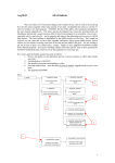
Program steps:
These are summarised in figure 5.8.
Figure 5.8
EHJLQ
!
VHOHFW LQSXW
SDUDPHWHU ILOH
IRU LPSXULW\
!
LQSXW LVRWRSH
PDVVHV IRU
LPSXULW\ DQG K\G
!
VHOHFW ILOWHU
FKDUDFWHULVWLFV
URJHQ &; GRQRU
HQG
MRE SDUDPHWHUV
DQG LQLWLDWH
WDEOH
VHW EDFNJURXQG
!
RXWSXW VXPPDU\
RXWSXW PDVWHU
ILOHV
IRUPDW $')
DVVLJQ
WHPSHUDWXUH
DQG GHQVLW\
UDQJHV
Interactive parameter comments:
The program uses parametric forms for zero density recombination, ionisation and
radiated power loss coefficients, type adf03, to prepare standard (unresolved, stage to
stage) iso-nuclear master files for a particular element of type adf11. The iso-nuclear
master files may be prepared over arbitrary ranges of electron temperature and
electron density.
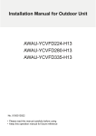
The file selection window is shown below:
ADAS User manual
Chap5-08
17 March 2003
1
2
3
4
1.
2.
ADAS User manual
Data root shows the full pathway to the appropriate data sub-directories.
Click the Central Data button to insert the default central ADAS pathway to
the correct data type. The appropriate ADAS data format for input to this
program is adf03 (‘atompars files’). Click the User Data button to insert the
pathway to your own data. Note that your data must be held in a similar file
structure to central ADAS, but with your identifier replacing the first adas,
to use this facility. The Data root can be edited directly. Click the Edit Path
Name button first to permit editing.
Available sub-directories are shown in the large file display window. Click
on a name to select it. The selected name appears in the smaller selection
window above the file display window. Then its sub-directories in turn are
Chap5-08
17 March 2003
displayed in the file display window. Ultimately the individual data-files are
presented for selection. Data-files all have the termination .dat.
A second file may be selected which specifies a spectral filtration to be
applied to the radiated power. Filter files are archived in format adf35 and
can be prepared and interrogated using the codes ADAS414 and ADAS415
respectively.
Once the data file is selected, the set of buttons at the bottom of the main
window become active. Clicking on the Browse Comments button displays
any information stored with the selected data-set. Clicking the Done button
moves you forward to the next window. Clicking the Cancel button takes
you back to the previous window
3.
4.
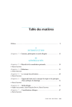
The processing options window has the appearance shown below
1
2
5
4
3
1.
2.
3.
4.
ADAS User manual
At the top of the window, an arbitrary title may be given for the case being
processed.
The name of the data file under analysis and any filter file being used are
shown. The button Browse Comments allows display of the information
field section at the foot of the named atompars file, if it exists.
The lower sub-windows allow the plasma electron temperature and electron
density for production of the output adf11 standard master files to be
specified. Select on the required temperature units. This choice determines
to the units used in the adjacent temperature range selection window.
Specify lower temperature limit, upper temperature limit and number of
temperatures in the editable boxes. ADAS408 then creates the temperature
grid equally spaced in the logarithm. Note that the output files in fact
contain the temperatures in eV (see the ADAS User Manual, appxb-11).
Similarly specify the electron density limits and number of grid points.
Enter the mass number for the actual isotope of the element required. For
information the element chemical symbol is displayed. Also, the mass
number of hydrogen isotope constituting the primary plasma species is
required.
Chap5-08
17 March 2003
5.
The Exit to Menu icon is present in ADAS408. Clicking the Done button
causes the output options window to be displayed. Remember that Cancel
takes you back to the previous window.
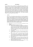
The output options window is of restricted form. It only offers the option of an
output files. There is no output graph.
1
2
3
4
5
6
1.
2.
3.
ADAS User manual
The adf11 iso-nuclear master file output comprises several. The template
shows the file naming structure
Collections of adf11 files are held by year number and element. Enter a two
digit year number for the output. Note that any two digits are acceptable
and ‘fictitious’ years can be used for special collections if so desired. The
element name is inserted automatically from the atompars input file.
The filter name field of the template is only sensitised if a filter file has been
selected on input. The convention in the past was that in the simple cut-off
case, the filter name had the prefix ‘ev’ followed by the numerical value of
the cut-off energy in eV. In the true filter case (which was restricted to
beryllium/silicon, the filter name had the prefix ‘ft’ followed by the first two
Chap5-08
17 March 2003
4.
5.
6.
significant figures of the beryllium and silicon thicknesses. The much
greater flexibility of the full Henke filter implementation is not
encompassed by the old convention. Filter names are at your own choice
although central ADAS will continue to have adf11 data following the old
naming. Note also that the output files can be placed in a directory of your
choice rather than entering the pass directory.
Click on the buttons for the output adf11 file classes you wish. The filtered
power classes are only sensitized if a filter file has been selected.
The standard line printer text output file summarising the options selected
for ADAS408 is available. The Replace and Default File Name buttons are
present for the text output file as usual.
The Exit to Menu icon is present in ADAS408. Clicking the Done button
causes the output options window to be displayed. Remember that Cancel
takes you back to the previous window.
Illustration:
There is no graphical display from this code.
Table 5.8a
*****************
RUN SUMMARY FOR PROGRAM GENERATING STANDARD
*******************
****************
ISONUCLEAR MASTER FILES FROM PARAMETRIC FORMS *******************
***************************** ADAS408 - DATE: 19.08.03 ******************************
INPUT PARAMETER FILE
: /home/adas/adas/adf03/atompars/atompars_mm#ar.dat
Output files:
/home/mog/pass/acd89_ar.pass
/home/mog/pass/scd89_ar.pass
/home/mog/pass/ccd89_ar.pass
/home/mog/pass/prb89_ar.fil_jet.pass
/home/mog/pass/plt89_ar.fil_jet.pass
/home/mog/pass/pls89_ar.pass
/home/mog/pass/prc89_ar.fil_jet.pass
/home/mog/pass/prb89_ar.pass
/home/mog/pass/plt89_ar.pass
/home/mog/pass/prc89_ar.pass
-------------------
IMPURITY INFORMATION:
--------------------ELEMENT SYMBOL
NUCLEAR CHARGE
LOWEST ION CHARGE
HIGHEST ION CHARGE
ATOMIC MASS NUMBER
-------------------
=
=
=
=
=
NEUTRAL DONOR INFORMATION:
-------------------------ELEMENT SYMBOL
=
NUCLEAR CHARGE
=
ATOMIC MASS NUMBER
=
ar
18
0
17
40.00
H
1
2.01
FILTER INFORMATION:
-------------------
ADAS User manual
Chap5-08
17 March 2003
Filter from : /home/adas/adas/adf35/jet_filter.dat
ELECTRON TEMPERATURE/DENSITY INFORMATION:
-----------------------------------------
NUMBER OF VALUES
MINIMUM VALUE
MAXIMUM VALUE
TEMPERATURE (EV)
---------------=
48
=
1.0000D+00
=
5.0000D+04
DENSITY (CM-3)
-------------26
1.0000D+10
1.0000D+15
(NOTE: EQUAL INTERVALS IN THE LOGARITHM ARE SET)
Notes:
ADAS User manual
Chap5-08
17 March 2003