1
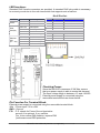
LED functions:
Standard RJ45 female connectors are provided. A standard RJ45 plug cable is necessary
to connect your device to the unit since switch that supports auto crossover.
RJ-45 Pin-Out:
LED
Power
Fiber
Port(P0)
Ethernet
Port
(P1 ~ P4)
Color
Description
Pin#
Signal Name
Function
Red On
Power is On
1
TD+
Transmit Data
Red Off
Power is Off
2
TD-
Transmit Data
Yellow On
Full Duplex
3
RD+
Receive Data
Yellow Off
Half Duplex
4
NC
No Connection
Green On
Link/Act
5
NC
No Connection
Green Off
Not Networking
6
RD-
Receive Data
Yellow On
Link/Act
7
NC
No Connection
Yellow Off
Not Networking
8
NC
No Connection
Green On
Link to 100 Mbps
Green Off
Link to 10 Mbps
Checking Power:
Since the NS-205Fx consumes 3.3W Max, ensure
that your power supply is able to meets this demand.
The Input voltage range is between +10 and +30VDC.
External power supply is connected using the
removable terminal block as shown below:
Pin Function For Terminal Block:
External power supply is connected using the removable terminal block:
+Vs : Power input +10 to +30V
GND : Ground
F.G. :F.G. stands for Frame Ground (protective
ground). It is optional. If you use this
pin, it can reduce EMI radiation; improve EMI
performance and ESD protection.
NS-205Fx User’s Manual (Version 1.0, Aug/2006) --------------- 2