1
Confidential
............................................................................................................................................................................................ 78
User Manual
for
1G Ethernet BGP Simulator
All Rights Reserved. Copying of this document or parts of it is prohibited.
1
Confidential
............................................................................................................................................................................................ 78
Content
Table of Contents
Product Manual....................................................................................................................................................................... 5
Execution..................................................................................................................................................................................8
Login................................................................................................................................................................................. 8
1 System Info...........................................................................................................................................................................9
2 Settings............................................................................................................................................................................... 10
2.1 LAN Settings........................................................................................................................................................10
2.1.1 Management Port Settings....................................................................................................................... 11
2.1.2 Router Port.................................................................................................................................................. 12
2.2 LAN Status..............................................................................................................................................................13
2.3 BGP Settings.......................................................................................................................................................... 14
2.3.1 Add router configuration............................................................................................................................15
2.3.1.1 Router ID..........................................................................................................................................17
2.3.1.2 Neighbors........................................................................................................................................ 18
2.3.1.3 Networks.......................................................................................................................................... 20
2.3.1.4 Weight.............................................................................................................................................. 21
2.3.2 Delete Configuration.................................................................................................................................. 23
2.3.3 List of neighbors......................................................................................................................................... 25
2.3.3.1 Edit Neighbor.................................................................................................................................. 27
2.3.3.2 Delete Neighbor..............................................................................................................................29
2.3.4 Routes..........................................................................................................................................................29
2.4 System Upgrade.................................................................................................................................................... 32
3 Profiles.................................................................................................................................................................................38
3.1 View Profile............................................................................................................................................................. 38
3.1.1 Add new Profile.......................................................................................................................................... 39
3.1.2 Edit Profile................................................................................................................................................... 41
3.1.3 Delete Profile.............................................................................................................................................. 43
3.2 Apply Profile............................................................................................................................................................46
3.2.1 Start Profile................................................................................................................................................. 46
3.2.2 Edit Applied Profile.....................................................................................................................................49
3.2.3 Stop Profile (Simulation)........................................................................................................................... 52
3.2.4 Toggle Profile............................................................................................................................................... 55
4 Statistics..............................................................................................................................................................................61
5 Show Routing Tables........................................................................................................................................................63
5.1 Kernel Routing Table.............................................................................................................................................63
5.2 BGP Routing Table................................................................................................................................................64
6 Graphical Visualization..................................................................................................................................................... 70
7 Help......................................................................................................................................................................................72
8 Administration......................................................................................................................................................................73
8.1 Users......................................................................................................................................................................... 74
8.2 Roles......................................................................................................................................................................... 79
8.3 Permissions...............................................................................................................................................................82
9 Logout:.................................................................................................................................................................................85
10 Shutdown.......................................................................................................................................................................... 86
11 Copyright and Licenses.................................................................................................................................................. 88
List of Figures
Figure
2 -2 LAN Status.................................................................................................................................17
Figure
3 -6 Bit Errors (Packet corruption) Check..........................................................................................77
Figure
5 -1.BGP Multi-path Testing Topology..............................................................................................86
All Rights Reserved. Copying of this document or parts of it is prohibited.
2
Confidential
............................................................................................................................................................................................ 78
How To(s)
How to Check which Ethernet interface is connected before assigning IP? ...............................................15
How to Test Bandwidth parameters?..............................................................................................................73
How to Test BGP Dynamic Decisions?...........................................................................................................86
List of Tables
Table
0 -1. Main Menu..................................................................................................................................9
Table
1 -1. System Info...............................................................................................................................11
Table
2 -0. Settings Menu...........................................................................................................................13
Table
2 -1. LAN Settings Menu...................................................................................................................15
Table
2 -2. LAN Status................................................................................................................................17
Table
2 -3. BGP Settings Menu..................................................................................................................20
Table
2 -4. Adding BGP Configuration........................................................................................................23
Table
2 -5. Deleting BGP Configuration......................................................................................................47
Table
2 -6. List of BGP Neighbors..............................................................................................................49
Table
2 -7 Neighbor Info.............................................................................................................................52
Table
2 -8. Return to Main Menu................................................................................................................55
Table
3 -0. Profiles Menu............................................................................................................................58
Table
3 -1 Add Profile.................................................................................................................................66
Table
3 -2. Edit Profile................................................................................................................................69
Table
3 -3. Delete Profile............................................................................................................................70
Table
3 -4. Apply Profile..............................................................................................................................72
Table
3 -5. Stop Profile Simulation..............................................................................................................73
Table
4 -0. Statistics....................................................................................................................................79
Table
5 -0 Routing Tables...........................................................................................................................81
Table
5 -1 Kernel Routing Table..................................................................................................................83
Table
5 -2 BGP Routing Table....................................................................................................................86
Table
6 -0 Log-out.......................................................................................................................................94
List of Abbreviations
Abbreviation
Definition
EDS
Ethernet Delay Simulator
BGP
Border Gateway Protocol
All Rights Reserved. Copying of this document or parts of it is prohibited.
3
Confidential
............................................................................................................................................................................................ 78
ASN
Autonomous System Number
All Rights Reserved. Copying of this document or parts of it is prohibited.
4
Confidential
............................................................................................................................................................................................ 78
Product Manual
Features
The EBS v2.1.xx Software features are broadly categorize into three Sub-system:
1. Traffic Simulation sub-system
2. Border Gateway Protocol (BGP) sub-system
3. LAN
1. Traffic Simulation sub-system
Handle Traffic Bandwidth Control and Shaping
Each IP Address maintains its own profile of Bandwidth Shaping
Simulation of Real-time Delay,Jitter,Packet Corruption, Duplication,Reordering,Loss on constant
basis or depending on Correlation.
2.Border Gateway Protocol (BGP) sub-system
Perform Routing Decision Dynamically based on number of networks available at that instant.
Adding Neighbors, Networks to System.
Forwarding of packets based on routes created dynamically.
View Routes Advertised to/by Neighbors.
Assign Preference(Weight) to a particular path from list of available Multiple paths
3.LAN
Able to Detect and Configure Scalable number of network interfaces.
Show Status of connected/available Network Ports.
Show
whether Traffic Shaping Profile is active for a particular interface at that instant.
System Requirements
Operating System : Ubuntu 12.04 or higher
Command-line Terminal :
gnome-terminal
Web Browser: Mozilla Firefox 37+ ,Google Chrome 40+
Apache Tomcat Server : version 7.0.xx
Java : version 1.6 update 38
Linux Kernel version : 3.8.0-29-generic
Hardware Requirement : EDS-1G
RAM size : 512MB(Minimum)
Number of Network Cards supported : Scalable
All Rights Reserved. Copying of this document or parts of it is prohibited.
5
Confidential
............................................................................................................................................................................................ 78
Prerequisites
1. Ensure that gnome-terminal is installed into your system. If not installed ,you have to run the setup
manually from command-line.
2. Ensure that your web browser is updated with the latest version .
3. Ensure the Ipv4 Forwarding is enabled.Or try this command by logging as root user to Set this
feature
$ echo 1 > /proc/sys/net/ipv4/ip_forward
Installation
Take the “EBS-2.1.xx.tar.bz2” archive file and copy it onto your home folder. Extract it by Clicking Right
button of Mouse..A Sub-menu will be opened ,in that menu search option “Extract here” and click it to extract
archive content on home folder.Go to the extracted folder “EBS-2.1.xx”
Ensure that you have gnome-terminal installed on your system .Go to the extracted folder and Double Click
the RunSetup_64bit application.A terminal window will get open and it will ask your choice. Select option “1”
for installation.It will ask sudo password to Elevate Privileges.Entering the correct sudo password will install
application into system.If setup is not installed change user “rwx”(Read,Write,Execute) permissions of all
the files in the folder to be “777” from command line as shown below.
1.Install
2.Uninstall
3.Debug
Enter your choice:
1
[sudo] password for user:
You may also run the setup.sh script from command line
as
$ tar -xvf EBS-2.1.xx.tar.bz2
$ cd EBS-2.1.00
$ sudo chmod 777 *
[Please Provide sudo user password]
$ sudo ./setup.sh install
The setup requires to execute Commands with Elevated Privileges therefore while the setup script is running
it will ask for sudo password. After entering the password setup will compile the Application and add
necessary files to '/home/$USER/EDS2'
folder
While installation setup will install necessary libraries by downloading them from Internet.So please ensure
the Target system is connected to internet.
There is a short-cut 'eds_bgp' provided from Desktop .Along with that the application 'eds_bgp'
available as separate command from command line.
is also
Note:If you are facing some problem during installation use the setup.sh script with -x flag to diagnose the
issue . On directory containing EBS setup files run from common line as.
$ sudo /bin/bash -x ./setup.sh install
All Rights Reserved. Copying of this document or parts of it is prohibited.
6
Confidential
............................................................................................................................................................................................ 78
Un-installation
Locate the extracted folder and Double Click the RunSetup_64bit application.A terminal window will get
open and it will ask your choice. Select option “2” for un-installation.
1.Install
2.Uninstall
3.Debug
Enter your choice:
2
Use sudo user privilege and uninstall the Application via setup.sh script from command line as
$ ./setup.sh uninstall
All Rights Reserved. Copying of this document or parts of it is prohibited.
7
Confidential
............................................................................................................................................................................................ 78
Execution
Login
Open browser present on the system(Mozilla Firefox 37+ or Chrome 40+ would be better) and type the ip
address of the server and port number followed by /ebs (http://X.X.X.X:8080/ebs) . Page will be opened
and asking for username and password to login to GUI based application Currently the administrator user
name is “eds@10g” . The default password is set as “madmax13” . Once we login to EBS system ,
main page will show following contents:
1. System Info
2. Settings
3. Profiles
4. Statistics
5. Routing Tables
6. Graph
7. Help
8. Administration
9. Logout
10. Shutdown
Table 0-1. Main Menu
We Can also access the system Remotely from other systems by applying url in following format.
http://192.168.0.251:8080/ebs/
The IP Specified is the IP Address of Management Port.It will ask for EDS password. EDS password is by
default set as “madmax13”. Entering this password will show the Main Menu of EBS application..
All Rights Reserved. Copying of this document or parts of it is prohibited.
8
Confidential
............................................................................................................................................................................................ 78
1 System Info
From the Home Screen System Specific Information will be displayed ,for example. Kernel Version, Software
version.System uptime,Build information.
Table 1-1. System Info
All Rights Reserved. Copying of this document or parts of it is prohibited.
9
Confidential
............................................................................................................................................................................................ 78
2 Settings
Set your mouse pointer
to
Settings Menu.This option configures the IP Addresses of entire EBS
system.Basically there are three types of settings available underneath
1.LAN configuration
2.Border Gateway Protocol (BGP) configuration.
3.Upgrade
Table 2-0. Settings Menu
2.1 LAN
Settings
Under Settings Menu , press button “LAN” to switch to LAN settings menu. At LAN settings we will inquire
about the name of interface whose IP Address we want to choose.LAN Settings is sub-divided into two
sections:
Management Port Settings
Router Port Settings
All Rights Reserved. Copying of this document or parts of it is prohibited.
10
Confidential
............................................................................................................................................................................................ 78
2.1.1 Management Port Settings
This settings are meant to provide Network configurations that ensures internet access to Supermicro
System and provide mechanism to upgrade and diagnose the System by Programmer.
Normally a private class IP network is used so that Supermicro system is accessible remotely from intranet.
If a local DNS server is managing that Private network , then Supermicro System can access internet via
local DNS server.
Management Setting comprises of three main options:
Add
Delete
Edit
Add and Edit will open same kind of Pop-up Menu, difference is Add will have list of available Management
Interface as the first text Field while Edit will fetch the existing values of Interface details keeping the
Interface field as un-editable(Freeze).There are two Management Ports available .URL to access the
Configurations of EDS System has IP address from among one of the two Management Ports IP addresses.
Delete Option will Delete a particular interface Details and set of default values will get assigned .
Management port setting requires following details :
Interface Name
IP Address
Subnet Mask
Gateway IP
DNS IP
DNS Name
Hostname
Note :Configuring the Management Port requires sufficient knowledge of the Required fields of Management
Port Details.Improper settings may hinder your Internet connection of EDS System . Be sure and specific to
what are you going to do with Management Port.
A separate documentation is provided on how to configure Management Port in the “doc “ folder of source
file.
All Rights Reserved. Copying of this document or parts of it is prohibited.
11
Confidential
............................................................................................................................................................................................ 78
Management Port Settings
2.1.2 Router Port
Router Ports are meant to establish connection between two different Networks. There can be a scalable
number of Router ports , depending of number of Network cards inserted before starting the EDS System.
Just like Management ports, it also supports three types of operations:
Add
Delete
Edit
As the number of Router Ports is dynamic and it changes from the need of user, so the list of Router Ports
may .also increase or decrease with use.
Router Port Setting requires following details:
Port name
IP Address
Subnet Mask
Clicking on Add Option will show a pop-up menu with names of ports in drop-down menu.
Editing will freeze the Port Name field, keeping IP address and Subnet mask Editable.
Clicking on Delete Option will write default settings on the Port.
All Rights Reserved. Copying of this document or parts of it is prohibited.
12
Confidential
............................................................................................................................................................................................ 78
Router Port Settings
How to Check which Ethernet interface is connected before assigning IP?
To get the name of Ethernet interface ,plug the first end of LAN cable to some existing system Take
second end of the connected cable and insert into one of the interfaces. Select Option “2” from Settings
Menu (2.2 LAN Status) to check which Ethernet port link goes to LINK UP state. Then Return back to
Settings menu.
Again go to to LAN Settings Sub-menu [2.1]to set the IP Address of just observed Ethernet Port.
2.2 LAN Status
From Settings Menu switch to view LAN status by selecting
option “Status ”
The current state of all the available interfaces will be displayed with following information:
1.IP Address
2.MAC Address
3.Link Status
4.Link Speed Supported
5.Currently Active Traffic Shaping Profile
All Rights Reserved. Copying of this document or parts of it is prohibited.
13
Confidential
............................................................................................................................................................................................ 78
Table 2-2. LAN Status
This LAN Status Table will give the real-time status of all available ports including Management Ports too.
The Management ports will be suffixed with (MGMT) to make them distinct from other ports of Router. If any
Traffic Shaping Profile is active for the router ports ,then the Traffic Shaping Field will show “Applied” .While
It is always shows “ Not Applied “ for Management Port
Note : The Speed Field will show “Unknown!” in case the network port is left Open.Traffic Shaping should be
configured keeping the Link speed of ports in mind.
2.3 BGP Settings
BGP Settings will take care of all the BGP specific customization include
1.Add/enable router configuration
2.Delete Configuration
3.List of neighbors
4.Neighbors Info
5.Previous menu
All Rights Reserved. Copying of this document or parts of it is prohibited.
14
Confidential
............................................................................................................................................................................................ 78
Table 2-3. BGP Settings Menu
2.3.1 Add router configuration
When we are configuring router for the first time then this option will ask for new Autonomous System
Number ASN and once It is set then it will check with the existing router configuration.Add option will be
active only when there is no AS number configured for the Router.Other wise Delete Option will replace Add
option in BGP menu.
If we have deleted the router configuration then it may ask again for New ASN.
For a ASN following
Parameters can be added and shown in the Submenu:
1.Router ID
2.Neighbors
3.Networks
4.Weight
All Rights Reserved. Copying of this document or parts of it is prohibited.
15
Confidential
............................................................................................................................................................................................ 78
Add Router configuration
All Rights Reserved. Copying of this document or parts of it is prohibited.
16
Confidential
............................................................................................................................................................................................ 78
BGP Main Menu
2.3.1.1 Router ID
Go to following Submenu “ Main Menu->Settings ->BGP -> Add Router Configuration “ and enter IP address
in text Field labeled Router ID to set router id.
If all things go well, then a new router ID will be shown in a pop-up message.
All Rights Reserved. Copying of this document or parts of it is prohibited.
17
Confidential
............................................................................................................................................................................................ 78
Table 2-4. Adding BGP Configuration
2.3.1.2 Neighbors
Go to following menu path “ Main Menu->Settings ->BGP -> Add Router Configuration “ and enter
Neighbor Details as IP Address and Remote AS number to Add neighbors.
Once Add ,they can be seen in “Settings -> BGP ->Neighbors “ .Press Button “Neighbors” on the top right
corner of screen
to view “List of neighbors ” on your system
Set the same configurations on the Neighbor systems.But set neighbor as EDS-10G system ip address and
Autonomous Number instead.
All Rights Reserved. Copying of this document or parts of it is prohibited.
18
Confidential
............................................................................................................................................................................................ 78
Once we set Neighbors at both the ends , then we can see State Prefix
Received in both ends to be a Number instead of a Text. That shows Connection is established and BGP
message exchange is happening.
Add Neighbour
All Rights Reserved. Copying of this document or parts of it is prohibited.
19
Confidential
............................................................................................................................................................................................ 78
2.3.1.3 Networks
Using this option we will add/remove network in our bgp router configuration.If the neighbors are connected
via a certain network,then we can specify network in their BGP configuration,so as the BGP will always
choose internal path to establish connection through the particular network.Networks with internal path will
set themselves as the gateway for the next HOP of network.
If the internal network is not added , then the immediate neighbor will regarded as the Default Gateway to
reach the network.
After entering Network IP and Subnet-mask and pressing Save button will open up a pop-up screen showing
network along with subnet mask which is added recently.
All Rights Reserved. Copying of this document or parts of it is prohibited.
20
Confidential
............................................................................................................................................................................................ 78
Add Network
2.3.1.4 Weight
Setting the weight will override the default routing decision of BGP and a certain neighbour with highest
weight is given higher preference then the rest. After setting the weight ,the bgp daemon will be restarted
automatically to reflect the change
To check the updated Weight ,we need to go back to Routes Menu and check received Routes from the
particular Neighbor to verify whether weight is updated for BGP daemon
All Rights Reserved. Copying of this document or parts of it is prohibited.
21
Confidential
............................................................................................................................................................................................ 78
All Rights Reserved. Copying of this document or parts of it is prohibited.
22
Confidential
............................................................................................................................................................................................ 78
Add Weight
2.3.2 Delete Configuration
From BGP Configuration Menu select option “Delete” to delete an existing Autonomous System Number
based configuration.
A warning Message will be displayed prompting for user confirmation. Remember after the deletion all the
Path, Neighbors and Network will be removed from the existing Configuration.
Once deleted they can't be recovered in later point of time .Stay cautious to use this options. As the kernel
routing decision will be based on this option.
After Deletion , the Add button will replace Delete button so user can enter his new configurations..
All Rights Reserved. Copying of this document or parts of it is prohibited.
23
Confidential
............................................................................................................................................................................................ 78
All Rights Reserved. Copying of this document or parts of it is prohibited.
24
Confidential
............................................................................................................................................................................................ 78
Table 2-5. Deleting BGP Configuration
2.3.3 List of neighbors
Using this option will list the available neighbors connected to our Autonomous System AS. State of
Neighbors is a very important attribute for trouble shooting connections.
The Neighbors who are connected but not advertised their routes are shown state as “Active”
While the Neighbors who are advertising their routes show their State with some number.
The State is displayed as the last column on List of neighbors Table.
Adjacent Delete/Edit Buttons are provided next to every neighbor so that a user can modify Neighbor without
entering much details.
Under this following two operations can be performed:
1)
Edit Neighbor
2)
Delete Neighbor
All Rights Reserved. Copying of this document or parts of it is prohibited.
25
Confidential
............................................................................................................................................................................................ 78
Table 2-6. List of BGP Neighbors
BGP States Diagram
BGP neighbor states
When BGP is configured with a neighbor IP address, it goes through a series of stages before it reaches the
desired Established state in which BGP has negotiated all the required parameters and is willing to exchange
BGP routes.
1.
IDLE State :
All Rights Reserved. Copying of this document or parts of it is prohibited.
26
Confidential
............................................................................................................................................................................................ 78
Verifying route to neighbor.BGP refuses all incoming connections. No
BGP resources are allocated in Idle state, and no incoming BGP connections are allowed.
2.Connect State :
BGP waits for a TCP connection to be completed. If successful, the BGP state machine moves into
OpenSent state after sending the OPEN message to the peer. Failure in this state could result in either going
into Active state or Connect state, or reverting back to Idle state, depending on the failure reasons.
3. Active State :
Attempting connectivity to neighbor. In this state, a TCP connection is initiated to establish a BGP
peer relationship. If successful, BGP sends its OPEN message to the peer and moves to OpenSent state.
Failure can result in going to the Active or Idle states.
4. OpentSent State :
Open message sent to neighbor. After sending an OPEN message to the peer, BGP waits in this
state for the OPEN reply. If a successful reply comes in, the BGP state moves to OpenConfirm and a keepalive is sent to the peer. Failure can result in sending the BGP state back to Idle or Active.
5. OpenConfirm State :
Neighbor replied with open message. The BGP state machine is one step away from reaching its
final state (Established). BGP waits in this state for keep-alives from the peer. If successful, the state moves
to Established; otherwise, the state moves back to Idle based on the errors.
6. Established State :
connection between neighbors established. This is the state in which BGP can exchange information
between the peers. The information can be updates, keep-alives, or notification.Established State will be
indicated by an integer value.
2.3.3.1 Edit Neighbor
Adjacent “Edit” Buttons to Neighbors will be used to edit AS number of already added Neighbor.
All Rights Reserved. Copying of this document or parts of it is prohibited.
27
Confidential
............................................................................................................................................................................................ 78
Edit Neighbor.
All Rights Reserved. Copying of this document or parts of it is prohibited.
28
Confidential
............................................................................................................................................................................................ 78
2.3.3.2 Delete Neighbor
Adjacent Delete Button will remove the neighbor.
Delete Neighbor
2.3.4 Routes
This options can provide a valuable insight into BGP neighbors .This option will show the list of routes shared
between EDS-System and its neighbors.
To get the list of routes sent to neighbor use option “Sent”
To get the list of routes sent by neighbor use option “Received”
To Delete the network from BGP system , adjacent Delete Buttons are provided in the Sent Routes option.
We can’t delete any received Routes ,hence Received Routes menu has no such buttons
All Rights Reserved. Copying of this document or parts of it is prohibited.
29
Confidential
............................................................................................................................................................................................ 78
Table 2-7 Routes
Sent Routes
All Rights Reserved. Copying of this document or parts of it is prohibited.
30
Confidential
............................................................................................................................................................................................ 78
BGP Sent Routes
Recieved Routes
All Rights Reserved. Copying of this document or parts of it is prohibited.
31
Confidential
............................................................................................................................................................................................ 78
BGP Received Routes
How to Test BGP Dynamic Decisions?
Test setup for BGP Dynamic Decision is provided at the end of section [5.3] .
2.4
System Upgrade
System Upgrade requires following set of steps to be performed:
1)
To upgrade software, download the upgrade file package named EDS_PACKAGE.tar
2)
From the Settings Menu select option Upgrade to switch to Upgrade Menu.
3)
Upgrade Menu will have Browse Button , which will be used to locate the downloaded upgrade file.
4)
After Selecting the upgrade file, click Apply Button on Upgrade menu to apply the changes.
5)
It will prompt for upgrade Password. , enter “madmax13” and press Update.
6)
If the password and File is found valid , then a message will be displayed as “Success”.So far only
Binary files and scripts have been transferred .But server is still running with old configuration.
7)
To upgrade Server , we need to stop a server first and run a script in Linux command prompt.
8)
Go to the EDS-BGP home folder by typing following command in LInux terminal as.{ cd ~/EDS2 }
9)
Run the following script with root user privileges as { sudo ./update_gui.sh }.
10) While installing the new configurations , script can ask for Server IP Address. It is best to give one
among the IP Address of the Management Port IP Addresses .
11) Once , the script has completed its work ,restart the
EDS-10g
server.
All Rights Reserved. Copying of this document or parts of it is prohibited.
32
Confidential
............................................................................................................................................................................................ 78
All Rights Reserved. Copying of this document or parts of it is prohibited.
33
Confidential
............................................................................................................................................................................................ 78
All Rights Reserved. Copying of this document or parts of it is prohibited.
34
Confidential
............................................................................................................................................................................................ 78
All Rights Reserved. Copying of this document or parts of it is prohibited.
35
Confidential
............................................................................................................................................................................................ 78
All Rights Reserved. Copying of this document or parts of it is prohibited.
36
Confidential
............................................................................................................................................................................................ 78
System Upgrade
All Rights Reserved. Copying of this document or parts of it is prohibited.
37
Confidential
............................................................................................................................................................................................ 78
3 Profiles
We use profiles names for storing Bandwidth Limit and other traffic parameters .Each profile can be applied
to Multiple Source and Destination IP Addresses pairs. Apart from Bandwidth various other types of
simulations can be possible as : Delay ,Packet loss ,Bit-wise Error ,Duplication,Re-ordering.
After setting the Profile parameters from “View Profiles” Menu ,we need to apply them to Source and
Destination IP Address from “Apply Profile” Submenu.
Profiles has following sub-menus:
1.
2.
View Profile
Apply Profile
Table 3-0. Profiles Menu
3.1 View Profile
Use this option to Add/Edit/Delete a new profile in EBS system.Adding the
Name and Traffic Shaping Parameters just like:
1.Interface Name
2.Bandwidth
3.delay
4.loss
5.reorder
6.duplication
7.Bit Error(corrupt)
profile will ask the new profile
Each Profile thus created is applied to all the Router Interfaces.These Profiles first need to be created so as
to be applied in the later order of applying profile in “Apply Profile” submenu.
Please provide the parameters under the specified Range only else it will revert back to previous Menu
All Rights Reserved. Copying of this document or parts of it is prohibited.
38
Confidential
............................................................................................................................................................................................ 78
without setting up the parameters. Again enter the parameters in proper format
and range.
Also while specifying Reordering parameters please ensure you have specified delay parameters already
else the setting will fail to set parameters and revert to previous Menu
While specifying percentage it is not recommended to Enter percent Suffix(%) as it is understood as a default.
Note : Adding the parameters for a profile will directly not apply them to Traffic Shaping Sub-system .We
have to save them first so that they can be available when we want to apply the profiles to interfaces in
later point of our application execution. To apply a profile there is a separate section Apply Profile present
that will guide you on how to apply an existing profile to interface.
But if we Delete a profile while the profile is running then it will be stopped by application first before
deleting Profile.
View Profile supports three operations:
1) Add a new profile
2) Edit an existing Profile
3) Delete an existing Profile.
3.1.1 Add new Profile
Press Add Button in “View Profile” menu to add new Profile name and corresponding traffic shaping
parameters.
Pressing Add Button will open up a pop-up screen where we need to enter Profile details and save them via
“Save” Button.
Pressing the Save Button will show “Success” message on successful Addition of a profile.Along with that
new profile gets added in List of Profile with default Status and Multiple Fields.
When we apply the new profile from “Apply Profile” Tab , then it will show active status by displaying Green
icon along with Multiple field incremented to 1.
All Rights Reserved. Copying of this document or parts of it is prohibited.
39
Confidential
............................................................................................................................................................................................ 78
All Rights Reserved. Copying of this document or parts of it is prohibited.
40
Confidential
............................................................................................................................................................................................ 78
Table 3-1 Add Profile
3.1.2 Edit Profile
Use button “Edit” adjacent to each profile in “View Profiles” Menu to edit the Traffic shaping parameters of
currently existing profiles.Pressing the “Edit” button will open up a pop-up menu having list of parameters for
selected Profile.
After editing we need to save them. Application will automatically apply them on Traffic Shaping Subsystem to reflect the changes.To apply the edited profile we should press Button “Save” from Edit Profile
Pop-up screen .
The new changes can be visible from “Statistics” Menu.
All Rights Reserved. Copying of this document or parts of it is prohibited.
41
Confidential
............................................................................................................................................................................................ 78
Table 3-2. Edit Profile
All Rights Reserved. Copying of this document or parts of it is prohibited.
42
Confidential
............................................................................................................................................................................................ 78
3.1.3 Delete Profile
Delete Button is present in front of every profile.Pressing which , will delete the corresponding profile.
A warning message will get pop-up prompting for user confirmation, applying which will delete the Profile.
Pressing the “Delete” button will Stop simulation for all the Source-Destination IP pairs on which that profile
was applied.
This can be verified from the “Apply Profile” Tab or Statistics Menu.
All Rights Reserved. Copying of this document or parts of it is prohibited.
43
Confidential
............................................................................................................................................................................................ 78
Table 3-3. Delete Profile
All Rights Reserved. Copying of this document or parts of it is prohibited.
44
Confidential
............................................................................................................................................................................................ 78
Apply Profile Menu before and after Deleting a profile
Apply Profile Menu before and after Deleting a profile
All Rights Reserved. Copying of this document or parts of it is prohibited.
45
Confidential
............................................................................................................................................................................................ 78
3.2 Apply Profile
After adding/ editing the profile in View Profile Menu we use this option to Shape the Traffic from list of
existing profiles.
Pressing Apply Profile Tab will show a submenu having three fields:
1. List of Profile
2. Source IP Address
3. Destination IP Address
Along with these three fields, there are two optional user input fields which will take subnet mask as input for
Source IP & Destination IP Addresses respectively.
4.
5.
Source Subnet Mask
Destination Subnet Mask
These two fields will only get activated when we check the Subnet mask check-box , otherwise these fields
will remain inactive.Selection of Subnet Mask will apply the same profile over whole network range as
defined by subnet mask values. The subnet masks can be applied over CIDR networks.
Underneath these fields lies a Table that will show profile to IP Address pairs mapping .In short , applied
profile for pair of Source and Destination IP Addresses.
Following Actions can be performed to pair of Source and Destination IP Addresses
1. Start Profile
2. Change Profile
3. Stop Profile
4. Toggle Profile
3.2.1 Start Profile.
After entering Profile name ,Source and Destination IP Addresses ;and pressing “Apply Profile” button will
start a profile for Source and Destination IP Addresses.
This can be verified by “Statistics” Menu.
All Rights Reserved. Copying of this document or parts of it is prohibited.
46
Confidential
............................................................................................................................................................................................ 78
Table 3-4(a). Apply Profile for Single IP Address
All Rights Reserved. Copying of this document or parts of it is prohibited.
47
Confidential
............................................................................................................................................................................................ 78
Apply Profile over Subnet Mask
All Rights Reserved. Copying of this document or parts of it is prohibited.
48
Confidential
............................................................................................................................................................................................ 78
Table 3-4(b). Apply Profile for IP Addresses over Subnet Range
3.2.2
Edit Applied Profile
In Apply Profile Menu, from the table of Applied profiles rows ,we can reconfigure a profile for a SourceDestination IP pair onto which Profiles are already applied.
Pressing “Edit” Button will show a pop-up window where we can re-configure
Selected Source-Destination IP Pair.
some other Profile for
Leaving the Profile Name, all other fields will remain un-editable for user.
All Rights Reserved. Copying of this document or parts of it is prohibited.
49
Confidential
............................................................................................................................................................................................ 78
All Rights Reserved. Copying of this document or parts of it is prohibited.
50
Confidential
............................................................................................................................................................................................ 78
All Rights Reserved. Copying of this document or parts of it is prohibited.
51
Confidential
............................................................................................................................................................................................ 78
Table 3-5 .Edit Applied Profile
3.2.3 Stop Profile (Simulation)
Press Button “Delete” adjacent to Source-Destination IP pair from Apply Profile Menu to stop an existing
Simulation for the same pair.Deleting the IP pairs will decrement the Multiple count for the Profile Applied to
IP pair.If there are no other IP pairs sharing the same Profile , then Status of the Profile will revert back to
inactive state in View Profile Menu.
The Deleted IP pair will get removed from Statistics Menu also.
All Rights Reserved. Copying of this document or parts of it is prohibited.
52
Confidential
............................................................................................................................................................................................ 78
All Rights Reserved. Copying of this document or parts of it is prohibited.
53
Confidential
............................................................................................................................................................................................ 78
Table 3-5. Stop Profile Simulation
All Rights Reserved. Copying of this document or parts of it is prohibited.
54
Confidential
............................................................................................................................................................................................ 78
3.2.4 Toggle Profile
We can enable/disable an already applied profile as per our interest by Clicking the Toggle Profile Button .To
verify our action we can check Statistics menu before and after toggling the Profile.
All Rights Reserved. Copying of this document or parts of it is prohibited.
55
Confidential
............................................................................................................................................................................................ 78
Table 3-6. Toggle Profile
All Rights Reserved. Copying of this document or parts of it is prohibited.
56
Confidential
............................................................................................................................................................................................ 78
How to Test Bandwidth parameters?
1.
2.
3.
4.
5.
6.
Bandwidth
Delay
Loss
Reorder
Duplication
Bit Error(Corrupt)
1.Bandwidth
This parameter is mandatory to simulate traffic of any behaviour ,hence it can't be kept zero .Apply the
bandwidth parameters e.g (256kbps) using Profiles Menu. Run Iperf on some Server
(192.168.0.105)System in UDP mode as
$ iperf -s -u -i 1
On EBS system
run iperf client in udp mode thereby specifying Bandwidth as 1Mbps
$ iperf -c 192.168.0.105 -b 1mb
On Client side the bandwidth will show 1mbps but on Server system band width will get reduced to 256
kbps(approximately).
2.Delay
Apply some delay of 200ms on any active port in ping to the connected system.
If the reply time becomes equal to 200ms (or nearly)then Delay is happening.Due to ARP request the first
packet may have somewhat greater delay value.
ping 192.168.0.105
PING 192.168.0.105 (192.168.0.105) 56(84) bytes of data.
310 ms
64 bytes from 192.168.0.105: icmp_req=1 ttl=64 time=3
64 bytes from 192.168.0.105: icmp_req=2 ttl=64 time=2
200 ms
64 bytes from 192.168.0.105: icmp_req=4 ttl=64 time=2
200 ms
^C
--- 192.168.0.105 ping statistics --5 packets transmitted, 3 received, 40% packet loss, time 4010ms
rtt min/avg/max/mdev = 200.204/200.215/200.237/0.516 ms
2.1
Jitter
Values of jitter will limit the delay in range (Delay
±
Jitter )
3.Loss
Apply Loss Parameters without specifying Bit Errors (corrupt) parameters and ping from other systems to
Supermicro (EDS-10G) for a calculated no of attempts e.g. 40% loss of 10000 packets
All Rights Reserved. Copying of this document or parts of it is prohibited.
57
Confidential
............................................................................................................................................................................................ 78
$ sudo ping -i 0.0001 -c 10000 -q 192.168.0.1
PING 192.168.0.1 (192.168.0.1) 56(84) bytes of data.
--- 192.168.0.1 ping statistics --10000 packets transmitted, 6032 received, 39% packet loss, time 48107ms
rtt min/avg/max/mdev = 0.168/0.222/1.334/0.033 ms, ipg/ewma 4.811/0.228 ms
If the loss percentage observed becomes nearly equal to the loss percentage stored on Profile then Packet
Loss is being simulated by traffic shaping subsystem..
Loss percentage is clearly visible on ping statistics under Delay parameter.
4.Reorder
Reordering requires delay value to be non -zero so before setting reorder percentage set delay time first to
some known value e.g. 200ms and give some value of Reorder gap e.g. 5
Now ping to some connected system
$ ping 20.0.0.1
64 bytes from 20.0.0.1: icmp_req=3 ttl=64 time=193 ms
64 bytes from 20.0.0.1: icmp_req=4 ttl=64 time=193 ms
64 bytes from 20.0.0.1: icmp_req=5 ttl=64 time=193 ms
64 bytes from 20.0.0.1: icmp_req=6 ttl=64 time=0.089 ms
64 bytes from 20.0.0.1: icmp_req=7 ttl=64 time=193 ms
64 bytes from 20.0.0.1: icmp_req=8 ttl=64 time=193 ms
64 bytes from 20.0.0.1: icmp_req=9 ttl=64 time=193 ms
64 bytes from 20.0.0.1: icmp_req=10 ttl=64 time=193 ms
64 bytes from 20.0.0.1: icmp_req=11 ttl=64 time=0.099 ms
64 bytes from 20.0.0.1: icmp_req=12 ttl=64 time=193 ms
64 bytes from 20.0.0.1: icmp_req=13 ttl=64 time=193 ms
64 bytes from 20.0.0.1: icmp_req=14 ttl=64 time=193 ms
Leaving the highlighted ones ,other packets are reordered with a delay .
If after every 5 packets the response time is relatively lower then the other delayed values(such as 0.045ms)
that means some packets are being sent quicker then other remaining packets.
It implies Packet Reordering is happening
Packet reordering messages can easily be seen on iperf servers' output when it displays message “Out of
Order Packets Recieved”.
5 Duplication
Set the Duplication Parameters and apply them via Apply Profile[3.4} .Ping to a known system which can
be connected to any of EBS system.
$ ping 192.168.0.105
Watch the ping reply packets which has would look like
64 bytes from 20.0.0.1: icmp_req=1 ttl=64 time=187 ms
64 bytes from 20.0.0.1: icmp_req=1 ttl=64 time=187 ms (DUP!)
64 bytes from 20.0.0.1: icmp_req=2 ttl=64 time=187 ms
All Rights Reserved. Copying of this document or parts of it is prohibited.
58
Confidential
............................................................................................................................................................................................ 78
64 bytes from 20.0.0.1: icmp_req=2 ttl=64 time=187 ms (DUP!)
64 bytes from 20.0.0.1: icmp_req=3 ttl=64 time=187 ms
64 bytes from 20.0.0.1: icmp_req=3 ttl=64 time=187 ms (DUP!)
64 bytes from 20.0.0.1: icmp_req=4 ttl=64 time=187 ms
The word (DUP!)
specifies duplication is happening . Also we can check
values due to duplicated packets.
icmp_req
has identical
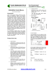
6.Bit errors ( corrupt) :
Set Loss Percentage value to 0 and set Bit Errors to some value. e.g. 50%.
As bit errors will be observed at the destination system so set this parameters into EDS10-G (supermicro)
System and from other remote system ping to EDS-10G ethernet port to which you have applied Traffic
Simulation scripts . The bitwise error packets will get dumped onto your Console.
ping 192.168.0.94 -c 10
PING 192.168.0.94 (192.168.0.94) 56(84) bytes of data.
64 bytes from 192.168.0.94: icmp_req=1 ttl=64 time=0.202 ms
64 bytes from 192.168.0.94: icmp_req=2 ttl=64 time=0.225 ms
wrong data byte #47 should be 0x2f but was 0x2e
#8
8 9 a b c d e f 10 11 12 13 14 15 16 17 18 19 1a 1b 1c 1d 1e 1f 20 21 22
23 24 25 26 27
#40
28 29 2a 2b 2c 2d 2e 2e 30 31 32 33 34 35 36 37
64 bytes from 192.168.0.94: icmp_req=4 ttl=64 time=0.232 ms
wrong data byte #41 should be 0x29 but was 0x39
#8
8 9 a b c d e f 10 11 12 13 14 15 16 17 18 19 1a 1b 1c 1d 1e 1f 20 21 22
23 24 25 26 27
#40
28 39 2a 2b 2c 2d 2e 2f 30 31 32 33 34 35 36 37
64 bytes from 192.168.0.94: icmp_req=5 ttl=64 time=0.206 ms
wrong data byte #15 should be 0xf but was 0xe
#8
8 9 a b c d e e 10 11 12 13 14 15 16 17 18 19 1a 1b 1c 1d 1e 1f 20 21 22
23 24 25 26 27
#40
28 29 2a 2b 2c 2d 2e 2f 30 31 32 33 34 35 36 37
64 bytes from 192.168.0.94: icmp_req=7 ttl=64 time=17.5 ms
64 bytes from 192.168.0.94: icmp_req=8 ttl=64 time=0.207 ms
64 bytes from 192.168.0.94: icmp_req=9 ttl=64 time=0.944 ms
--- 192.168.0.94 ping statistics --10 packets transmitted, 7 received, 30% packet loss, time 8998ms
All Rights Reserved. Copying of this document or parts of it is prohibited.
59
Confidential
............................................................................................................................................................................................ 78
Figure 3-6 Bit Errors (Packet corruption) Check
As it is clearly visible that 38% of packet loss is observed which can be taken as just near value to
Corruption errors percentage. To further verify you can check bit-wise errors into packets captured by
wireshark on Remote system.
All Rights Reserved. Copying of this document or parts of it is prohibited.
60
Confidential
............................................................................................................................................................................................ 78
4 Statistics
From the Main Menu set option “Statistics” to view network statistics. If we apply the profile to a pair of
Source and Destination IP Addresses from Profile Menu,then Statistics option will display the statistics of
Source-to-Destination IP Address corresponding to the Profile applied on All Ethernet Interfaces.Even if
same profile is applied to two pairs of Source-to-Destination IP Addresses , it will show Tx Bytes and
Packets separately for each such pair
As Traffic Shaping works best when applied for Egress Traffic , so here also only Transmission Bytes and
packets are shown.
All Rights Reserved. Copying of this document or parts of it is prohibited.
61
Confidential
............................................................................................................................................................................................ 78
Table 4-0. Statistics
All Rights Reserved. Copying of this document or parts of it is prohibited.
62
Confidential
............................................................................................................................................................................................ 78
5 Show Routing Tables
In the Main menu select option Routing Table to view the routing table.This option will display the BGP and
Kernel routing Table for every network. BGP routing table may have multiple paths to reach a network.But
the best selected path will be shown on Kernel Routing table.
1.Kernel Routing Table
2.BGP Routing Table
Table 5-0 Routing Tables
5.1 Kernel Routing Table
Select option “Kernel” to display Kernel Routing Table . It displays Kernel routing table with Gateways as
best selected neighbors by BGP protocol along with
that it will show Ethernet interface selected as per
neighbors network address .
All Rights Reserved. Copying of this document or parts of it is prohibited.
63
Confidential
............................................................................................................................................................................................ 78
Table 5-1 Kernel Routing Table
The Flags Field with value UG specifies the Gateway IP as Default Gateway to reach a network.
5.2 BGP Routing Table
Select option “BGP” to display BGP routing Table.It displays all possible paths to reach the network along
with corresponding Neighbors.Out of them the Best Selected Path and Neighbor will be marked by
{Default } Status .That special Neighbor's IP address will be selected as the default gateway by Kernel
Routing Table.
All Rights Reserved. Copying of this document or parts of it is prohibited.
64
Confidential
............................................................................................................................................................................................ 78
Table 5-2 BGP Routing Table
All Rights Reserved. Copying of this document or parts of it is prohibited.
65
Confidential
............................................................................................................................................................................................ 78
How to Test BGP Dynamic Decisions?
Figure 5-1.BGP Multi-path Testing Topology
We need five Systems to test dynamic routing decision of BGP
1. EDS 10G system:Dynamic routing decision will be made.
2. Router R: One of the node for Path R.
3. Router J: Another node for Path J.
4. Router S: Destination where EBS System wants to connect to.
5. PC: Source who uses EBS System to connect with Destination Router S.
Router R,J and S are any PCs with two set of network cards available . BGP Should be present in all the
three routers.For Testing Purposes we can install our software on Desktop Systems that will act as router
R,J and S with 2 network cards installed on each systems.
PC is an easy Linux system with only one Ethernet Card installed .It will be used only to check the network
connections and path followed.Make sure that software as traceroute or tracepath are installed on them.
PC will forward the request to EDS 10G(Supermicro).EDS-10G will take dynamic routing decisions to
connect to Router S through any one between two paths provided by Router R as Path R or by Router J
as Path J.
To understand the Dynamic Routing Procedure we will disconnect the link going through the default path
to break the traffic flow. After the link break EDS-10g will wait till 3 minute for the link to go UP .Failing
which it will declare that link as dead and select the alternate path for the traffic flow.If out of the failed
and alternate path.Traffic Shaping is applied then behavior of traffic shaping will be determined by the
nature of alternate path taken.
Note:To see dynamic Routing taking place, please be patient till 3 minutes for the BGP Routing Table to
update.You can check the updated entry in BGP Routing Table when the Next Hop Column will show
All Rights Reserved. Copying of this document or parts of it is prohibited.
66
Confidential
............................................................................................................................................................................................ 78
update for network 192.168.0.0.
In case the destination network is available directly from EDS System, then the setup will fail to contact
destination IP address due to ambiguity.
The following four Systems must have EBS-2.1.0 installed and running to set/get neighbors and
networks.Or Routers with BGP must have a mechanism to check neighbors and networks
Please Provide a unique Autonomous System Number to track each nodes of connection.
In our case the AS numbers are
1.
2.
3.
4.
EDS-10G----10
Router R-----7675
Router J------64512
Router S------65000
Check-list of Setup
1. Enable IPv4 forwarding in All the 4 systems or more .Use this command in root user mode to get/set.
$ cat /proc/sys/net/ipv4/ip_forward
$ echo 1 > /proc/sys/net/ipv4/ip_forward
2.
Separately check link state of each of the nodes in Supermicro System to fetch interface name using
LAN Status [2.2] option of EDS software.
3. Set the IP Address of each of the Ethernet ports thus found from Step 2 according to the Given
Topology in Figure 5-4.
Note: You can set ip address for Supermicro (EDS-10G )via EDS application.
For PC you can set ip address on linux terminal via command line as :
$ sudo ifconfig eth1 40.0.0.2 up
4. Ensure to ping the other end of connections successfully.
5. Router J and Router R should be connected via different network to Source.(EDS-10G).
6. Router J and Router R can be connected via different network to Destination.(Router S) also but in our
case we have connected the three into same LAN Network.
7. Add your respected neighbor AS number and its IP address onto your BGP routing Table.
8. Add the network of your neighbor IP onto BGP routing table.
For AS 10(EDS 10G)
Neighbor:20.0.0.2(AS 7675)
Neighbor:30.0.0.2(AS 64512)
Network : 20.0.0.0
Network : 30.0.0.0
Network : 40.0.0.0(For PC)
For AS 7675(Router R)
Neighbor:20.0.0.1(AS 10)
Neighbor:192.168.0.105(AS 65000)
Network : 20.0.0.0
Network : 192.168.0.0
For AS 64512(Router J)
Neighbor:30.0.0.1(AS 10)
Neighbor:192.168.0.105(AS 65000)
Network : 30.0.0.0
Network : 192.168.0.0
For AS 65000(Router S)
Neighbor:192.168.0.94(AS 64512)
Neighbor:192.168.0.112(AS 7675)
All Rights Reserved. Copying of this document or parts of it is prohibited.
67
Confidential
............................................................................................................................................................................................ 78
Network : 192.168.0.0
9. Ping to that LAN ip of Source which is active at that moment.
At AS 10(EDS 10G)
ping 20.0.0.2
At AS 7675(Router R)
ping 20.0.0.1
At AS 10(EDS 10G)
ping 30.0.0.2
At AS 64512(Router J)
ping 30.0.0.1
At AS 65000(Router S)
ping 192.168.0.112
ping 192.168.0.94
At AS 64512(Router J)
ping 192.168.0.105
At AS 7675(Router R)
ping 192.168.0.105
AT PC
ping 40.0.0.1
10. Now Ping to IP address of Destination
At AS 10(EDS 10G)
ping 192.168.0.105
At PC
Ping 192.168.0.105
11. Use Traceroute to inquire about the path followed.Note down the IP Addresss and AS number of
neighbor which is selected to reach the destination
At AS 10(EDS 10G)
traceroute 192.168.0.105
At PC
traceroute 192.168.0.105
13. Verify from Destination
At AS 65000(Router S)
ping 20.0.0.1
traceroute 20.0.0.1
ping 30.0.0.1
traceroute 30.0.0.1
ping 40.0.0.1
traceroute 40.0.0.1
ping 40.0.0.2
traceroute 40.0.0.2
14. Now disconnect the router who is best selected to reach destination. Wait for 3 minutes and check
whether the the destination is able to reply Ping requests from EDS-10g System as source and vice-versa
At AS 10(EDS 10G)
traceroute 192.168.0.105
At AS 65000(Router S)
ping 20.0.0.1
traceroute 20.0.0.1
OR
ping 30.0.0.1
traceroute 30.0.0.1
AND
All Rights Reserved. Copying of this document or parts of it is prohibited.
68
Confidential
............................................................................................................................................................................................ 78
ping 40.0.0.1
traceroute 40.0.0.1
ping 40.0.0.2
traceroute 40.0.0.2
At PC
ping 192.168.0.105
traceroute 192.168.0.105
15. If we get Reply from Step 14 that means Dynamically Route Selection is being made by EDS 10G.
All Rights Reserved. Copying of this document or parts of it is prohibited.
69
Confidential
............................................................................................................................................................................................ 78
6 Graphical Visualization
This option will help to get a IP to IP wise overview of network traffic. At a time only one set of Source and
Destination IP throughput graph will be visualized .
User can select pair
drop-down menu.
of Source and Destination IP address from List of Applied pairs accessed from first
Second Drop down menu will show list of different Bandwidth units they are listed as :
1.
bps (Byte per second)
2.
Kbps (kilobytes per second)
3.
Mbps(Megabytes per second)
4.
kbit/s (kilobits per second)
5.
mbit/s (megabits per second)
6.
packets/s(Packets per second)
As traffic Shaping is applied for Egress traffic only, so only Transmitted data is fetched for plotting Graph.
Also traffic specific information is shown as :
1)
Delay
2)
Loss percentage
3)
Duplication percentage
4)
Transmitted Bandwidth.
Note:
1.
As the data shown is extracted from ping protocol reply, hence you can not be able to run ping protocol
while Graphical visualization is running.
2.
A delay may be encountered when a destination IP is not reachable . In that case switch to some
other pair of Source and Destination IP addresses.
All Rights Reserved. Copying of this document or parts of it is prohibited.
70
Confidential
............................................................................................................................................................................................ 78
Graph
All Rights Reserved. Copying of this document or parts of it is prohibited.
71
Confidential
............................................................................................................................................................................................ 78
7 Help
Pressing Help Menu will open a page with user manual in PDF Format .The top of Help menu has contact
details of East Coast Datacom. Inc. For any queries please contact at the phone number or email address.
If the User Manual is not visible in Web-browser, please install all pdf viewer in your Web browser.
Help
All Rights Reserved. Copying of this document or parts of it is prohibited.
72
Confidential
............................................................................................................................................................................................ 78
8 Administration
User Access rights can be managed via Administration menu. With this menu , different kind of users can be
created .Each user can have his/her own set of Password,Roles and Permissions.Roles and Permissions
can be shared among many users.
It has 3 tabs:
1. Users
2. Roles
3. Permissions , as shown in the diagrams given below.
All Rights Reserved. Copying of this document or parts of it is prohibited.
73
Confidential
............................................................................................................................................................................................ 78
Administration
8.1
Users
Users tab will show the list of users along with their information like user Id, user creation time, user role,user
is enabled/disabled etc.
Only an administrator with Role as “admin” can create new users. User’s Role can be classified into three
subcategories (by default 3 roles will be present in the fresh system, new roles can be added in the roles tab).
Admin
Normal User
Guest
Once we enter into Users tab , we can perform following operations:
1.
2.
3.
4.
5.
Add User
Edit User
Delete User
Enable/Disable User
Change User Password
While adding the user, system will ask for User Name,User ID,password and role. In role drop-down box all
the existing roles will be shown. For each user, edit,change password,delete,enable/disable option will be
present. In edit option user’s name and role can be updated. For changing the password of any user,
password button present on the corresponding row of that particular user will be used. Once any user is
disabled, he/she can’t be able to log-in for the next time unless and until he/she is enabled again.
Some of the screen shots of the user operations shown below.
All Rights Reserved. Copying of this document or parts of it is prohibited.
74
Confidential
............................................................................................................................................................................................ 78
All Rights Reserved. Copying of this document or parts of it is prohibited.
75
Confidential
............................................................................................................................................................................................ 78
All Rights Reserved. Copying of this document or parts of it is prohibited.
76
Confidential
............................................................................................................................................................................................ 78
All Rights Reserved. Copying of this document or parts of it is prohibited.
77
Confidential
............................................................................................................................................................................................ 78
All Rights Reserved. Copying of this document or parts of it is prohibited.
78
Confidential
............................................................................................................................................................................................ 78
Users
8.2
Roles
Roles are the set of permissions which are common for a class of users.We can customize the set of pages
that are visible to all the Users with a same Role.Remember , in order to assign a unique set of access to
each user , you have to create a unique Role for each User.
Once we create a role, then those roles will be visible as a drop-down menu option for Adding /Editing
Roles in User tab.
user
The Table in Roles tab specifies the list of roles with their corresponding accessible pages(permissions).
Following options will be present on roles tab:
1. Add role
2. Edit role
3. Enable/Disable role.
While adding the role, page will ask for role name and permissions. One or more number of permissions can
be selected at a time in add/edit role. In edit role, only permissions can be updated for the selected role and
permissions drop-down menu will show previously existing entries, user have to append/select/deselect the
permissions while updating the role. Any role which is disabled will not appear in drop down menu of the
add/edit option in User Tab.
Some of the screen shots of the role operations shown below.
All Rights Reserved. Copying of this document or parts of it is prohibited.
79
Confidential
............................................................................................................................................................................................ 78
All Rights Reserved. Copying of this document or parts of it is prohibited.
80
Confidential
............................................................................................................................................................................................ 78
All Rights Reserved. Copying of this document or parts of it is prohibited.
81
Confidential
............................................................................................................................................................................................ 78
Roles
8.3
Permissions
Permissions tab will be listing the permissions with the brief description of them. Following options will be
present under permissions:
1. Add permission
2. Edit permission
3. Delete permission
While adding the permission, name and description should be given. Permission name should be known by
the user because it’s predefined by the system. Following permission names are used for the different pages.
Page Name
Permission Name
Login
login
System Info
info
Lan settings
settings-lan
Lan Status
settings-status
BGP Settings
settings-bgp
BGP neighbor List
settings-bgp-neighbors
BGP routes
settings-bgp-routers
Upgrade System
settings-upgrade
Profiles
profile
Profile Statistics
statistics
Kernel Routing Table
routing-kernel
BGP Routing Table
routing-bgp
Graph
graph
All Rights Reserved. Copying of this document or parts of it is prohibited.
82
Confidential
............................................................................................................................................................................................ 78
Administration
administration
Help
help
User can change only the permission description in edit permission option. Once the permission is deleted
from the permission list it will not longer be available for the roles/users. Screen shot of add permission is
given below.
NOTE: Once any permission is deleted , you can re-insert them based on the above table.
All Rights Reserved. Copying of this document or parts of it is prohibited.
83
Confidential
............................................................................................................................................................................................ 78
Permissions
All Rights Reserved. Copying of this document or parts of it is prohibited.
84
Confidential
............................................................................................................................................................................................ 78
9 Logout:
Upon pressing Logout, user will be signed out of EDS System . This option is needed when more then two
users are trying to access the same EDS System.
Table 6-0 Log-out
All Rights Reserved. Copying of this document or parts of it is prohibited.
85
Confidential
............................................................................................................................................................................................ 78
10 Shutdown
There can be two cases of Shutdown:
1)
The user is remotely accessing EDS System.
2)
The user is directly using EDS System.
In case of remote access, the user will get logged-off from web-gui. Thereby causing EDS System to get
shutdown remotely.
In case of local access , it will directly Shutdown the EDS System.
Before Shutting down , a warning message will prompt for confirmation from user to shutdown .
All Rights Reserved. Copying of this document or parts of it is prohibited.
86
Confidential
............................................................................................................................................................................................ 78
Shutdown
All Rights Reserved. Copying of this document or parts of it is prohibited.
87
11 Copyright and Licenses
License.Conditioned upon compliance with the terms and conditions of the Agreement, East Coast Datacom, Inc here after known as,
ECDATA.COM grants to Customer a nonexclusive and nontransferable license to use for Customer's internal business purposes the
Software and the Documentation for which Customer has paid the required license fees to ECDATA.COM or an Approved Source.
"Documentation" means written information (whether contained in user or technical manuals, training materials, specifications or
otherwise) pertaining to the Software and made available by an Approved Source with the Software in any manner (including on CDRom, or on-line). In order to use the Software, Customer may be required to input a registration number or product authorization key
and register Customer's copy of the Software online at ECDATA.COM's website to obtain the necessary license key or license file.
Customer's license to use the Software shall be limited to, and Customer shall not use the Software in excess of, a single hardware
chassis or card or such other limitations as are set forth in the applicable Supplemental License Agreement or in the applicable
purchase order which has been accepted by an Approved Source and for which Customer has paid to an Approved Source the required
license fee (the "Purchase Order").
Unless otherwise expressly provided in the Documentation or any applicable Supplemental License Agreement, Customer shall use the
Software solely as embedded in, for execution on, or (where the applicable Documentation permits installation on non-ECDATA.COM
equipment) for communication with ECDATA.COM equipment owned or leased by Customer and used for Customer's internal business
purposes. No other licenses are granted by implication, estoppel or otherwise.
For evaluation or beta copies for which ECDATA.COM does not charge a license fee, the above requirement to pay license fees does
not apply.
General Limitations. This is a license, not a transfer of title, to the Software and Documentation, and ECDATA.COM retains ownership
of all copies of the Software and Documentation. Customer acknowledges that the Software and Documentation contain trade secrets of
ECDATA.COM or its suppliers or licensors, including but not limited to the specific internal design and structure of individual programs
and associated interface information. Except as otherwise expressly provided under the Agreement, Customer shall only use the
Software in connection with the use of ECDATA.COM equipment purchased by the Customer from an Approved Source and Customer
shall have no right, and Customer specifically agrees not to:
(i) transfer, assign or sublicense its license rights to any other person or entity (other than in compliance with any ECDATA.COM
relicensing/transfer policy then in force), or use the Software on ECDATA.COM equipment not purchased by the Customer from an
Approved Source or on secondhand ECDATA.COM equipment, and Customer acknowledges that any attempted transfer, assignment,
sublicense or use shall be void;
(ii) make error corrections to or otherwise modify or adapt the Software or create derivative works based upon the Software, or permit
third parties to do the same;
(iii) reverse engineer or decompile, decrypt, disassemble or otherwise reduce the Software to human-readable form, except to the
extent otherwise expressly permitted under applicable law notwithstanding this restriction or except to the extent that ECDATA.COM is
legally required to permit such specific activity pursuant to any applicable open source license;
(iv) publish any results of benchmark tests run on the Software;
(v) use or permit the Software to be used to perform services for third parties, whether on a service bureau or time sharing basis or
otherwise, without the express written authorization of ECDATA.COM; or
(vi) disclose, provide, or otherwise make available trade secrets contained within the Software and Documentation in any form to any
third party without the prior written consent of ECDATA.COM. Customer shall implement reasonable security measures to protect such
trade secrets.
To the extent required by applicable law, and at Customer's written request, ECDATA.COM shall provide Customer with the interface
information needed to achieve interoperability between the Software and another independently created program, on payment of
ECDATA.COM's applicable fee, if any. Customer shall observe strict obligations of confidentiality with respect to such information and
shall use such information in compliance with any applicable terms and conditions upon which ECDATA.COM makes such information
available.
Software, Upgrades and Additional Copies. NOTWITHSTANDING ANY OTHER PROVISION OF THE AGREEMENT: (1) CUSTOMER
HAS NO LICENSE OR RIGHT TO MAKE OR USE ANY ADDITIONAL COPIES OR UPGRADES UNLESS CUSTOMER, AT THE TIME
OF MAKING OR ACQUIRING SUCH COPY OR UPGRADE, ALREADY HOLDS A VALID LICENSE TO THE ORIGINAL SOFTWARE
AND HAS PAID THE APPLICABLE FEE TO AN APPROVED SOURCE FOR THE UPGRADE OR ADDITIONAL COPIES; (2) USE OF
UPGRADES IS LIMITED TO ECDATA.COM EQUIPMENT SUPPLIED BY AN APPROVED SOURCE FOR WHICH CUSTOMER IS
THE ORIGINAL END USER PURCHASER OR LESSEE OR OTHERWISE HOLDS A VALID LICENSE TO USE THE SOFTWARE
WHICH IS BEING UPGRADED; AND (3) THE MAKING AND USE OF ADDITIONAL COPIES IS LIMITED TO NECESSARY BACKUP
PURPOSES ONLY.
Proprietary Notices. Customer agrees to maintain and reproduce all copyright, proprietary, and other notices on all copies, in any form,
of the Software in the same form and manner that such copyright and other proprietary notices are included on the Software. Except as
expressly authorized in the Agreement, Customer shall not make any copies or duplicates of any Software without the prior written
permission of ECDATA.COM.