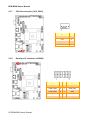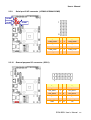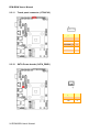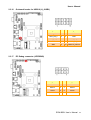
1
ECM-BSW Intel® Pentium® /Celeron® Processor 3.5” Micro Module User’s Manual 1st Ed – 14 August 2015 Part No. E2047392600R ECM-BSW User’s Manual FCC Statement THIS DEVICE COMPLIES WITH PART 15 FCC RULES. OPERATION IS SUBJECT TO THE FOLLOWING TWO CONDITIONS: (1) THIS DEVICE MAY NOT CAUSE HARMFUL INTERFERENCE. (2) THIS DEVICE MUST ACCEPT ANY INTERFERENCE RECEIVED INCLUDING INTERFERENCE THAT MAY CAUSE UNDESIRED OPERATION. THIS EQUIPMENT HAS BEEN TESTED AND FOUND TO COMPLY WITH THE LIMITS FOR A CLASS "A" DIGITAL DEVICE, PURSUANT TO PART 15 OF THE FCC RULES. THESE LIMITS ARE DESIGNED TO PROVIDE REASONABLE PROTECTION AGAINST HARMFUL INTERFERENCE WHEN THE EQUIPMENT IS OPERATED IN A COMMERCIAL ENVIRONMENT. THIS EQUIPMENT GENERATES, USES, AND CAN RADIATE RADIO FREQUENCY ENERGY AND, IF NOT INSTALLED AND USED IN ACCORDANCE WITH THE INSTRUCTION MANUAL, INTERFERENCE TO RADIO COMMUNICATIONS. MAY CAUSE HARMFUL OPERATION OF THIS EQUIPMENT IN A RESIDENTIAL AREA IS LIKELY TO CAUSE HARMFUL INTERFERENCE IN WHICH CASE THE USER WILL BE REQUIRED TO CORRECT THE INTERFERENCE AT HIS OWN EXPENSE. Notice This guide is designed for experienced users to setup the system within the shortest time. For detailed information, please always refer to the electronic user's manual. Copyright Notice Copyright 2015 Avalue Technology Inc., ALL RIGHTS RESERVED. No part of this document may be reproduced, copied, translated, or transmitted in any form or by any means, electronic or mechanical, for any purpose, without the prior written permission of the original manufacturer. Trademark Acknowledgement Brand and product names are trademarks or registered trademarks of their respective owners. Disclaimer Avalue Technology Inc. reserves the right to make changes, without notice, to any product, including circuits and/or software described or contained in this manual in order to improve design and/or performance. Avalue Technology assumes no responsibility or liability for the use of the described product(s), conveys no license or title under any patent, copyright, or masks work rights to these products, and makes no representations or warranties that 2 ECM-BSW User’s Manual User’s Manual these products are free from patent, copyright, or mask work right infringement, unless otherwise specified. Applications that are described in this manual are for illustration purposes only. Avalue Technology Inc. makes no representation or warranty that such application will be suitable for the specified use without further testing or modification. Life Support Policy Avalue Technology’s PRODUCTS ARE NOT FOR USE AS CRITICAL COMPONENTS IN LIFE SUPPORT DEVICES OR SYSTEMS WITHOUT THE PRIOR WRITTEN APPROVAL OF Avalue Technology Inc. As used herein: 1. Life support devices or systems are devices or systems which, (a) are intended for surgical implant into body, or (b) support or sustain life and whose failure to perform, when properly used in accordance with instructions for use provided in the labeling, can be reasonably expected to result in significant injury to the user. 2. A critical component is any component of a life support device or system whose failure to perform can be reasonably expected to cause the failure of the life support device or system, or to affect its safety or effectiveness. A Message to the Customer Avalue Customer Services Each and every Avalue’s product is built to the most exacting specifications to ensure reliable performance in the harsh and demanding conditions typical of industrial environments. Whether your new Avalue device is destined for the laboratory or the factory floor, you can be assured that your product will provide the reliability and ease of operation for which the name Avalue has come to be known. Your satisfaction is our primary concern. Here is a guide to Avalue’s customer services. To ensure you get the full benefit of our services, please follow the instructions below carefully. Technical Support We want you to get the maximum performance from your products. So if you run into technical difficulties, we are here to help. For the most frequently asked questions, you can easily find answers in your product documentation. These answers are normally a lot more detailed than the ones we can give over the phone. So please consult the user’s manual first. To receive the latest version of the user’s manual; please visit our Web site at: http://www.avalue.com.tw/ ECM-BSW User’s Manual 3 ECM-BSW User’s Manual Product Warranty Avalue warrants to you, the original purchaser, that each of its products will be free from defects in materials and workmanship for two years from the date of purchase. This warranty does not apply to any products which have been repaired or altered by persons other than repair personnel authorized by Avalue, or which have been subject to misuse, abuse, accident or improper installation. Avalue assumes no liability under the terms of this warranty as a consequence of such events. Because of Avalue’s high quality-control standards and rigorous testing, most of our customers never need to use our repair service. If any of Avalue’s products is defective, it will be repaired or replaced at no charge during the warranty period. For out-of-warranty repairs, you will be billed according to the cost of replacement materials, service time, and freight. Please consult your dealer for more details. If you think you have a defective product, follow these steps: 1. Collect all the information about the problem encountered. (For example, CPU type and speed, Avalue’s products model name, hardware & BIOS revision number, other hardware and software used, etc.) Note anything abnormal and list any on-screen messages you get when the problem occurs. 2. Call your dealer and describe the problem. Please have your manual, product, and any helpful information available. 3. If your product is diagnosed as defective, obtain an RMA (return material authorization) number from your dealer. This allows us to process your good 4. return more quickly. Carefully pack the defective product, a complete Repair and Replacement Order Card and a photocopy proof of purchase date (such as your sales receipt) in a shippable container. A product returned without proof of the 5. purchase date is not eligible for warranty service. Write the RMA number visibly on the outside of the package and ship it prepaid to your dealer. 4 ECM-BSW User’s Manual User’s Manual Content 1. Getting Started .................................................................................................... 8 1.1 1.2 Safety Precautions ............................................................................................. 8 Packing List ....................................................................................................... 8 1.3 1.4 Document Amendment History............................................................................ 9 Manual Objectives............................................................................................ 10 1.5 1.6 System Specifications ...................................................................................... 11 Architecture Overview—Block Diagram ............................................................. 13 2. Hardware Configuration .................................................................................... 14 2.1 Product Overview............................................................................................. 15 2.2 2.3 Jumper and Connector List ............................................................................... 17 Setting Jumpers & Connectors .......................................................................... 19 2.3.1 AT/ ATX Input power select (JAT1) ........................................................................................ 19 2.3.2 Serial port 1 pin9 signal select (JRI1) ..................................................................................... 19 2.3.3 Clear CMOS (JBAT1) ............................................................................................................ 20 2.3.4 LCD backlight brightness adjustment (JBKL_SEL1) ................................................................ 20 2.3.5 LCD Inverter connector (JBKL1) ............................................................................................ 21 2.3.6 LCD Backlight VR/Push Up/Push Down header (JBLKCTL) ..................................................... 21 2.3.7 CPU fan connector (CPU_FAN1) ........................................................................................... 22 2.3.8 Serial port 2 connector (JCOM2) ............................................................................................ 22 2.3.9 Serial port 3/4/5 connector (JCOM3/JCOM4/JCOM5) .............................................................. 23 2.3.10 General purpose I/O connector (JDIO1) ............................................................................. 23 2.3.11 Touch panel connector (JTOUCH1) ................................................................................... 24 2.3.12 SATA Power header (SATA_PWR1) .................................................................................. 24 2.3.13 Power connector (PWR1) .................................................................................................. 25 2.3.14 LPC connector (JLPC1)..................................................................................................... 25 2.3.15 LVDS connector (JLVDS) .................................................................................................. 26 2.3.16 On-board header for USB2.0 (H_JUSB1) ........................................................................... 27 2.3.17 EC Debug connector (JECDBUG) ...................................................................................... 27 2.3.18 PS/2 keyboard & mouse header (JKBMS1) ........................................................................ 28 2.3.19 Serial port 1 in RS-422/485 mode (J422_485)..................................................................... 28 2.3.20 Miscellaneous setting connector (JFP1) ............................................................................. 29 2.3.21 BIOS SPI header (BIOS_SPI1) .......................................................................................... 29 2.3.22 PC Buzzer header (JBZ1).................................................................................................. 30 2.3.23 Battery connector (BT1) .................................................................................................... 30 2.3.24 Audio connector (JAUDIO1)............................................................................................... 31 2.3.24.1 Signal Description – Audio connector (JAUDIO1) ............................................................ 31 ECM-BSW User’s Manual 5 ECM-BSW User’s Manual 2.3.25 VGA header (JVGA1) ........................................................................................................ 32 3.BIOS Setup ............................................................................................................ 33 3.1 Introduction...................................................................................................... 34 3.2 3.3 Starting Setup .................................................................................................. 34 Using Setup ..................................................................................................... 35 3.4 3.5 Getting Help .................................................................................................... 36 In Case of Problems ......................................................................................... 36 3.6 BIOS setup ...................................................................................................... 37 3.6.1 Main Menu ........................................................................................................................... 37 3.6.1.1 System Time ................................................................................................................ 37 3.6.1.2 System Date ................................................................................................................. 37 3.6.2 Advanced Menu .................................................................................................................... 38 3.6.2.1 SATA Configuration ...................................................................................................... 39 3.6.2.2 PCI Express Configuration............................................................................................. 39 3.6.2.3 RTC S5 Wake............................................................................................................... 40 3.6.2.4 Hardware Monitor ......................................................................................................... 41 3.6.2.5 SIO NUVOTON5104D................................................................................................... 41 3.6.2.6 Brightness Control ........................................................................................................ 42 3.6.2.7 Device function Control ................................................................................................. 43 3.6.3 Security .............................................................................................................................. 43 3.6.4 Power................................................................................................................................. 44 3.6.5 Boot ................................................................................................................................... 45 3.6.6 Exit..................................................................................................................................... 46 3.6.6.1 Exit Saving Changes ..................................................................................................... 46 3.6.6.2 Save Change Without Exit ............................................................................................. 46 3.6.6.3 Exit Discarding Changes ............................................................................................... 46 3.6.6.4 Load Optimal Defaults ................................................................................................... 46 3.6.6.5 Load Custom Defaults ................................................................................................... 46 3.6.6.6 Save Custom Defaults................................................................................................... 46 3.6.6.7 Discard Changes .......................................................................................................... 46 4. Drivers Installation ............................................................................................... 47 4.1 Install Chipset Driver ........................................................................................ 48 4.2 4.3 Install Nuvoton Driver ....................................................................................... 49 Install TXE Driver ............................................................................................. 50 4.4 4.5 Install VGA Driver ............................................................................................ 51 Install Audio Driver (For Realtek ALC233).......................................................... 52 4.6 4.7 Install USB3.0 Driver ........................................................................................ 53 Install Ethernet Driver ....................................................................................... 54 4.8 4.9 Install Serial IO Driver....................................................................................... 55 Install SMSC Hub Driver ................................................................................... 56 6 ECM-BSW User’s Manual 4.10 User’s Manual Install Touch Driver .......................................................................................... 57 5. Mechanical Drawing ............................................................................................. 59 ECM-BSW User’s Manual 7 ECM-BSW User’s Manual 1. Getting Started 1.1 Safety Precautions Warning! Always completely disconnect the power cord from your chassis whenever you work with the hardware. Do not make connections while the power is on. Sensitive electronic components can be damaged by sudden power surges. Only experienced electronics personnel should open the PC chassis. Caution! Always ground yourself to remove any static charge before touching the CPU card. Modern electronic devices are very sensitive to static electric charges. As a safety precaution, use a grounding wrist strap at all times. Place all electronic components in a static-dissipative surface or static-shielded bag when they are not in the chassis. 1.2 Packing List Before you begin installing your single board, please make sure that the following materials have been shipped: 1 x 3.5” ECM-BSW Micro Module 1 x DVD-ROM contains the followings: — User’s Manual (this manual in PDF file) — — — Audio drivers and utilities 1 x Cable set contains the followings: — — Ethernet driver and utilities VGA drivers and utilities 1 x Serial ATA cable (7-pin, standard) 1 x Wire SATA power cable (15-pin, 2P/2.0mm) — 1 x Flat Cable 9P(M)-PHD (10P/2.0mm) 3M foam (VHB-4622 10mm*20mm*1.1mm) 8 ECM-BSW User’s Manual User’s Manual 1.3 Document Amendment History Revision st 1 Date By August 2015 Avalue Comment Initial Release ECM-BSW User’s Manual 9 ECM-BSW User’s Manual 1.4 Manual Objectives This manual describes in details Avalue Technology ECM-BSW Single Board. We have tried to include as much information as possible but we have not duplicated information that is provided in the standard IBM Technical References, unless it proved to be necessary to aid in the understanding of this board. We strongly recommend that you study this manual carefully before attempting to set up ECM-BSW or change the standard configurations. Whilst all the necessary information is available in this manual we would recommend that unless you are confident, you contact your supplier for guidance. Please be aware that it is possible to create configurations within the CMOS RAM that make booting impossible. If this should happen, clear the CMOS settings, (see the description of the Jumper Settings for details). If you have any suggestions or find any errors regarding this manual and want to inform us of these, please contact our Customer Service department with the relevant details. 10 ECM-BSW User’s Manual User’s Manual 1.5 System Specifications System CPU Intel® Pentium® /Celeron® processor N3000 series for mobile BIOS Insyde BIOS, 64 Mbit SPI Flash ROM System Chipset Braswell SoC integrated I/O Chip System Memory SSD Watchdog Timer H/W Status Monitor Expansion Built-in Touch screen (optional) I/O Nuvoton NPCE388N 1 x 204-pin DDR3L 1600 SODIMM up to 8G (non ECC) (If 1333 MHz DIMM is installed, it will run at 1066 MHz) mSATA (from MiniPCIe) H/W Reset, 1sec. ~ 65535sec and 1sec. or 1min./step CPU & system temperature monitoring Voltages monitoring 1 x Full-Size Mini PCI Express Mini Card with mSATA supported 1 x Half-size Mini PCIe EETI ETP-CP-MER4485XRU With 5-pin 2.0mm Box Header (Can be Selected to Support 4/ 5Wire Touch Screen) 1 x SATA III MIO 1 x DB-9 male connector for COM1 supports RS232/422/485 (selectable by BIOS, w/ Auto Flow) USB 4 x USB3.0 (Edge connectors), 2 x USB 2.0 (Pin header) GPIO 8-bit Others LPC, SPI Display Chipset Braswell SoC integrated Graphics HDMI mode: 1920x1080@60Hz Resolution LVDS mode:1920x1080@60Hz VGA by pin header (optional) Multiple Display HDMI + LVDS HDMI HDMI x1.4b LCD Dual channel 18/24-bit LVDS Interface LVDS via Realtek RTD2136N Audio AC97 Codec Audio Amp Realtek ALC233 HD Audio support 2.1-CH 2W Ethernet ECM-BSW User’s Manual 11 ECM-BSW User’s Manual 2 x RealTek RTL8119I LAN Chip Ethernet Interface 10/100/1000 Base-Tx compatible Internal I/O Connectors Fan Buzzer CPU_FAN1 4pin 2.5mm wafer header With Pin header CMOS Battery CR2032 Power On Audio COM AX / ATX selectable by jumper 8 x 2 pin header w/2.0mm pitch With AMP_L+/-, AMP_R+/4 x RS232 (Pin header) for COM2/3/4/5 Rear I/O Connectors USB 4 x USB3.0 LAN 2 x RJ-45 HDMI 1 x HDMI (HDMI 19P 90D(F) STD w/Flange BLK) LED Stack LED indicator for power / HDD Mechanical & Environmental Power Requirement ACPI Power Type Operating Temp. +11.4V ~ +26V Single power ATX Support S0, S3, S4, S5 ACPI 5.0 Compliant AT / ATX 0°C ~ 60°C Storage Temp. -40°C ~ 75°C Operating Humidity Size (L x W) Weight OS support 0% ~ 90% relative humidity, non-condensing 5.7" x 4" (146mm x 101mm) 0.44lbs (0.2kg) Windows 10/ 8.1 / Windows 7 / Linux Note: Specifications are subject to change without notice. 12 ECM-BSW User’s Manual User’s Manual 1.6 Architecture Overview—Block Diagram The following block diagram shows the architecture and main components of ECM-BSW. ECM-BSW User’s Manual 13 ECM-BSW User’s Manual 2. Hardware Configuration 14 ECM-BSW User’s Manual User’s Manual 2.1 Product Overview ECM-BSW User’s Manual 15 ECM-BSW User’s Manual 16 ECM-BSW User’s Manual User’s Manual 2.2 Jumper and Connector List You can configure your board to match the needs of your application by setting jumpers. A jumper is the simplest kind of electric switch. It consists of two metal pins and a small metal clip (often protected by a plastic cover) that slides over the pins to connect them. To “close” a jumper you connect the pins with the clip. To “open” a jumper you remove the clip. Sometimes a jumper will have three pins, labeled 1, 2, and 3. In this case, you would connect either two pins. The jumper settings are schematically depicted in this manual as follows: A pair of needle-nose pliers may be helpful when working with jumpers. Connectors on the board are linked to external devices such as hard disk drives, a keyboard, or floppy drives. In addition, the board has a number of jumpers that allow you to configure your system to suit your application. If you have any doubts about the best hardware configuration for your application, contact your local distributor or sales representative before you make any changes. The following tables list the function of each of the board’s jumpers and connectors. Jumpers Label Function Note JBAT1 Clear CMOS 3 x 1 header, pitch 2.00 mm JRI1 Serial port 1 pin9 signal select 3 x 2 header, pitch 2.00 mm JAT1 AT/ ATX Input power select 3 x 1 header, pitch 2.00 mm JBKL_SEL1 LCD backlight brightness adjustment 3 x 2 header, pitch 2.00 mm Label Function Note BT1 Battery connector 2 x 1 wafer, pitch 1.25 mm CPU_FAN1 CPU fan connector 4 x 1 wafer, pitch 2.54 mm JAUDIO1 Audio connector 8 x 2 header, pitch 2.00 mm JBKL1 LCD inverter connector 5 x 1 wafer, pitch 2.00 mm Connectors ECM-BSW User’s Manual 17 ECM-BSW User’s Manual J422_485 COM1 Serial port 1 in RS-422/485 mode 3 x 2 header, pitch 2.00 mm Serial port 1 connector D-sub 9-pin, male Note:COM1 support RS422/485 by BIOS setting JCOM2/3/4/5 Serial port 2/3/4/5 connector 5 x 2 header, pitch 2.00 mm JDIO1 General purpose I/O connector 6 x 2 header, pitch 2.00 mm JFP1 Miscellaneous setting connector 5 x 2 header, pitch 2.00 mm JLPC1 Low pin count interface 5 x 2 header, pitch 2.00 mm JLVDS1 LVDS connector 20 x 2 header, pitch 1.25 mm JTOUCH1 Touch Panel connector 5 x 1 wafer, pitch 2.00 mm USB12/34 On-board connector for USB3.0 x 4 H_JUSB1 On-board header for USB2.0 5 x 2 header, pitch 2.00 mm JECDBUG1 EC Debug connector 4 x 2 header, pitch 2.00 mm LAN1 RJ-45 Ethernet connector x 2 LED1 HDD/Power LED indicator PWR1 Power connector 2 x 2 wafer, pitch 4.20 mm JKBMS1 PS/2 keyboard & mouse header 3 x 2 header, pitch 2.00 mm SATA_PWR1 SATA power header 2 x 1 wafer, pitch 2.00 mm SATA1 Serial ATA connector 1 JVGA1 VGA header (optional) 8 x 2 wafer, pitch 2.00 mm BIOS_SPI1 BIOS SPI header 4 x 2 header, pitch 2.00 mm MINI_PCIE1/2 Mini-PCI connector 1/2 SO_DIMM1 DDR3 SODIMM connector JBZ1 PC Buzzer header JBLKCTL LCD Backlight VR/Push Up/Push Down 3 x 2 header, pitch 2.00mm header 18 ECM-BSW User’s Manual 2 x 1 wafer, pitch 2.00 mm User’s Manual 2.3 Setting Jumpers & Connectors 2.3.1 AT/ ATX Input power select (JAT1) AT* ATX 2.3.2 Serial port 1 pin9 signal select (JRI1) Ring* +12V +5V * Default ECM-BSW User’s Manual 19 ECM-BSW User’s Manual 2.3.3 Clear CMOS (JBAT1) Protect* Clear CMOS * Default 2.3.4 LCD backlight brightness adjustment (JBKL_SEL1) * Default 20 ECM-BSW User’s Manual PWM Mode* OS Driver Control DC Mode VR Control* User’s Manual 2.3.5 LCD Inverter connector (JBKL1) Signal PIN +5V 5 VBRIGHT 4 BKLEN 3 GND 2 +12V 1 Note: For inverters with adjustable Backlight function, it is possible to control the LCD brightness through the VR signal controlled by JBLKCTL. Please see the JBLKCTL section for detailed circuitry information. 2.3.6 LCD Backlight VR/Push Up/Push Down header (JBLKCTL) Signal PIN PIN Signal GND 6 5 BLK_BRI_DN GND 4 3 BLK_BRI_UP GND 2 1 BLK_VR_MOD ECM-BSW User’s Manual 21 ECM-BSW User’s Manual 2.3.7 2.3.8 CPU fan connector (CPU_FAN1) Signal PIN GND 1 +12V 2 EC_TACH0 3 FAN_PWM1 4 Serial port 2 connector (JCOM2) Signal 22 ECM-BSW User’s Manual PIN PIN Signal COM_RXD# 2 1 COM_DCD# COM_DTR# 4 3 COM_TXD COM_DSR# 6 5 GND COM_CTS# 8 7 COM_RTS# NC 10 9 COM_RI# User’s Manual 2.3.9 Serial port 3/4/5 connector (JCOM3/JCOM4/JCOM5) JCOM5 JCOM4 JCOM3 Signal 2.3.10 PIN PIN Signal COM_DCD# 1 2 COM_RXD# COM_TXD 3 4 COM_DTR# GND 5 6 COM_DSR# COM_RTS# 7 8 COM_CTS# COM_RI# 9 10 NC General purpose I/O connector (JDIO1) Signal PIN PIN Signal DIO_GP20 1 2 DIO_GP10 DIO_GP21 3 4 DIO_GP11 DIO_GP22 5 6 DIO_GP12 DIO_GP23 7 8 DIO_GP13 SMB_CLK_9555 9 10 SMB_DATA_9555 GND 11 12 +5V ECM-BSW User’s Manual 23 ECM-BSW User’s Manual 2.3.11 2.3.12 Touch panel connector (JTOUCH1) Signal PIN THX+ 1 THX- 2 THPROBE_R 3 THY+ 4 THY- 5 Signal PIN GND 1 +5V 2 SATA Power header (SATA_PWR1) 24 ECM-BSW User’s Manual User’s Manual 2.3.13 2.3.14 Power connector (PWR1) Signal PIN PIN Signal GND 1 2 GND +26V 3 4 +26V LPC connector (JLPC1) Signal PIN PIN Signal LPC_AD0 1 2 +3.3V LPC_AD1 3 4 LPC_PORT80_RST# LPC_AD 5 6 LPC_FRAME# LPC_AD03 7 8 LPC_PORT80_CLK LPC_SERIRQ 9 10 GND ECM-BSW User’s Manual 25 ECM-BSW User’s Manual 2.3.15 LVDS connector (JLVDS) Signal 26 ECM-BSW User’s Manual PIN PIN Signal +5V 2 1 +3.3V +5V 4 3 +3.3V PANEL_DDC_DAT 6 5 PANEL_DDC_CLK GND 8 7 GND LVDS_DATA0_P 10 9 LVDS_DATA1_P LVDS_DATA0_N 12 11 LVDS_DATA1_N GND 14 13 GND LVDS_DATA2_P 16 15 LVDS_DATA3_P LVDS_DATA2_N 18 17 LVDS_DATA3_N GND 20 19 GND LVDS_DATA4_P 22 21 LVDS_DATA5_P LVDS_DATA4_N 24 23 LVDS_DATA5_N GND 26 25 GND LVDS_DATA6_P 28 27 LVDS_DATA7_P LVDS_DATA6_N 30 29 LVDS_DATA7_N GND 32 31 GND LVDS_CLK1_P 34 33 LVDS_CLK2_P LVDS_CLK1_N 36 35 LVDS_CLK2_N GND 38 37 GND +12V 40 39 +12V User’s Manual 2.3.16 On-board header for USB2.0 (H_JUSB1) Signal 2.3.17 PIN PIN Signal USBVCC_HSIC12 1 2 GND HSIC_DN_2 3 4 GND HSIC_DP_2 5 6 HSIC_DP_1 GND 7 8 HSIC_DN_1 GND 9 10 USBVCC_HSIC12 EC Debug connector (JECDBUG) Signal PIN PIN Signal KSO0 1 2 KSO12 KSO13 3 4 KSO14 KSO5 5 6 KSO6 GND 7 8 NC ECM-BSW User’s Manual 27 ECM-BSW User’s Manual 2.3.18 PS/2 keyboard & mouse header (JKBMS1) Signal 2.3.19 PIN PIN Signal MSCK 6 5 MSDT KBVCC 4 3 GND KBCK 2 1 KBDT Serial port 1 in RS-422/485 mode (J422_485) Signal 28 ECM-BSW User’s Manual PIN PIN Signal 485TX2- 1 2 485RX2- 485TX2+ 3 4 485RX2+ +5V 5 6 GND User’s Manual 2.3.20 Miscellaneous setting connector (JFP1) Signal 2.3.21 PIN PIN Signal +3VLP 1 2 GND PMU_RSTBTN# 3 4 GND FP_PWR_LED+ 5 6 PWR_LED# HDD_LED# 7 8 +5V NC 9 10 NC BIOS SPI header (BIOS_SPI1) Signal PIN PIN Signal NC 8 7 SPI_HOLD# SPI_MOSI 6 5 SPI_MISO CPI_CLK 4 3 SPI_CS#0 GND 2 1 +1.8VSB ECM-BSW User’s Manual 29 ECM-BSW User’s Manual 2.3.22 2.3.23 PC Buzzer header (JBZ1) Signal PIN +5V 2 SOC_SPKR_R 1 Signal PIN +RTCBATT 2 GND 1 Battery connector (BT1) 30 ECM-BSW User’s Manual User’s Manual 2.3.24 Audio connector (JAUDIO1) Signal PIN PIN Signal SPK_R- 16 15 SPK_L- SPK_R+ 14 13 SPK_L+ HD_AGND 12 11 MIC1-JD LINE1-JD 10 9 FRONT-JD MIC1-L-IN 8 7 MIC1-R-IN LIN1-L-IN 6 5 LINE1-R-IN HD_AGND 4 3 HD_AGND FRONT-L-OUT 2 1 FRONT-R-OUT 2.3.24.1 Signal Description – Audio connector (JAUDIO1) Signal Signal Description LINE1-JD AUDIO IN (LINE_RIN/LIN)sense pin FRONT-JD AUDIO Out(ROUT/LOUT) sense pin MIC1-JD MIC IN (MIC_RIN/LIN) sense pin ECM-BSW User’s Manual 31 ECM-BSW User’s Manual 2.3.25 VGA header (JVGA1) Signal 32 ECM-BSW User’s Manual PIN PIN Signal +5V 1 2 VGA_RED GND 3 4 VGA_GREEN NC 5 6 VGA_BLUE VGA_DDCDAT 7 8 NC VGA_HSYNC_R 9 10 GND VGA_VSYNC_R 11 12 GND VGA_DDCCLK 13 14 GND GND 15 16 GND User’s Manual 3.BIOS Setup ECM-BSW User’s Manual 33 ECM-BSW User’s Manual 3.1 Introduction The BIOS setup program allows users to modify the basic system configuration. In this following chapter will describe how to access the BIOS setup program and the configuration options that may be changed. 3.2 Starting Setup Insyde BIOS™ is immediately activated when you first power on the computer. The BIOS reads the system information contained in the NVRAM and begins the process of checking out the system and configuring it. When it finishes, the BIOS will seek an operating system on one of the disks and then launch and turn control over to the operating system. While the BIOS is in control, the Setup program can be activated in one of two ways: By pressing <F2> immediately after switching the system on, or By pressing the <F2> key when the following message appears briefly at the left-top of the screen during the POST (Power On Self Test). Press <F2> to enter SETUP If the message disappears before you respond and you still wish to enter Setup, restart the system to try again by turning it OFF then ON or pressing the "RESET" button on the system case. You may also restart by simultaneously pressing <Ctrl>, <Alt>, and <Delete> keys. 34 ECM-BSW User’s Manual User’s Manual 3.3 Using Setup In general, you use the arrow keys to highlight items, press <Enter> to select, use the PageUp and PageDown keys to change entries, press <F1> for help and press <Esc> to quit. The following table provides more detail about how to navigate in the Setup program using the keyboard. Button Description ↑ Move to previous item ↓ Move to next item ← Move to the item in the left hand → + key Move to the item in the right hand Main Menu -- Quit and not save changes into NVRAM Status Page Setup Menu and Option Page Setup Menu -- Exit current page and return to Main Menu Increase the numeric value or make changes - key Decrease the numeric value or make changes F1 key General help, only for Status Page Setup Menu and Option Page Setup Menu F9 key Optimized defaults F10 key Save & Exit Setup Esc key Navigating Through The Menu Bar Use the left and right arrow keys to choose the menu you want to be in. Note: Some of the navigation keys differ from one screen to another. To Display a Sub Menu Use the arrow keys to move the cursor to the sub menu you want. Then press <Enter>. A “” pointer marks all sub menus. ECM-BSW User’s Manual 35 ECM-BSW User’s Manual 3.4 Getting Help Press F1 to pop up a small help window that describes the appropriate keys to use and the possible selections for the highlighted item. To exit the Help Window press <Esc> or the F1 key again. 3.5 In Case of Problems If, after making and saving system changes with Setup, you discover that your computer no longer is able to boot, the Insyde BIOS supports an override to the NVRAM settings which resets your system to its defaults. The best advice is to only alter settings which you thoroughly understand. To this end, we strongly recommend that you avoid making any changes to the chipset defaults. These defaults have been carefully chosen by both BIOS Vendor and your systems manufacturer to provide the absolute maximum performance and reliability. Even a seemingly small change to the chipset setup has the potential for causing you to use the override. 36 ECM-BSW User’s Manual User’s Manual 3.6 BIOS setup Once you enter the InsydeH2O Setup Utility, the Main Menu will appear on the screen. The Main Menu allows you to select from several setup functions and exit choices. Use the arrow keys to select among the items and press <Enter> to accept and enter the sub-menu. 3.6.1 Main Menu This section allows you to record some basic hardware configurations in your computer and set the system clock. 3.6.1.1 System Time Use the system time option to set the system time. Manually enter the hours, minutes and seconds. 3.6.1.2 System Date Use the system date option to set the system date. Manually enter the day, month and year. Note: The BIOS setup screens shown in this chapter are for reference purposes only, and may not exactly match what you see on your screen. Visit the Avalue website (www.avalue.com.tw) to download the latest product and BIOS information. ECM-BSW User’s Manual 37 ECM-BSW User’s Manual 3.6.2 Advanced Menu This section allows you to configure your CPU and other system devices for basic operation through the following sub-menus. Item Watch Dog Panel Type Select Options Disabled[Default], 30 sec 40 sec 50 sec 1 min 2 min 10 min 30 min 1024x768 24/1[Default] 800x600 18/1 1024x768 18/1 1366x768 18/1 1024x600 18/1 1280x800 18/1 1920x1200 24/2 640x480 18/1 800x480 18/1 1920x1080 18/2 1280x1024 24/2 1440x900 18/2 1600x1200 24/2 1366x768 24/1 1920x1080 24/2 1680x1050 24/2 38 ECM-BSW User’s Manual Description Select WatchDog items. Select Panel Type for display. User’s Manual 3.6.2.1 SATA Configuration Item SATA Controller SATA Interface Speed Options Disabled, Enabled[Default] Gen1 Gen2 Gen3[Default] Description SATA Controller. Select SATA Interface Speed. 3.6.2.2 PCI Express Configuration ECM-BSW User’s Manual 39 ECM-BSW User’s Manual Item Options PCI Express Root Port 1/2/3/4 Disabled Enabled[Default], ASPM L1 Substates PCIe Speed Disabled[Default] L0s L1 L0sL1 Disabled[Default] L1.1 & L1.2 L1.1 L1.2 Auto[Default] Gen 1 Gen 2 Description Control the PCI Express Root Port. If disable PCIE port 1, another PCIE port will be disabled. PCI Express Active State Power Management settings. PCI Express L1 Substates settings. Configure PCIe Speed. 3.6.2.3 RTC S5 Wake Item Wake up day of week Time 40 ECM-BSW User’s Manual Options Monday-Friday Monday-Saturday Every Day Disabled[Default] [00:00:00][Default] Description Select wake up day of week. This is the help for the hour, minute second field. Valid range is from 0 to 23, 0 to 59, 0 to 59. INCREASE/REDUCE : +/-. User’s Manual 3.6.2.4 Hardware Monitor 3.6.2.5 SIO NUVOTON5104D ECM-BSW User’s Manual 41 ECM-BSW User’s Manual 3.6.2.6 Brightness Control Item Brightness Control Backlight brightness LVDS Back Light PWM Frequency 42 ECM-BSW User’s Manual Options VR BIOS[Default] 0% 25% 50% 75% 100%[Default] 200[Default] 300 400 500 700 1k 2k 3k 5k 10k 20k Description LCD Brightness is controlled by BIOS or VR. Backlight brightness percentage. LVDS Back Light PWM Frequency. User’s Manual 3.6.2.7 Device function Control Item COM1 function select 3.6.3 Options RS232[Default] RS422 RS485 Description Select COM1 function as RS232/422/485. Security ECM-BSW User’s Manual 43 ECM-BSW User’s Manual Item TPM Operation Options No Operation[Default] Disable and Deactivate Enable and Activate Description Enable/Disable TPM Function. This option will automatically return to No-Operation. Set Supervisor Password. Install or Change the password and the length of Set Supervisor Password 3.6.4 password must be greater than on character Power Item Erp Function AC Loss Resume Turbo Mode USB Power C-States 44 ECM-BSW User’s Manual Option Disabled[Default] Enabled Disabled[Default] Enabled Disabled Enabled[Default] Disabled Enabled[Default] Disabled Enabled[Default] Description ErP Function (Deep S5). AC Loss Resume setting. Enable processor Turbo Mode(requires EMTTM enabled too). USB Power on standby. Enable processor idle power saving states (C-States). User’s Manual 3.6.5 Boot Item Boot Type Option Legacy Boot Type UEFI Boot Type[Default] Quick Boot Disabled[Default] Enabled Quiet Boot Disabled Enabled[Default] Network Stack Disabled[Default] Enabled Add Boot Options First Auto[Default] Description Select boot type to Legacy type or UEFI type. Allows InsydeH20 to skip certain tests while booting. This will decrease the time needed to boot the system. Disables or enables booting in Text Mode. Network Stack Support: Windows 8 BitLocker Unlock UEFI IPv4/ IPv6 PXE Legacy PXE OPROM. Position in Boot Order for Shell, Network and Removables. ECM-BSW User’s Manual 45 ECM-BSW User’s Manual 3.6.6 Exit 3.6.6.1 Exit Saving Changes Exit system setup and save your changers. 3.6.6.2 Save Change Without Exit Save your changes and without exiting system. 3.6.6.3 Exit Discarding Changes Exit system setup and without saving your changes. 3.6.6.4 Load Optimal Defaults Load Optimal Defaults. 3.6.6.5 Load Custom Defaults Load Custom Defaults. 3.6.6.6 Save Custom Defaults Save Custom Defaults. 3.6.6.7 Discard Changes Discard Changes. 46 ECM-BSW User’s Manual User’s Manual 4. Drivers Installation Note: Installation procedures and screen shots in this section are for your reference and may not be exactly the same as shown on your screen. ECM-BSW User’s Manual 47 ECM-BSW User’s Manual 4.1 Install Chipset Driver Insert the Supporting DVD-ROM to DVD-ROM drive, and it should show the index page of Avalue’s products automatically. If not, locate Index.htm and choose the product from the menu left, or link to \Driver_Chipset\Intel\ECM-BSW. Note: The installation procedures and screen shots in this section are based on Windows 8.1 operation system. If the warning message appears while the installation process, click Continue to go on. Step1. Click Next. Step 2. Click Accept. 48 ECM-BSW User’s Manual Step 3. Click Install. Step 4. Click Finish to complete setup. User’s Manual 4.2 Install Nuvoton Driver Insert the Supporting DVD-ROM to DVD-ROM drive, and it should show the index page of Avalue’s products automatically. If not, locate Index.htm and choose the product from the menu left, or link to \Utility\ECM-BSW_Nuvoton. Note: The installation procedures and screen shots in this section are based on Windows 8.1 operation system. If the warning message appears while the installation process, click Continue to go on. Step 3. Click Finish to complete setup. Step1. Click Next to start installation. Step 2. Click Install to proceed setup. ECM-BSW User’s Manual 49 ECM-BSW User’s Manual 4.3 Install TXE Driver Insert the Supporting DVD-ROM to DVD-ROM drive, and it should show the index page of Avalue’s products automatically. If not, locate Index.htm and choose the product from the menu left, or link to \Utility\ECM-BSW_TXE. Note: The installation procedures and screen shots in this section are based on Windows 8.1 operation system. If the warning message appears while the installation process, click Continue to go on. Step 3. Click Next to continue installation. Step 4. Click Install to complete setup. Step1. Click Next to start installation. Step 2. Click Next. 50 ECM-BSW User’s Manual Step 5. Click Finish to complete setup. User’s Manual 4.4 Install VGA Driver Insert the Supporting DVD-ROM to DVD-ROM drive, and it should show the index page of Avalue’s products automatically. If not, locate Index.htm and choose the product from the menu left, or link to \VGA\ECM-BSW. Note: The installation procedures and screen shots in this section are based on Windows 8.1 operation system. Step 3. Click Next. Step 1. Click Next to continue installation. Step 2. Step 4. Click Next. Step 5. Click Finish to complete setup. Click Yes to accept license agreement. ECM-BSW User’s Manual 51 ECM-BSW User’s Manual 4.5 Install Audio Driver (For Realtek ALC233) Insert the Supporting CD-ROM to CD-ROM drive, and it should show the index page of Avalue’s products automatically. If not, locate Index.htm and choose the product from the menu left, or link to \Driver_Audio\Realtek\ALC233\ECM-BSW_Audio. Note: The installation procedures and screen shots in this section are based on Windows 8.1 operation system. Step 1. Click Next to continue setup. Step 2. Click Finish to complete the setup. 52 ECM-BSW User’s Manual User’s Manual 4.6 Install USB3.0 Driver Insert the Supporting CD-ROM to CD-ROM drive, and it should show the index page of Avalue’s products automatically. If not, locate Index.htm and choose the product from the menu left, or link to \Utility\ECM-BSW_USB3.0. Note: The installation procedures and screen shots in this section are based on Windows 8.1 operation system. Step 3. Click Next Step 1. Click Next to continue setup. Step 4. Click Finish to complete the setup Step 2. Click Next. ECM-BSW User’s Manual 53 ECM-BSW User’s Manual 4.7 Install Ethernet Driver Insert the Supporting DVD-ROM to DVD-ROM drive, and it should show the index page of Avalue’s products automatically. If not, locate Index.htm and choose the product from the menu left, or link to \Driver_Gigabit\Realtek\RTL8119\ECM-BSW_LAN. Note: The installation procedures and screen shots in this section are based on Windows 8.1 operation system. Step 3. Click Finish to complete the setup. Step 1. Click Next. Step 2. Click Install to proceed. 54 ECM-BSW User’s Manual User’s Manual 4.8 Install Serial IO Driver Insert the Supporting CD-ROM to CD-ROM drive, and it should show the index page of Avalue’s products automatically. If not, locate Index.htm and choose the product from the menu left, or link to \Utility\ECM-BSW_Serial IO. Note: The installation procedures and screen shots in this section are based on Windows 8.1 operation system. Step 1. Click Next to continue setup. Step 2. Click Finish to complete the setup. ECM-BSW User’s Manual 55 ECM-BSW User’s Manual 4.9 Install SMSC Hub Driver Insert the Supporting CD-ROM to CD-ROM drive, and it should show the index page of Avalue’s products automatically. If not, locate Index.htm and choose the product from the menu left, or link to \Utility\ECM-BSW_SMSC hub. Note: The installation procedures and screen shots in this section are based on Windows 8.1 operation system. Step 1. Click Install to continue setup. Step 2. Click Yes to complete the setup. 56 ECM-BSW User’s Manual User’s Manual 4.10 Install Touch Driver Insert the Supporting DVD-ROM to DVD-ROM drive, and it should show the index page of Avalue’s products automatically. If not, locate Index.htm and choose the product from the menu left, or link to \Utility\ECM-BSW_Touch. Note: The installation procedures and screen shots in this section are based on Windows 8.1 operation system. Step 3. Click Next. Step 4. Click Next. Step 1. Click Next to continue installation. Step 5. Click Next. Step 2. Click Next. ECM-BSW User’s Manual 57 ECM-BSW User’s Manual Step 6. Click Next. Step 7. Click Next. Step 8. Click Next. 58 ECM-BSW User’s Manual Step 9. Click Next. User’s Manual 5. Mechanical Drawing ECM-BSW User’s Manual 59 ECM-BSW User’s Manual Unit: mm 60 ECM-BSW User’s Manual User’s Manual Unit: mm ECM-BSW User’s Manual 61