1
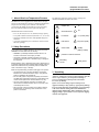
Installation and Operation Manual
Thermo Scientific Revco® PLUS HD
Ultra-Low Temperature Freezers
©
2009 Thermo Fisher Scientific. All rights reserved.
“Suva®” is a registered trademark of DuPont.
All other trademarks are the property of Thermo Fisher Scientific Inc. and its subsidiaries.
2007 Thermo Fisher Scientific. All rights reserved.
“Suva®” is a registered trademark of DuPont.
All other trademarks are the property of Thermo Fisher Scientific Inc. and
its subsidiaries.
Installation and Operation
Upright HD Series Freezers
Table of Contents
1 About Ultra-Low Temperature Freezers
2 Safety Precautions
3 Unpacking
................................................ 1
................................................................. 1
........................................................................ 1
4 General Recommendations
4.1 Temperature Monitoring
.......................................................... 2
. . . . . . . . . . . . . . . . . . . . . . . . . . . . . . . . . . . . . . . . . . . . . . . . . . . . . . . . . . . . . . . . . . . .2
4.2 General Usage
. . . . . . . . . . . . . . . . . . . . . . . . . . . . . . . . . . . . . . . . . . . . . . . . . . . . . . . . . . . . . . . . . . . . . . . . . . .2
4.3 Initial Loading
. . . . . . . . . . . . . . . . . . . . . . . . . . . . . . . . . . . . . . . . . . . . . . . . . . . . . . . . . . . . . . . . . . . . . . . . . . . .2
5 Operating Standards
6 Installation
............................................................... 2
........................................................................ 2
6.1 Location
6.2 Wiring
. . . . . . . . . . . . . . . . . . . . . . . . . . . . . . . . . . . . . . . . . . . . . . . . . . . . . . . . . . . . . . . . . . . . . . . . . . . . . . . .2
. . . . . . . . . . . . . . . . . . . . . . . . . . . . . . . . . . . . . . . . . . . . . . . . . . . . . . . . . . . . . . . . . . . . . . . . . . . . . . . . . .2
6.3 Leveling
. . . . . . . . . . . . . . . . . . . . . . . . . . . . . . . . . . . . . . . . . . . . . . . . . . . . . . . . . . . . . . . . . . . . . . . . . . . . . . . .3
6.4 High Density Cabinet Construction
6.5 Door Operation
. . . . . . . . . . . . . . . . . . . . . . . . . . . . . . . . . . . . . . . . . . . . . . . . . . . . . . . . . . . .3
. . . . . . . . . . . . . . . . . . . . . . . . . . . . . . . . . . . . . . . . . . . . . . . . . . . . . . . . . . . . . . . . . . . . . . . . . . .3
6.5.1
Opening the Door
. . . . . . . . . . . . . . . . . . . . . . . . . . . . . . . . . . . . . . . . . . . . . . . . . . . . . . . . . . . . . . . . . .3
6.5.2
Closing the Door
. . . . . . . . . . . . . . . . . . . . . . . . . . . . . . . . . . . . . . . . . . . . . . . . . . . . . . . . . . . . . . . . . . .3
6.6 Pressure Equalization Port
. . . . . . . . . . . . . . . . . . . . . . . . . . . . . . . . . . . . . . . . . . . . . . . . . . . . . . . . . . . . . . . . . .3
7 Remote Alarm and Analog Output (optional)
............................................ 4
7.1 Remote Alarm Contacts (optional)
. . . . . . . . . . . . . . . . . . . . . . . . . . . . . . . . . . . . . . . . . . . . . . . . . . . . . . . . . . . .4
7.2 4-20mA Analog Output (optional)
. . . . . . . . . . . . . . . . . . . . . . . . . . . . . . . . . . . . . . . . . . . . . . . . . . . . . . . . . . . . .4
8 Control Panel (Ultima Plus and Elite Plus models)
9 Start Up and Operation (Ultima Plus and Elite Plus)
9.1 Turning the Power On
9.2 Error Messages
...................................... 6
. . . . . . . . . . . . . . . . . . . . . . . . . . . . . . . . . . . . . . . . . . . . . . . . . . . . . . . . . . . . . . . . . . . . . .6
. . . . . . . . . . . . . . . . . . . . . . . . . . . . . . . . . . . . . . . . . . . . . . . . . . . . . . . . . . . . . . . . . . . . . . . . . .6
9.3 Setting the Cabinet Temperature
. . . . . . . . . . . . . . . . . . . . . . . . . . . . . . . . . . . . . . . . . . . . . . . . . . . . . . . . . . . . .6
9.4 Setting the Alarms (Ultima Plus and Elite Plus)
9.5 Recording Excursions and Resetting Alarms
9.5.1
Automatic Incident Monitor
9.5.2
Alarm Reset
9.6 Alarm Test
....................................... 5
. . . . . . . . . . . . . . . . . . . . . . . . . . . . . . . . . . . . . . . . . . . . . . . . . .6
. . . . . . . . . . . . . . . . . . . . . . . . . . . . . . . . . . . . . . . . . . . . . . . . . . . .7
. . . . . . . . . . . . . . . . . . . . . . . . . . . . . . . . . . . . . . . . . . . . . . . . . . . . . . . . . . .7
. . . . . . . . . . . . . . . . . . . . . . . . . . . . . . . . . . . . . . . . . . . . . . . . . . . . . . . . . . . . . . . . . . . . . . .7
. . . . . . . . . . . . . . . . . . . . . . . . . . . . . . . . . . . . . . . . . . . . . . . . . . . . . . . . . . . . . . . . . . . . . . . . . . . . . . .7
9.7 Program Mode
. . . . . . . . . . . . . . . . . . . . . . . . . . . . . . . . . . . . . . . . . . . . . . . . . . . . . . . . . . . . . . . . . . . . . . . . . . .8
i
Installation and Operation
Upright HD Series Freezers
10 Value Plus Models – Operation
10.1Value Plus Control Panel
10.2Turning the Power On
10.3Error Messages
....................................................... 9
. . . . . . . . . . . . . . . . . . . . . . . . . . . . . . . . . . . . . . . . . . . . . . . . . . . . . . . . . . . . . . . . . . .9
. . . . . . . . . . . . . . . . . . . . . . . . . . . . . . . . . . . . . . . . . . . . . . . . . . . . . . . . . . . . . . . . . . . . . .9
. . . . . . . . . . . . . . . . . . . . . . . . . . . . . . . . . . . . . . . . . . . . . . . . . . . . . . . . . . . . . . . . . . . . . . . . . .9
10.4Setting the Cabinet Temperature
10.5Alarm Operation
. . . . . . . . . . . . . . . . . . . . . . . . . . . . . . . . . . . . . . . . . . . . . . . . . . . . . . . . . . . .10
. . . . . . . . . . . . . . . . . . . . . . . . . . . . . . . . . . . . . . . . . . . . . . . . . . . . . . . . . . . . . . . . . . . . . . . . .10
10.5.1 Setting the Alarms
. . . . . . . . . . . . . . . . . . . . . . . . . . . . . . . . . . . . . . . . . . . . . . . . . . . . . . . . . . . . . . . . .10
10.5.2 Silencing the Alarms
. . . . . . . . . . . . . . . . . . . . . . . . . . . . . . . . . . . . . . . . . . . . . . . . . . . . . . . . . . . . . . .10
11 Backup System (Optional)
. . . . . . . . . . . . . . . . . . . . . . . . . . . . . . . . . . . . . . . . . . . . . . . . . . . . . . . . . . 10
11.1 CO2 and LN2 Precautions
. . . . . . . . . . . . . . . . . . . . . . . . . . . . . . . . . . . . . . . . . . . . . . . . . . . . . . . . . . . . . . . . .10
11.2 Installation
11.3 Startup
11.4 Operation
. . . . . . . . . . . . . . . . . . . . . . . . . . . . . . . . . . . . . . . . . . . . . . . . . . . . . . . . . . . . . . . . . . . . . . . . . . . . . .10
. . . . . . . . . . . . . . . . . . . . . . . . . . . . . . . . . . . . . . . . . . . . . . . . . . . . . . . . . . . . . . . . . . . . . . . . . . . . . . . .10
. . . . . . . . . . . . . . . . . . . . . . . . . . . . . . . . . . . . . . . . . . . . . . . . . . . . . . . . . . . . . . . . . . . . . . . . . . . . . . 11
11.5 System Status Lights
. . . . . . . . . . . . . . . . . . . . . . . . . . . . . . . . . . . . . . . . . . . . . . . . . . . . . . . . . . . . . . . . . . . . . 11
12 Maintenance and Troubleshooting
12.1Cleaning the Condenser
. . . . . . . . . . . . . . . . . . . . . . . . . . . . . . . . . . . . . . . . . . . . . . . . . . . . . . . . . . . . . . . . . . . 11
12.2Cleaning the Condenser Filter
12.3Gasket Maintenance
12.4Defrosting the Freezer
. . . . . . . . . . . . . . . . . . . . . . . . . . . . . . . . . . . . . . . . . . . . . . . . . . . .11
. . . . . . . . . . . . . . . . . . . . . . . . . . . . . . . . . . . . . . . . . . . . . . . . . . . . . . . . . . . . . . 11
. . . . . . . . . . . . . . . . . . . . . . . . . . . . . . . . . . . . . . . . . . . . . . . . . . . . . . . . . . . . . . . . . . . . . . 11
. . . . . . . . . . . . . . . . . . . . . . . . . . . . . . . . . . . . . . . . . . . . . . . . . . . . . . . . . . . . . . . . . . . . 11
12.5Alarm Battery Maintenance
. . . . . . . . . . . . . . . . . . . . . . . . . . . . . . . . . . . . . . . . . . . . . . . . . . . . . . . . . . . . . . . . 11
12.6Troubleshooting Procedures
. . . . . . . . . . . . . . . . . . . . . . . . . . . . . . . . . . . . . . . . . . . . . . . . . . . . . . . . . . . . . . . . 11
13 Chart Recorders
. . . . . . . . . . . . . . . . . . . . . . . . . . . . . . . . . . . . . . . . . . . . . . . . . . . . . . . . . . . . . . . . . . 12
13.1Set Up and Operation
. . . . . . . . . . . . . . . . . . . . . . . . . . . . . . . . . . . . . . . . . . . . . . . . . . . . . . . . . . . . . . . . . . . . .12
13.2Changing Chart Paper
. . . . . . . . . . . . . . . . . . . . . . . . . . . . . . . . . . . . . . . . . . . . . . . . . . . . . . . . . . . . . . . . . . . .12
13.3Calibration Adjustment
. . . . . . . . . . . . . . . . . . . . . . . . . . . . . . . . . . . . . . . . . . . . . . . . . . . . . . . . . . . . . . . . . . . .12
ii
Installation and Operation
Upright HD Series Freezers
1
About Ultra-Low Temperature Freezers
Plus HD Series -86ºC upright freezers feature the use of high
density vacuum insulation technology to minimize wall thickness
and provide extra storage space. Because of the thin wall
construction, HD models can hold 20 percent more inventory
than conventional models that take up the same lab space.
Standard HD Series features include:
•
•
•
•
25 cu. ft. (691 liter) or 32 cu. ft. (906 liter) storage capacity
Low profile cabinet construction (less than 77.5”, or 197 cm)
Separately mounted inner doors with adjustable hinges for
each door
A pressure equalization port to combat the vacuum created
after door openings
2 Safety Precautions
The following symbols are used in caution, warning and
informational labels attached to the freezer:
caution, info
on
electrical hazard
off
hot surface
on (control panel)
cold surface
off (control panel)
watch hands
standby
(battery enable)
In this manual and on labels attached to this product, the words
WARNING and CAUTION mean the following:
• WARNING: a potentially hazardous situation which, if not
avoided, could result in serious injury or death.
protective conductor terminal
• CAUTION: a potentially hazardous situation which, if not
avoided, may result in minor or moderate injury or damage to
the equipment.
Before installing, using or maintaining this product, please be sure
to read this manual and product warning labels carefully. Failure to
follow these instructions may cause this product to malfunction,
which could result in injury or damage.
alternating
current
earth ground
Below are important safety precautions that apply to this product:
• Use this product only in the way described in the product
literature and in this manual. Before using it, verify that this
product is suitable for its intended use.
• Do not modify system components, especially the controller.
Use OEM exact replacement equipment or parts. Before use,
confirm that the product has not been altered in any way.
• Your unit must be properly grounded in conformity with
national and local electrical codes. Never connect the unit to
overloaded power sources.
• Disconnect the unit from all power sources before cleaning,
troubleshooting, or performing other maintenance on the
product or its controls.
3 Unpacking
At delivery, examine the exterior for physical damage while the
carrier’s representative is present. If exterior damage is
present, carefully unpack and inspect the unit and all
accessories for damage.
If there is no exterior damage, unpack and inspect the
equipment within five days of delivery. If you find any damage,
keep the packing materials and immediately report the damage
to the carrier. Do not return goods to the manufacturer
without written authorization. When submitting a claim for
shipping damage, request that the carrier inspect the shipping
container and equipment.
1
Installation and Operation
Upright HD Series Freezers
4 General Recommendations
6 Installation
4.1 Temperature Monitoring
Do not exceed the electrical and temperature ratings printed on
the dataplate located on the lower left side of the unit.
IMPORTANT NOTE: We recommend the use of a redundant and
independent temperature monitoring system so that the
freezer can be monitored continuously for performance
commensurate with the value of product stored.
4.2 General Usage
The refrigeration system is designed to maintain ultra-low
temperatures with safety in an ambient environment up to +32°C
(90°F) , only when the freezer is used for storage.
WARNING! This unit is not a “rapid-freeze” device.
Freezing large quantities of liquid, or high-water
content items, will temporarily increase the chamber
temperature and will cause the compressors to
operate for a prolonged time period.
Avoid opening the door for extended time periods since chamber
temperature air will escape rapidly. Also, keep the inner doors
closed as much as possible. When room air, which is higher in
humidity, replaces chamber air, frost may develop in the chamber
more rapidly.
4.3 Initial Loading
After reading and completing the Safety Considerations,
Pre-Installation, Installation, and Operation sections of this
manual, start up the freezer following the instructions in
Section 9.1 on page 6.
Allow the freezer to operate at the desired temperature for a
minimum of 12 hours before loading.
Load the freezer one shelf at a time, beginning with the top shelf.
After loading each shelf, allow the freezer to recover to the
desired setpoint before loading the next shelf. Repeat this process
until the freezer is fully loaded.
CAUTION! Failure to follow these procedures or
overloading the unit may cause undue stress on the
compressors or jeopardize user product safety.
5 Operating Standards
The freezers described in this manual are classified for use as
stationary equipment in a Pollution Degree 2 and Overvoltage
Category II environment.
These units are designed to operate under the following
environmental conditions:
•
•
•
•
•
Indoor use
Altitude up to 2000m
Maximum relative humidity 60% for temperatures
up to 26ºC (80ºF)
Temperature range 16ºC (60ºF) to 32ºC (90ºF)
Main supply voltage fluctuations not to exceed 10% of the
nominal voltage.
CAUTION! Improper operation of the equipment
could result in dangerous conditions. To preclude
hazard and minimize risk, follow all instructions and
operate within the design limits noted on the
dataplate.
6.1 Location
Install the unit in a level area free from vibration with a minimum
of five inches of space on the top and back, eight inches on each
side. Refer to Section 6.3 for further instructions on leveling
cabinets. Allow enough clearance so that door can swing open at
least 90 degrees.
Do not position the equipment in direct sunlight or near heating
diffusers, radiators, or other sources of heat. The ambient
temperature range at the location must be 60 to 90°F
(16 to 32°C).
CAUTION! To allow for proper air flow, a minimum
of six inches of clearance space is required on the
sides, top and rear of the freezer.
6.2 Wiring
CAUTION! Connect the equipment to the correct
power source. Incorrect voltage can result in severe
damage to the equipment.
CAUTION! For personal safety and trouble-free
operation, this unit must be properly grounded before
it is used. Failure to ground the equipment may cause
personal injury or damage to the equipment. Always
conform to the National Electrical Code and local
codes. Do not connect the unit to overloaded power
lines.
CAUTION! Do not position the unit in a way that
impedes access to the disconnecting device or circuit
breaker in the back of the unit.
Always connect the freezer to a dedicated (separate) circuit. Each
freezer is equipped with a service cord and plug designed to
connect it to a power outlet which delivers the correct voltage.
Supply voltage must be within +10% or -10% of the freezer rated
voltage.
CAUTION! Never cut the grounding prong from the
service cord plug. If the prong is removed, the
warranty is invalidated.
2
Installation and Operation
Upright HD Series Freezers
6.3 Leveling
6.5.2 Closing the Door
Make sure that the floor is level. The unit must be level both
front to back and side to side.
Note that the latch does not self-engage automatically when you
close the door. You must rotate the latch into the open position
first.
6.4 High Density Cabinet Construction
In HD models, the cabinet walls have a vacuum insulation core
encapsulated by a sealed film laminate and wrapped in Mylar.
CAUTION! Never drill holes in or near the cabinet
walls. Drilling could damage the insulation and make
the unit inoperable.
6.5 Door Operation
Upright freezer models are equipped with an advanced
Cryolatch™ assembly specifically designed for ultra-low
temperature freezers.
Features include:
• One-hand operation
• A front-accessible lock, keyed to match the freezer control
lock
• Hasps for a standard padlock to provide additional security
• Durable construction for reliable operation and safe product
storage.
CAUTION! When moving the freezer, always grasp
cabinet surfaces; never pull the freezer by the latch
handle.
6.5.1 Opening the Door
1. Remove the padlock if you have one.
2. Move the key into the open position by rotating it counterclockwise.
3. Grasp the latch handle (preferably with your left hand) and
pull it toward yourself until the latch disengages from the
cabinet strike.
4. Keep pulling by the latch handle or the integrated door
handle to open the main door.
1. Grasp the latch handle (preferably with your left hand) and
pull it toward yourself, rotating the latch into the open
position.
2. Move the freezer door into the closed position and gently
push the handle away from you, making sure that the latch
engages fully with the cabinet strike.
CAUTION! Closing the door without making sure
the latch engages fully with the strike can result in
substantial prying forces on the door.
3. Keep applying gentle pressure to the latch handle until the
latch is securely in closed position.
4. Insert the key and rotate clockwise to lock.
5. Replace the padlock if you are using one.
6.6 Pressure Equalization Port
When an upright ultra-low temperature freezer door is opened,
room temperature air rushes into the storage compartment.
When the door is closed, the fixed volume of air is cooled rapidly.
Pressure drops below atmospheric pressure, resulting in a
substantial vacuum. Re-entry into the cabinet is impossible until
internal pressures are returned to atmospheric pressure. Without a
pressure equalization mechanism, it can take, in extreme cases,
several hours before the door can easily be reopened.
All upright models feature a port that provides vacuum relief
after door openings.
The pressure equalization port is located in the door behind the
eye-level panel on the front of the freezer. Although the port is
designed to self-defrost, excessive frost accumulation on the
inner door could eventually restrict air flow. Therefore you
should periodically inspect the inner door and brush away any
loose frost using a stiff nylon brush.
3
Installation and Operation
Upright HD Series Freezers
7 Remote Alarm and Analog Output
Skip the following installation procedures if you are not using the remote alarm and/or analog output options.
7.1 Remote Alarm Contacts (optional)
If you are using a remote alarm system, you need to install the remote alarm connector provided with your freezer.
The remote alarm contacts are located on the back of the freezer above and to the left of the power switch. After installing the wiring
from the remote alarm to the connector, install the connector to the freezer microboard.
When the unit is in the alarm condition:
•
•
•
The leftmost pin (#7) is NO (normally open) output.
The second pin from the left (#6) is COM (common).
The third pin from the left (#5) is NC (normally closed).
The contacts will trip in the event of a power outage, high temperature alarm or low temperature alarm.
7.2 4-20mA Analog Output (optional)
The analog output function allows the freezer to output a current signal proportional to the temperature of the freezer cabinet. The
output is factory configured as a 4-20mA self powered current loop. The output driver circuitry is optimized for a load of 250 ohms.
The passive monitoring device is connected to pins 1 and 2 of the Remote Alarm Contacts and Analog Output connector.
CAUTION!
The passive monitoring device must not provide power to the loop, otherwise damage will occur.
4
Installation and Operation
Upright HD Series Freezers
8 Control Panel
2
10 11
12
19
20
21
BACKUP SYSTEM
SUPPLY
ON
CABINET
TEMPERATURE
LIFE-GUARD ALERT
OFF
POWER ON
SET POINT SECURITY
TEMPERATURE FAILURE
ALARM TEST
ALARM RESET
BATTERY
LOW
EXTREME AMBIENT ALERT
CONTROL
SET POINT
POWER FAILURE
ALARM ON
SUPPLY
EMPTY
CLEAN FILTER
WARM ALARM
SET POINT
ALARM
BATTERY LOW
COLD ALARM
SET POINT
VOLTAGE
15
16
1
22
6
7
3
4
Figure 1. Ultima Plus Series Control Panel with
Optional Backup System
Before the initial start up, take some time to become familiar
with the controls on your freezer. Figure 1 illustrates the Ultima
Plus upright freezer control panel.
1. Three position keyed Power On Switch.
2. Power On Indicator. This green LED lights when power is
connected to the freezer and the key switch is in the ON
position.
3. Temperature Failure Indicator. This indicator lights when the
freezer temperature deviates either above or below the alarm
temperature settings.
4. Power Failure Indicator. This indicator lights when there is a
power failure to the freezer.
5. Life-Guard Alert Indicator. This indicator lights when the
first stage compressor has gone into a cautionary state of
operation to help prevent failure.
6. Alarm Test Pad. Press this pad to start an alarm test (refer to
Section 8.5 on page 6).
7. Alarm Reset Pad. Press this pad to reset slowly blinking
indicators. Slowly blinking indicators denote that the
condition has occurred but is now within the given operating
parameters. This pad is also depressed to temporarily silence
the audible alarm.
8. Cold Alarm Setpoint. Press this pad to display the cold alarm
setpoint (refer to Section 9.4 on page 6).
9. Warm Alarm Setpoint. Press this pad to display the warm
alarm setpoint (refer to Section 9.4 on page 6).
10. Control Setpoint. Press this pad to set the cabinet temperature
(refer to Section 9.3 on page 6).
11. Cabinet Temperature Indicator. Displays cabinet temperature
in operating mode, parameters and values when in program
mode (refer to Section 9.7 on page 8).
12. Digital Temperature Display Window. This window displays
chamber temperature, alarm values, etc. depending on the
operating status of the freezer and the procedure being
performed.
5
8
9
13 14
18 17
13. Decrement Pad ( ). Use this pad to decrease temperature
values.
14. Increment Pad ( ). Use this pad to increase temperature
values.
15. Extreme Ambient Alert. This indicator lights when the
ambient temperature has exceeded the upper limit of the
recommended operating range. If the Extreme Ambient Alert
is activated, the ambient environment needs to be improved
for proper function of the freezer.
16. Clean Filter Indicator. This indicator lights when the air
cooled condenser filter is dirty.
17. Alarm Battery Low Indicator. This indicator lights when the
charge on the alarm battery is low. Press this button to
display the battery charge (in volts) in the digital display
window.
18. Voltage Indicator. Press this pad to display the current line
voltage in the digital display window. A built-in power
management system boosts voltage when it is low and lowers
voltage when it is high.
22. Alarm On/Set Point Security Indicator. This indicator lights
when the alarm is activated.Also indicates that Setpoint
Security is activated .
The following indicators are available only when the freezer is
equipped with the optional backup system (refer to Section 10.5
on page 9).
19. Backup System Supply On Indicator.
20. Backup System Empty Indicator
21. Backup System Battery Low Indicator.
5
Installation and Operation
Upright HD Series Freezers
9 Start Up and Operation
Refer to Figure 1 on page 5 as you complete the following
procedures.
9.1 Turning the Power On
To start up your freezer, complete the following steps:
1. Plug the freezer into the power outlet.
2. If you do not have the CO2/LN2 backup option installed,
remove the panel near the lower left corner of the front of the
freezer and turn on the Battery Enable switch. Replace the
panel.
3. If you do have the CO2/LN2 backup option installed, wait
until the freezer has pulled down to operating setpoint before
turning on the Battery Enable switch. Refer to Section 10 on
page 9 for backup system installation and operation
instructions.
4. Turn the power switch in back of the freezer, on the bottom
right, to the ON position.
The Low Battery indicator may flash during startup, indicating
that the battery is recharging.
Note:
The alarm function is not active at this time. Refer to
Section 9.4 for information about setting the alarms. In
addition, the Setpoint Security will be deactivated in this
key position.
9.2 Error Messages
If at any time during startup and operation, an error message
appears in the main display, be sure to call Technical Service
immediately.
Error messages are of the form “ErXX”. ErX1 indicates incorrect
voltage or frequency, and ErX2 through ErX4 indicate sensor
failure.
9.3 Setting the Cabinet Temperature
To set the cabinet temperature, complete the following steps:
1. Press and hold the Control Setpoint pad.
2. The Control setpoint LED lights and the Cabinet
Temperature LED goes out.
3. Press and hold
to increase the temperature or
to
decrease the temperature. The digital display scrolls through
temperature settings.
4. Release both pads when the digital temperature display
window shows the correct setpoint value.
Note: If no keys are pressed within two seconds, the
temperature display reverts to the cabinet temperature.
9.4 Setting the Alarms
On Ultima Plus models, the warm and cold alarms may be set
following the instructions below.
To set the cold alarm, complete the following steps:
1. Confirm that the key switch is at the Power On (not the
Alarm On) position.
2. Press and hold the Cold Alarm Setpoint pad. The LED next
to this pad lights. The temperature display shows the Cold
Alarm value.
3. Press and hold
or
to adjust the Cold Alarm Setpoint,
which must be 5ºC colder than the operating setpoint. When
the cabinet temperature setpoint is changed, the alarm
setpoints are adjusted automatically to maintain a constant
difference.
4. Release both pads when the digital temperature display
window shows the correct setpoint value.
To set the warm alarm, complete the following steps:
1. Confirm that the key switch is at the Power On (not the
Alarm On) position.
2. Press and hold the Warm Alarm Setpoint pad. The LED next
to this pad lights. The temperature display shows the Warm
Alarm value.
3. Press and hold
or
to adjust the Warm Alarm Setpoint,
which must be 5ºC warmer than the cabinet temperature
setpoint. When the cabinet temperature setpoint is changed,
the alarm setpoints are adjusted automatically to maintain a
5ºC difference.
4. Release both pads when the digital temperature display
window shows the correct setpoint value.
When the cabinet temperature drops below the Warm Alarm
setting, turn the key switch to ALARM ON. The freezer is ready
to operate.
Note:
If a power failure occurs, the POWER ON light goes out,
the POWER FAILURE light and digital temperature
display flash simultaneously, and a buzzer sounds if it
has not been muted.
CAUTION! You must turn the three-position key
switch to the ALARM ON/SETPOINT SECURITY
position to activate the audible alarm and place it in
security operation. Remote alarm contacts will work in
either ON position.
6
Installation and Operation
Upright HD Series Freezers
9.5 Recording Excursions and Resetting Alarms
9.6 Alarm Test
9.5.1 Automatic Incident Monitor
To test the warm alarm, turn the key switch to the ALARM ON
position and complete the following steps:
The Automatic Incident Monitor records excursions, that is
extreme warm and cold temperature values.
You can view excursions by simultaneously pressing the Cabinet
Temperature and Warm Alarm Setpoint pads for high excursion,
and the Cabinet Temperature and Cold Alarm Setpoint pads for
low excursion.
IMPORTANT NOTE: When alarms are activated because of
temperature failure, it is advisable to view and record
excursions (extreme high and low temperatures) before
resetting the alarms. Alarm reset has the effect of
resetting excursion values to the current cabinet
temperature.
1. Press and hold the Alarm Test pad. The digital temperature
display indicates rising temperature. When the temperature
reaches the warm alarm value, the audible and visual alarms
alarms will be activated, as well as remote alarms, but
excursions (extreme temperatures) will not be logged.
Note:
The temperature of the refrigerated space does not
change during this procedure.
2. Release the Alarm Test pad. The display returns to cabinet
temperature.
9.5.2 Alarm Reset
The alarm reset feature, activated by pressing the Alarm Reset
pad, ensures user acknowledgment of the occurrence of certain
alarm conditions. This provides greater monitoring power by
alerting the user if an alarm condition has occurred during
periods when the freezer must be left unattended.
The alarm conditions that can be reset are:
•
•
•
•
•
•
Temperature Failure-Warm Alarm
Temperature Failure-Cold Alarm
Power Failure
Extreme Ambient Alert
Life Guard Alert
Clean Filter
During any of these alarm conditions, the corresponding
indicator will flash quickly. If the alarm condition then
disappears, the flash rate will decrease. The indicator will then
remain flashing at this rate, unless the condition reoccurs, until
the Alarm Reset button is pressed. Once the Alarm Reset button
has been pressed, the indicator will no longer be lit.
The alarm reset function also resets the battery alarm but does
not affect the status of remote alarms.
In the case of Temperature Failure-Warm Alarm And
Temperature Failure-Cold Alarm, if these conditions have
occurred but are now within the given limits, the two indicators
will alternately flash (180° out of phase).
Once the Alarm Reset button is pressed, the extreme temperature
value is reset to the current cabinet temperature.
7
Installation and Operation
Upright HD Series Freezers
9.7
Program Mode
You can use Program Mode to display and adjust various parameters.
CAUTION! Do not change the values of Program Mode parameters without consulting Technical Service. Shutdown and/or
damage to the freezer could result from improper setting of parameters.
To enter Program Mode, press the Cabinet Temperature pad and hold for 5 seconds. “Prg” will be displayed until you release the pad.
In Program Mode, parameter labels and values are displayed instead of cabinet temperature. The display advances to the next item after
a 1.5 second timeout, or when you press the Cabinet Temperature pad.
After 10 seconds of inactivity at any point in the session, Program Mode is deactivated and the cabinet temperature is displayed again.
Table 1.
Program Mode Parameters
Parameter
Display
Notes
Revision
Displays micro firmware revision in
MMmm format.
Display only: “Er06” error if firmware integrity test fails.
Offset
“oFF” then “SEt”, followed by offset
value.
Offset for calibration: do not adjust without consulting
Technical Service. Adjustable using
and . Default
value is 0; range is -10ºC to 7ºC.
Value displayed in minutes, in steps of one tenth of a minute.
Default is 0.0; range is 0.0 to 20.0. Adjustable using
and
Time Delay
“tI” then “dLy”, followed by value.
This feature may be used to stagger restart times in case
you have multiple freezers.
BUS Type
Displays backup system type only
when a backup system is detected.
Display only. Use
and
to toggle between the values
“Ln2” and “co2”. Changing this value automatically changes
the default setpoint.
BUS Setpoint
Setpoint value in display (only when a
backup system is detected).
Adjustable using
and
range is -0ºC to -65ºC;
. LN2 range is -0ºC to -76ºC; C02
Lifeguard
Displays Lifeguard value.
Adjustable using
70ºC to 98ºC.
. Default value is 94ºC; range is
and
8
Installation and Operation
Upright HD Series Freezers
10 Backup System (Optional)
•
•
When you purchase a built-in CO2 or LN2 optional backup
system for the freezer, backup control is integrated into Program
Mode (described in Section 9.7 on page 8).
Note:
Always purchase the cylinders which are equipped with
siphon tubes for withdrawing liquid from the bottom of
the cylinder. CO2 cylinders must be kept at room
temperature to function properly. LN2 bottles are
functional at any reasonable temperature.
10.1 CO2 and LN2 Precautions
The following are precautions for using liquid CO2 and LN2
backup systems.
WARNING! If a CO2 or LN2 cylinder falls and a
valve is knocked off, the cylinder becomes a deadly
and completely unguided missile. Transport the
cylinders in a handtruck or cart with secure chain ties
for the cylinder. After cylinders are connected to the
equipment, securely attach them with chains to a
solid, stationary object such as a building column.
WARNING! CO2 and LN2 liquids are non-poisonous
but are very cold and will burn unprotected skin.
Always wear protective eyewear and clothing when
changing cylinders or working on the piping systems
attached to an active source of liquid refrigerant.
WARNING! The gases produced by evaporation of
CO2 or LN2 are non-poisonous but displace the
oxygen in a confined space and can cause
asphyxiation. Do not store the cylinders in subsurface
or enclosed areas.
CAUTION! When closing the cylinder valve, make
sure that the injection solenoid is energized to allow
all the liquid to bleed off instead of being trapped in
the supply tubing. Failure to do this results in
activation of the pressure relief device, which could
damage the freezer and requires replacing if it is
activated.
CAUTION! For models ordered with factory
installed built-in backup systems, the flow of liquid
CO2 or LN2 will be discontinued if the door is opened
during operation of the backup system. For units
operated with free-standing, field installed type
backup system, the flow of liquid CO2 or LN2 will be
discontinued upon door opening only if the switch
provided with the free-standing package is installed on
the freezer.
10.2 Installation
Field installed systems are supplied with complete installation
and operating instructions. If your system is factory installed, the
freezer is shipped with a coiled length of tubing to connect the
freezer to the bottles:
3/8 in. OD copper tubing for connection to the CO2 supply.
5/8 in. OD copper tubing covered with Armaflex™ insulating
tubing for connection to the LN2 supply.
Straighten the coiled tubing and connect one end to the labeled
connection on the freezer and the other end to the supply bottle or
building supply fitting.
10.3 Startup
To activate the backup system;
1. Follow the instructions in Section 9 to power on the freezer
and set temperature and alarm setpoints.
2. Enter program mode and check the BUS setpoint value,
following the instructions in Section 9.7 on page 8. Adjust
this value if necessary.
3. Wait until the cabinet temperature has pulled down to below
the BUS setpoint value. This is important, because if you
turn on the Battery Enable Switch (Step 4) while the cabinet
is still warm, you may drain the battery.
4. When the freezer cabinet temperature is below the BUS
setpoint, activate the backup system by turning on the Battery
Enable Switch:
– Remove the panel near the lower left corner of the front of
the freezer.
– Turn on the Battery Enable Switch. Both the power switch
and the battery switch must be on for the backup system to
operate.
– Replace the panel.
5. Turn on the CO2 or LN2 supply.
10.4 Operation
When the backup system is in operation, you can view and reset
parameters in Program Mode (refer to Section 9.7 on page 8).
The backup system can run for a minimum of eight hours on
battery power.
10.5 System Status Lights
The built-in backup system includes main control panel system
status lights, which appear to the right of the main temperature
display as shown in Figure 1 on page 5.
•
•
The Supply On Indicator lights when the backup system is
operating on battery power and the system is actively
injecting CO2 or LN2.
The Backup System Battery Low Indicator lights when the
backup system battery charge is low. The built-in battery
charger recharges the battery to full charge when power is
restored to the system. Pressing Battery Low displays the
battery charge in tenths of a volt, then returns to the main
display after about one second.
Note:
Since rechargeable batteries degrade over time, the
battery should be replaced after approximately three
years or after an event which has required the injection
of CO2 or LN2.
9
Installation and Operation
Upright HD Series Freezers
•
The Backup System Empty Indicator lights when the standby
CO2 or LN2 bottle is empty.
11 Maintenance and Troubleshooting
Unauthorized repair of your freezer will invalidate your
warranty. Contact Technical Service at 1-800-438-4851 for
additional information.
CAUTION! Maintenance should only be performed
by trained personnel.
11.1 Cleaning the Condenser
Clean the condenser at least every six months; more often if the
laboratory area is extremely dust prone.
To clean the condenser, complete the following steps:
1. Pull the grill open.
2. Remove the filter. Check the fans. If a fan is not operating,
contact an authorized service company immediately.
3. Vacuum the condenser.
4. Replace the filter and close the grill.
11.2 Cleaning the Condenser Filter
Clean the condenser filter every two or three months.
1. Pull the grill open.
2. Remove the filter.
3. Shake the filter to remove loose dust, rinse the filter in clean
water, shake the excess water from the filter, and replace the
filter.
4. Close the grill.
11.3 Gasket Maintenance
Periodically check the gaskets around the door for punctures or
tears. Leaks are indicated by a streak of frost which forms at the
point of gasket failure. Make sure that the cabinet is level (refer
to Section 6.3 on page 3 for leveling information).
Keep the door gaskets clean and frost free by wiping gently with
a soft cloth.
11.4 Defrosting the Freezer
Defrost the freezer once or year or whenever the ice buildup
exceeds 3/8”.
To defrost, complete the following steps:
1. Remove all products and place in another cabinet.
2. Turn off the freezer.
3. Open the outer door and all inner doors.
4. Let the freezer stand with doors open for at least 24 hours.
This allows both the interior and foamed refrigerant system
to warm to room temperature.
5. Dispose of the ice and wipe out any water standing in the
bottom of the cabinet.
6. If there is freezer odor, wash the interior with a solution of
baking soda and warm water. Clean the exterior with any
common household cleaning wax.
7. Close the doors, restart the freezer and reload, following the
instructions in Section 4.3 on page 2.
11.5 Alarm Battery Maintenance
Have a certified technician replace the alarm battery after each
use, and check the condition of the battery at least once a year.
11.6 Troubleshooting Procedures
Table 2.
Troubleshooting Procedures
Problem
Solution
Clean Filter
indicator is on.
Condenser filter is dirty. Refer to Section 11.2.
Alarm Battery Low
indicator is on.
Alarm battery is low on charge. Have a
technician check the alarm battery. Refer to
Section 11.5.
10
Installation and Operation
Upright HD Series Freezers
12 Chart Recorders
CHANGE CHART
Panel-mounted six-inch seven-day recorders are available as
options for all freezer models.
3
12.1 Set Up and Operation
1
To prepare the recorder to function properly, complete the
following steps:
1. Open the recorder door to access the recorder.
2. Install clean chart paper (refer to Section 12.2 below).
3. Remove the plastic cap from the pen stylus and close the
recorder door.
Recorder operation begins when the system is powered on.The
recorder may not respond until the system reaches temperatures
within the recorder’s range.
2
Figure 3. Chart Buttons
CAUTION! Do not use sharp or pointed objects to
depress the chart buttons. This may cause permanent
damage to the recorder.
12.2 Changing Chart Paper
To change the chart paper, complete the following steps:
Chart Buttons
Imprinting
Stylus
Reference
Mark
Chart
Hub-Nut and
Retaining Wire
Figure 2. Chart Recorder
1. Locate the pressure sensitive buttons at the front, upper left
of the recorder panel.
2. Press and hold the Change Chart button (#3) for one second.
The pen will move off the scale.
3. Unscrew the center nut, remove the old chart paper, and
install new chart paper. Carefully align the day and time with
the reference mark (a small groove on the left side of the
recorder panel).
4. Replace the center nut and hand tighten. Press the Change
Chart button again to resume temperature recording.
12.3 Calibration Adjustment
This recorder has been accurately calibrated at the factory and
retains calibration even during power interruptions. If required,
however, adjustments can be made as follows:
1. Run the unit continuously at the control setpoint temperature.
Continue steady operation for at least two hours to provide
adequate time for recorder response.
2. Measure cabinet center temperature with a calibrated
temperature monitor.
3. Compare the recorder temperature to the measured cabinet
temperature. If necessary, adjust recorder by pressing the left
(#1) and right (#2) chart buttons.
Note:
The stylus does not begin to move until the button is held
for five seconds.
11
Thermo Scientific Revco PLUS Upright Freezers
Installation and Operation
WEEE Compliance
WEEE Compliance. This product is required to comply with the European
Union’s Waste Electrical & Electronic Equipment (WEEE) Directive 2002/96EC.
It is marked with the following symbol. Thermo Fisher Scientific has contracted
with one or more recycling/disposal companies in each EU Member State, and this
product should be disposed of or recycled through them. Further information on
Thermo Fisher Scientific compliance with these Directives, the recyclers in your
country, and information on Thermo Scientific products which may assist the
detection of substances subject to the RoHS Directive are available at
www.thermo.com/
Great Britain
WEEE Konformittät. Dieses Produkt muss die EU Waste Electrical & Electronic Deutschland
Equipment (WEEE) Richtlinie 2002/96EC erfüllen. Das Produkt ist durch
folgendes Symbol gekennzeichnet. Thermo Fisher Scientific hat Vereinbarungen
getroffen mit Verwertungs/Entsorgungsanlagen in allen EU-Mitgliederstaaten und
dieses Produkt muss durch diese Firmen widerverwetet oder entsorgt werden.
Mehr Informationen über die Einhaltung dieser Anweisungen durch Thermo
Fisher Scientific, die Verwerter und Hinweise die Ihnen nützlich sein können, die
Thermo Scientific Produkte zu identifizieren, die unter diese RoHS.
Anweisungfallen, finden Sie unter www.thermo.com/
Conformità WEEE. Questo prodotto deve rispondere alla direttiva dell’ Unione
Europea 2002/96EC in merito ai Rifiuti degli Apparecchi Elettrici ed Elettronici
(WEEE). È marcato col seguente simbolo.Thermo Fisher Scientific ha stipulato
contratti con una o diverse società di riciclaggio/smaltimento in ognuno degli Stati
Membri Europei. Questo prodotto verrà smaltito o riciclato tramite queste
medesime. Ulteriori informazioni sulla conformità di Thermo Fisher Scientific con
queste Direttive, l’elenco delle ditte di riciclaggio nel Vostro paese e informazioni
sui prodotti Thermo Scientific che possono essere utili alla rilevazione di sostanze
soggette alla Direttiva RoHS sono disponibili sul sito www.thermo.com/
Conformité WEEE. Ce produit doit être conforme à la directive européenne
(2002/96EC) des Déchets d’Equipements Electriques et Electroniques (DEEE). Il
est marqué par le symbole suivant. Thermo Fisher Scientific s’est associé avec une
ou plusieurs compagnies de recyclage dans chaque état membre de l’union
européenne et ce produit devraitêtre collecté ou recyclé par celles-ci. Davantage
d’informations sur laconformité de Thermo Fisher Scientific à ces directives, les
recycleurs dans votre pays et les informations sur les produits Thermo Scientific
qui peuvent aider le détection des substances sujettes à la directive RoHS sont
disponibles sur www.thermo.com/
Italia
France
12
Important
For your future reference and when contacting the factory, please have the
following information readily available:
Model Number:
Serial Number:
Date Purchased:
The above information can be found on the dataplate attached to the
equipment. If available, please provide the date purchased, the source of
purchase (the manufacturer or specific agent/rep organization), and purchase
order number.
IF YOU NEED ASSISTANCE:
SALES DIVISION
Phone:
828/658-2711
800/252-7100
Fax:
828/645-3368
LABORATORY PARTS and SERVICE
Phone:
800/438-4851
Fax:
828/658-2576
TECHNICAL SUPPORT
Phone:
800/438-4851
Thermo Fisher Scientific Inc.
275 Aiken Road
Asheville, NC 28804
United States
www.thermofisher.com
314099H01