1
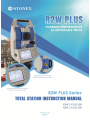
R2W PLUS
Dear Customer:
Congratulations! We, STONEX are proud to present you with an R2W PLUS
instrument. Your total station is a rugged and reliable instrument whose
performance and design are not surpassed.
To fully appreciate and protect your investment, we suggest that you take the
necessary time to read and fully understand this manual. We have a dedicated
service organization. If the need arises, please don’t hesitate to call us.
Thank you for your trust and confidence.
1
R2W PLUS
NOTE:
Don’t collimate the sun directly
Avoid insolating the instrument, and don’t collimate the sun directly for protecting eyes
and instrument.
Set up the instrument on the tripod
When using it please insure the connection between tripod and instrument is firm. It is
better to work with wooden tripod for the measurement accuracy.
Assemble the tribrach on the instrument
The setting of tribrach would influence the accuracy. The tribrach should be check
frequently, the screw which connects the tribrach and alidade must be locked tightly. And
the central fixing screw should be tight.
Avoiding the librations on the instrument
When transporting, keep the instrument in the case and try your best to lighten librations.
Carry the instrument
When carrying, the instrument handle must be held tight.
High temperature condition
If put the instrument in high temperature condition for a long time, it is bad for the
instrument performance.
Temperature changing sharply
The sharp temperature changing on the instrument or prism will shorten the distance
measurement range, for example, after taking the instrument out from a warm car to a
cold condition, wait for some time, it can be used when it adapts to the surrounding
condition.
Check the battery power
Before using it, you should check the power whether it is enough.
Take out the battery
It is not suggested to take out the battery when the instrument is on, otherwise, the stored
data may be lost, so it is better to replace the battery after power off the instrument.
Stored data responsibility
STONEX should not be held liability for the lost data because of wrong operation.
The noise from the instrument
When the instrument is working, it is normal if you hear the noise from instrument motor,
it will not affect the instrument work.
2
R2W PLUS
Definition of Indication
For the safety of your product and prevention of injury to operators and other persons as
well as prevention of property damage, items which should be observed are indicated by
an exclamation point within a triangle used with WARNING and CAUTION statements
in this manual.
The definitions of the indication are listed below. Be sure you understand them before
reading the manual’s main text.
!
WARNING:
Ignoring this indication and making an operation
error could possibly result in death or serious
injury to the operator.
!
Ignoring this indication and making an operation
CAUTION:
error could possibly result in personal injury or
property damage.
PRECAUTIONS FOR SAFE OPERATION
! WARNING
●Only STONEX authorized distributors can disassemble or rebuilt the instrument.
●Do not collimate the sun directly. The eye injury or blind could result.
●Cover the charger maybe result fire when charging.
●If use defection power cable, socket or plug, there is danger of fire, or electronic shock.
●Using wet battery or charger maybe result fire, or electronic shock.
●Do not close the instrument to burning gas or liquid, and do not use the instrument in
coal mine. Blast could be result.
●Do not put the battery in the fire or high temperature condition. Explosion, damage
could result.
●If use the battery which is not specified by STONEX, there is a danger of fire, electric
shock or burn.
●If use the power cable which is not specified by STONEX, there is a danger of fire.
●If short circuit of the battery, there is a danger of fire.
● When this product encounters disturbance of severe Electrostatic Discharge, perhaps it
will have some degradation of performance like switching on/off automatically and so on.
3
R2W PLUS
!
CAUTION
●If touch the instrument with wet hand, there is danger of electric shock.
●Stand or seat on the carrying case, or turn over the carrying case arbitrarily, the
instrument maybe damaged.
●Be careful of the tripod tiptoe when setup or move it.
●Drop the instrument or the carrying case, or use defective belt, agraffe or hinge,
instrument damage could result.
●Do not touch liquid leaking from the instrument or battery. Harmful chemicals could
cause burn or blisters.
●Please assemble the tribrach carefully, if the tribrach is not stable, series damage could
result.
●Drop the instrument or tripod, series damage could result. Before use it, check the
central screw is tight.
User
1) This product is for professional user only!
The user is required to be a qualified surveyor or have a good knowledge of surveying, in
order to understand the user manual and safety instructions, before operating, inspecting
or adjusting.
2) Wear the required protectors (safety shoes, helmet, etc.) when operating.
Exceptions from Responsibility
1) The user of this product is expected to follow all operating instructions and make
periodic checks of the product’s performance.
2) The manufacturer assumes no responsibility for results of a faulty or intentional usage
or misuse including any direct, indirect, consequential damage, and loss of profits.
3) The manufacturer assumes no responsibility for consequential damage, and loss of
profits by any disaster, (an earthquake, storms, floods etc.).
4) The manufacturer assumes no responsibility for any damage, and loss of profits due to
a change of data, loss of data, an interruption of business etc., caused by using the product
or an unusable product.
5) The manufacturer assumes no responsibility for any damage, and loss of profits caused
by usage except for explained in the user manual.
6) The manufacturer assumes no responsibility for damage caused by wrong transport, or
action due to connecting with other products.
4
R2W PLUS
Safety Standards for Laser (R2W PLUS Series)
R2W PLUS Series adopts the safe and visible laser on the basis of “Specification
Standard of radiant products” (FDA CDRH.21CFR Part 1040.10 and 1040.11) and
“Safety of laser products – parts 1: Equipment classification, requirements and user’s
guide” (IEC 60825-1:2001).
According to above standards, R2W PLUS Series is class ⅢA/3R laser products. When
the prism or reflective sheet is selected in Config mode as target, the output is equivalent
to the safer class 1.
Once the instrument is damaged, do not disassemble it. You’d better contact STONEX
or local dealer.
Labels
Follow the safety instructions on the labels as well as in this manual to ensure safe use .
Laser emit
Note for Safety
! WARNING
● Never point the laser beam at other’s eyes, it could cause serious injury.
● Never look directly into the laser beam source, it could cause permanent eye damage.
● Never stare at the laser beam, it could cause permanent eye damage.
● Never look at the laser beam through a telescope or other optical devices, it could cause
permanent eye damage.
5
R2W PLUS
CONTENT
NOTE: ................................................................................................................................ 2
Definition of Indication ..................................................................................................... 3
PRECAUTIONS FOR SAFE OPERATION .................................................................. 3
User ..................................................................................................................................... 4
Exceptions from Responsibility ........................................................................................ 4
1. Nomenclature and Functions ........................................................................................... 1
1.1 Nomenclature ........................................................................................................ 1
1.3 Comprehensive Understanding ............................................................................. 4
1.3.1 Basic Measurement .................................................................................... 4
1.3.2 Standard Measurement ............................................................................... 5
1.3.3 Instrument Setup......................................................................................... 5
1.3.4 About .......................................................................................................... 6
1.3.5 Third-party software ................................................................................... 6
1.3.6 Convenient panel ........................................................................................ 6
1.4 Shortcut key........................................................................................................... 7
1.5 Touch screen calibration ........................................................................................ 8
1.6 Battery ................................................................................................................... 9
1.6.1 Battery Power indicator .............................................................................. 9
1.6.2 Replace and mount battery ......................................................................... 9
1.6.3 Recharge battery ....................................................................................... 10
1.7 USB connection................................................................................................... 11
1.8 Guide light (Optional) ......................................................................................... 12
2. Preparation before Measurement................................................................................... 13
2.1 Setting up the instrument..................................................................................... 13
2.2 Levelling-Up ....................................................................................................... 13
2.3 Centering ............................................................................................................. 15
2.3.1 Centering with Optical Plummet (Optional) ............................................ 15
2.3.2 Centering with Laser Plummet ................................................................. 16
3 Instrument settings ......................................................................................................... 17
3.1 INST Setup .......................................................................................................... 17
3.1.1 Setting the measure condition .................................................................. 18
3.1.2 Setting the units ........................................................................................ 18
3.1.3 Setting parameters of communication ports ............................................. 19
3.1.4 Instrument parameters review .................................................................. 19
3.2 Illumination settings ............................................................................................ 20
1
R2W PLUS
4. Basic measurement program ......................................................................................... 21
4.1 Run the program “Basic Measurement” .............................................................. 21
4.2 Basic measurement screen introduction .............................................................. 21
4.3 Angle measurement mode ................................................................................... 22
4.3.1 Horizontal angle(right angle) and vertical angle measurements .............. 22
4.3.2 Horizontal angle switch between right and left ........................................ 23
4.3.3 Setting horizontal angle with the “L.Angle” key ..................................... 24
4.3.4 Setting horizontal angle with the “S.Angle” key ...................................... 25
4.3.5 Setting “vertical angle and percent grade” mode with the “V/%” key ..... 26
4.3.6 Carrying out angle retesting with the “Repeat” key ................................. 27
4.4 Distance measurement mode ............................................................................... 30
4.4.1 Distance measurement and measuring mode setting ................................ 30
4.4.2 Fine/Tracking distance measurement ....................................................... 31
4.4.3 Accurate Measurement and Track mode .................................................. 33
4.4.4 Exchange of distance units ....................................................................... 34
4.4.5 Distance stake out measurement .............................................................. 34
4.4.6 Remote Elevation Measurement (REM) .................................................. 36
4.4.7 Missing Line Measurement (MLM) ......................................................... 41
4.4.8 Line-height Measurement......................................................................... 44
4.5 Coordinate Measurement Mode .......................................................................... 49
4.5.1 Setting coordinate of occupied point ........................................................ 49
4.5.2 Setting backsight point ............................................................................. 50
4.5.3 Setting instrument height and prism height .............................................. 52
4.5.4 Operation of coordinate measurement...................................................... 53
4.5.5 Traverse Surveying ................................................................................... 54
4.5.6 Offset Measurement Mode ....................................................................... 58
4.6 About ................................................................................................................... 67
5. Check and Adjustment .................................................................................................. 68
5.1 The Instrument Constant ..................................................................................... 68
5.2 Plate Level and Circular Level ............................................................................ 69
5.2.1 Plate Level ................................................................................................ 69
5.2.2 Circular Level ........................................................................................... 69
5.3 The Optical Sight................................................................................................. 70
5.4 Optical Plummet and Laser Plummet .................................................................. 70
5.4.1 Optical Plummet (factory optional) .......................................................... 70
5.4.2 Laser Plummet .......................................................................................... 71
5.5 Vertical Cross-hair on Telescope ......................................................................... 72
5.6 Horizontal Collimation Error C ........................................................................... 73
2
R2W PLUS
5.7 Vertical Index Error ............................................................................................. 74
5.8 EDM Optical Axis and the Telescope Sighting Axis Error ................................. 76
6. Specifications ................................................................................................................ 77
7. Standard components .................................................................................................... 80
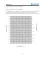
Appendix I: Atmospheric correction formula and chart(Just for reference)...................... 80
Appendix II: Correction for refraction and earth curvature .............................................. 82
Appendix III: Assembling and disassembling for three-jaw tribrach ................................ 83
STANDARD LIMITED WARRANTY............................................................................. 84
Appendix 4 : Environmental recycling ............................................................................. 88
FOR COUNTRIES IN THE EUROPEAN UNION (EU)88Errore. Il segnalibro non è
definito.
FOR COUNTRIES OUTSIDE EUROPEAN UNION (EU) ............................................ 88
3
R2W PLUS
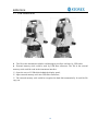
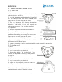
1. Nomenclature and Functions
1.1 Nomenclature
Handle
Handle screw
Optical sight
Eyepiece
Instrument height mark
Vertical
clamp screw
Vertical
motion screw
Battery
Tribrach
USB port
1
R2W PLUS
Objective
Horizontal
motion clamp
Horizontal tangent
screw
Keypad
Touch screen
2
R2W PLUS
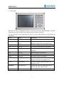
1.2 Keyboard
R2W PLUS series is equipped with two color touch screens and alphanumeric keypad,
operation by both touching screen and pressing keyboard is possible.
Do not touch the screen with ball-pen, pencil or other sharp thing to avoid damage on
instrument.
Keys
Name
Functions
0~9/ A~!
Alphanumeric keypad
Enter text and numerical values.
α
Shift key for character
entry
The current entry method can shift among
number, smaller letter and capital letter.
★
Star key
Normal configurations can be set here
Tab
Tab key
Move the cursor right or next position
BS
BackSpace key
Move the cursor left and delete one
character
Ctrl
Ctrl key
Same with the Ctrl key of PC
Space
Space key
Enter the space
Enter
Enter key
Confirm an entry or selection
ESC
Escape key
Quit a screen or edit mode without saving
changes. Return to next higher level
FUNC
Function key
Perform variable functions defined by
program screen
◄▲▼►
Navigation key
Control the focus bar within the screen
and the entry bar within a field
ⓛ
Power key
Turn on/off the instrument
3
R2W PLUS
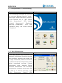
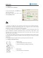
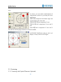
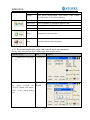
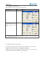
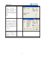
1.3 Comprehensive Understanding
Function introduction
Display
After initiating the instrument the screen will
go to present “Welcome Interface” which is
shown right. STONEX AIOSurvey consists of
several functions, that is, “BSC Measure
(Basic Measurement)”, “STD Measure
(Standard Measurement)”,
“Engineering
Surveying (FieldGenius)”, “INST Setup
(Instrument Setup)” and “About (Relevant
Information)”.
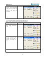
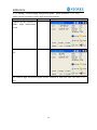
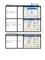
1.3.1 Basic Measurement
Function introduction
Display
Click “BSC Measure” key to activate basic
measuring. This function is used for surveying
and calculating, including some modes, that
is, angle measurement, distance measurement,
coordinate measurement and parameter setting
during conventional surveying. Distance
measurement mode underpins Remote
Elevation Measurement and Line-height
Measurement. Coordinate measurement mode
is made up of Traverse Surveying, Angle
Offset Measurement,
Distance Offset
4
R2W PLUS
Measurement, Plane Offset Measurement, and
Column Offset Measurement.
Besides, basic measurement is also
appropriate for checking performance
functionality and index of angle measurement
and distance measurement for total station.
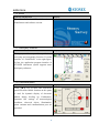
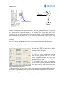
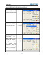
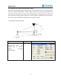
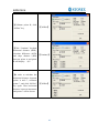
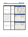
1.3.2 Standard Measurement
Function introduction
Display
Standard measurement function is used to
resolve and calculate applied measurements
during conventional surveying. It contains
“project management”, “import/export”,
“instrument station setup and orientation”,
“foresight
measurement”,
“backsight
measurement”, “side-looking measurement”,
“cross-sectional measurement”, “setting out
of point, bunch and alignment”, “road
design”, “traverse adjustment”, “ coordinate
geometry”, “ batter board label”, “steel ruler
connection survey”, “data query and editing”
and so on.
NOTE: This part is optional, it is normal to
display as right figure.
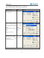
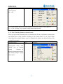
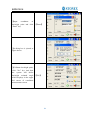
1.3.3 Instrument Setup
Function introduction
Display
Instrument setup function is mainly applied
for instrument settings, instrument calibration
and generation and management of instrument
constant. It is made up of a series of functions
such as “compensator linear correction”,
“compensator zero correction”, “horizontal
axis error correction”, “index correction”,
“instrument settings”, “distance constant
settings”, “communication port settings”,
“configuration management”, etc.
5
R2W PLUS
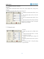
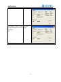
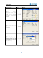
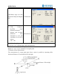
1.3.4 About
Function introduction
Display
The “About” function Offers information of
manufacturer and software version.
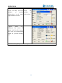
1.3.5 Third-party software
Function introduction
Display
Third-party software provides professional
surveying and cartography function. It’s main
interface of “FieldGenius” in the right figure.
In fact, the application program interface of
STONEX instrument system supports more
third-party softwares.
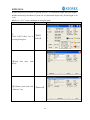
1.3.6 Convenient panel
Function introduction
Display
Click 【★】 key to enter into convenient
panel.Electronic bubble function on this panel
is used for dynamic display of electronic
bubble during leveling up. Furthermore,
functions like settings of meteorological
condition, observed object, illumination,
prism constant and communication port are
provided.
6
R2W PLUS
1.4 Shortcut key
1)Some shortcut keys are applied in R2W PLUS series.
Key combination
Description
⊙
Power on/off
★
Enter into setting mode directly/Turn on the electronic bubble
α
Shift among number, smaller letter and capital letter
FUNC+BS+⊙
Enter this combination at the same time before starting up to
backup all settings
FUNC+CTRL+⊙
Enter this combination at the same time before starting up to
restore all settings
FUNC+SP+⊙
Enter this combination at the same time before starting up to
erase all settings
FUNC+BS
Turn on/off backlight of key panel in face left position
FUNC+TAB
Turn on/off backlight of key panel in face right position
CTRL+ESC
Enter boot menu
CTRL+TAB
Start touch screen calibration
FUNC+CTRL
Turn on/off soft keyboards
FUNC+↑
Increase backlight brightness of LCD
FUNC+↓
Decrease backlight brightness of LCD
FUNC+←
Turn on/off LCD display in face left position
FUNC+→
Turn on/off LCD display in face right position
2) method for character entry switch
Press
α key, current character entry method will be changed, on the lower right corner, the
inputting method will display for a moment.
7
R2W PLUS
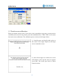
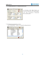
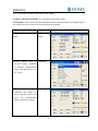
1.5 Touch screen calibration
When you operate on the screen, if your device isn’t responding to your taps, you may need to
recalibrate your screen. In any picture, press the combination key “CTRL+TAB” so as to enter
into touch screen calibration. The calibration process is shown in the figure below.
1) Carefully press and briefly hold stylus on
the center of the target. Repeat as the target
moves around the screen.
2) After all the targets are clicked, the screen
will display as left, tap the screen to register
saved data. The screen goes back to Stylus
Properties menu.
8
R2W PLUS
1.6 Battery
1.6.1 Battery Power indicator
At any screen interface, press【★】key to
open fast setting menu.
Select Battery, battery level will be seen
following Battery Level.
NOTE:
1. The battery’s working time will be affected by many factors, such as ambient temperature,
recharging time, recharging and discharging times. So we suggest the users to fully recharge
the battery or prepare several full batteries before operation.
2. The battery symbol only indicates power capability for current measurement mode. The
power consumption in distance measurement mode is more than in angle mode, if the
instrument enters into distance measurement mode from angle mode, the power maybe
auto-off because of lower battery.
3. The symbol only indicates the supply power but not the instantaneous power change. And if
the measurement mode changes, the symbol will not show the power’s decrease or increase
immediately.
4. It is suggested that user should check every battery power before field work.
1.6.2 Replace and mount battery
1.Replace battery
1)Press the button downward as shown left.
2)Remove the battery by pulling it towards you.
2.Mount battery
1. Insert the battery to the instrument.
9
R2W PLUS
2. Press the top of the battery until you hear a Click.
1.6.3 Recharge battery
1) Connect the charger connector to the battery.
2) Plug the charger on 100V/240V power supply. The red lamp becomes lighting, which
indicates recharging. If interval-time is longer, the connector isn’t fixed well.
3) That the green lamp flashes means recharging is complete.
NOTE: 1) New battery (or battery does not used for several months) should be recharged for
several times. Please recharge it more than 10 hours, and then the battery can attain
best status.
2) Please recharge the battery continuously for another 1~2 hours after the light
turning green, which is good for the battery.
10
R2W PLUS
1.7 USB connection
● The file in the instrument could be read through ActiveSync software by USB cable.
● External memory stick could be used by USB Host connector. The file in the external
memory stick could be read in the instrument interface.
1)Open the cover of USB which behind the display panel;
2)Input external memory stick into USB Host connector;
3)The external memory stick could be recognized as hard disk automatically. It could be file
copy etc.
11
R2W PLUS
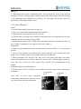
1.8 Guide light (Optional)
Guide light is optional for R2W PLUS Series total station. It is mainly used to stake out.
The Surveyor could adjust the position of prism and station through the guide light color.
It will be faster to set the prism.
The guide light could be seen within 100M. The distance will be effective by atmospheric
conditions and others.
Under the face left situation, the Surveyor should move telescope to left direction when
he only saw the green light or the light became bigger; If only saw the red light or red
light became bigger, the surveyor should move
telescope to the right direction. The move
direction will be contrary when the telescope is
in face right.
Guide light on/off: press【★】to open fast setting
menu, select Battery, if the instrument is
equipped with guide light module, 4 options for
Guide light are active, ①②③ are for adjusting
guide light intensity, select {Off} to turn off
guide light.
12
R2W PLUS
2. Preparation before Measurement
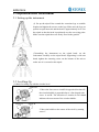
2.1 Setting up the instrument
(1) Set up the tripod first: extend the extension legs to suitable
lengths and tighten the screws on the legs. Make sure the legs are
spaced at equal intervals and the head is approximately level. Set
the tripod so that the head is positioned over the surveying point.
Make sure the tripod shoes are firmly fixed in the ground.
(2)Attaching the instrument on the tripod head: set the
instrument carefully on the tripod head. Supporting it with one
hand, tighten the centering screw on the bottom of the unit to
make sure it is secured to the tripod.
2.2 Levelling-Up
(1) Basic Levelling-Up with the circular level
Screw A
Screw B
1. Move the foot screws A and B in opposite direction till
the circular bubble is perpendicular to a line shaped with
screw A and B. The direction of rotation in left thumb
indicates the movement of the circular bubble.
Screw C
Screw A
Screw B
2. Move the bubble to the center of the circle by turning
screw C.
Screw C
13
R2W PLUS
(2) Accurate Levelling-Up with plate level
Screw B
Screw A
1. Loosen the horizontal motion clamp, and turn the
instrument till the plate level is parallel to a line shaped
with screws A and B. Adjust the screws A and B to
make the bubble in the center of the level.
Plate level
Screw C
Screw B
Screw A
2. Loosen the horizontal motion clamp, and turn the
instrument approximately 90°. Adjust the screw C until
the bubble in the center of the level.
Screw C
3. Repeat above steps until the bubble remains in the
center of the plate level while the instrument is rotated
to any position.
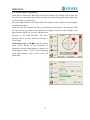
(3) Accurate Levelling-Up with Electronic Level on the screen
It is convenient for R2W PLUS Series to level up with electronic level, especially when it
is difficult to observe the circular level and plate level.
Firstly, press the key 【★】 to turn on the
electronic bubble as shown in left figure. On
the electronic bubble screen, five function
keys are displayed in the left column, which is
listed as follows:
【 TiltXY 】 dynamic display of electronic
bubble
【T.P】observation and setting of temperature
and atmospheric pressure
【Target】target condition of surveying
【Battery】dynamic display of battery level
【Exit】exit the electronic bubble screen
Secondly, level it by turning three foot screws and ensure the bubble is in the plate level.
Make sure the red spot is in the center.
14
R2W PLUS
Note:
As shown, you can realize transformation of
compensation options by pressing the lower
right button.
【XYON】compensate horizontal angle and
vertical angle at the same time
【XONYOFF】just compensate X axis
【XYOFF】don’t compensate X axis and Y
axis
【A.OFF】don’t compensate X axis and Y
axis,and turn off the popup function of electronic bubble.
In STONEX FieldGenius software, the Level
display is always shown as left figure.
2.3 Centering
2.3.1 Centering with Optical Plummet (Optional)
15
R2W PLUS
Cross mark
Plummet
Center
Optical plummet
Turn the focusing ring of the optical plummet to focus the ground mark point. Then adjust
three foot-screws to center the bubble of the circular level. If the plate level is not
leveling-up, you can loosen the center screw of the tripod, and move the instrument to
center the bubble of the plate level. At last tighten the center screw. Repeat above steps
until the center of reticule always coincides with the mark point when rotating alidade of
instrument.
Note: You’d better use the three leveling screws and tripod to center the instrument.
2.3.2 Centering with Laser Plummet
Press the key 【★】 to enter into the display
as shown in the left figure.
Operation Steps:
① Click the “target” button, and you can
turn on laser plummet and set it as three
levels of brightness. Thus, that laser emits
downwards can be seen.
② Loosen the center screw of tripod, and
move the base plate on tripod head until the
laser spot coincides with ground mark point.
Then tighten the center screw.
③ Repeat leveling and two steps until the instrument keeps leveling and the laser spot
coincides with ground mark point when rotating alidade of instrument in any direction.
④ After centering, please turn off laser plummet to save power.
16
R2W PLUS
3 Instrument settings
Instrument settings software is applied for settings and calibration of instrument,
generation and management of instrument constant.It is made up of a series of functions
such as “compensator linear correction”, “compensator zero correction”, “horizontal axis
error correction”, “index correction”, “instrument settings”, “distance constant settings”,
“communication port settings”, “configuration management”, etc.
3.1 INST Setup
Tap ◄ or ► keys to display
other settings
Enter “instrument settings” program by clicking “INST Setup” icon on the desktop. And
then input the password “12345678” to display configuration settings screen. On the
screen tap ◄ or ► keys, different setting screen can be shifted.
NOTE:
This password is open for all users, current configuration settings can be
checked here, but not be adjusted. If you want to adjust these settings, please contact local
distributer or STONEX company.
17
R2W PLUS
3.1.1 Setting the measure condition
Operation:
1. The distance measurement mode will be: Fine, Coarse, Repeat Fine, Average Fine,
Tracking.
2. Tilt correction mode will be: HV, V, NO, Always off.
3. Collimator correction mode will be: Yes or
No.
4. CR correction mode will be: K=0.142,
K=0.2, No.
5. Sea Level correction mode will be: Yes or
No.
6. Target Type mode will be: Prism, No Prism,
Reflector.You could press “Enter” to keep the
setting or press canceled.
3.1.2 Setting the units
Operation:
1. Angle unit mode will be: DMS, GON,
MIL.
2. Angle Precision mode will be: 1 second,
0.1 second or 0.5 second.
3. Distance Unit mode will be: Meter, US
Feet, Feet.
4. Distance precision mode will be: 1mm or
0.1mm.
You could press “Enter” to keep the setting
or press canceled.
18
R2W PLUS
3.1.3 Setting parameters of communication ports
As left shows, click “Other Setup”, you
can activate Bluetooth (BT) and guidelight
(GL), and set parameters of “Bluetooth
Port” and “Phy Port”.
3.1.4 Instrument parameters review
Click “Data Monitor” used for reviewing the setting parameters.
19
R2W PLUS
3.2 Illumination settings
Press the【★】 button and click “Target” and
“Battery” keys in order to go on with
illumination settings including “Cross Light”,
“Guide Light”, and“Laser Point”.
Cross Light: Click this item to turn on the
reticle illumination, and move the slipping
button to adjust reticle illumination.
Guide Light: Click “Battery” key, resulting in
display on which guide light could be
adjusted.
Laser Point: Turn on/off the laser flash before
distance measurement.
20
R2W PLUS
4. Basic measurement program
4.1 Run the program “Basic Measurement”
Current parameters
Function keys
Measurement mode
4.2 Basic measurement screen introduction
The function keys display in the lower left corner of screen, and they vary from one
measurement mode to another. There are some function keys under every measurement
mode being listed in the following table.
Measurement
mode
key
function
S.Zero
Set current horizontal angle as zero
S.Angle
Set current horizontal angle
L.Angle
Lock horizontal angle
Repeat
Retest horizontal angle
V/%
Switch between vertical angle and percent grade
L/R Angle
Horizontal angle switch between left and right
Mode
Set Fine, N Fine, Loop Fine, Track measurement mode
m/ft
Switch among meter, international feet and American feet
in terms of distance unit
Setout
Set out measurement mode
REM
Start REM function
MLM
Start MLM function
LHM
Start LHM function
Mode
Set Fine, N Fine, Loop Fine, Track measurement mode
OCC PT
Set the coordinate of instrument station
S.BS
Set the coordinate of a backsight point
Setup
Set instrument height and target height
21
R2W PLUS
Line
Start traverse surveying
Offset
Start offset measurement (ANG.Offset, DIST Offset,
PLANE Offset, CYL.Offset) function
Coor Order
Set displayed coordinate order as NEZ or ENZ
Save Coor
Save coordinate of instrument station or not
Ang.Unit
Set Ang.Unit as DMS, GON, MIL
Dist Unit
Set Dist Unit as m, UsFeet, IntFeet
Stop
Stop distance measurement
Exit
Exit basic measurement program
4.3 Angle measurement mode
4.3.1 Horizontal angle(right angle) and vertical angle measurements
Firstly, make sure the operation is under angle measurement mode.
Operation steps
Keys
Display
① Collimate the first target
A
Collimate A
②Set horizontal angle as zero
for target A.Click the
“S.Zero” button, and choose
“OK” in the popup dialog
box.
【S.Zero】
【OK】
22
R2W PLUS
③Collimate the second first
target B, and the horizontal
angle and vertical angle will
display on the screen of
instrument.
Collimate B
4.3.2 Horizontal angle switch between right and left
Make sure the operation is under angle measurement mode.
Operation steps
Keys
Display
①Make sure the operation is
under angle measurement
mode
②switch horizontal angle
between left and right by
Clicking “L/R Angle” key
※1
【L/R Angle】
※1 Left angle or right angle will be switched in turn every time you click the “L/R Angle”
key.
23
R2W PLUS
4.3.3 Setting horizontal angle with the “L.Angle” key
Make sure the operation is under angle measurement mode.
Operation steps
Keys
Display
①Turn horizontal circle unit
in the needed direction with
horizontal clamp and tangent
part.
②Click “L.Angle” key, and
activate the function of
locking horizontal angle.
【L.Angle】
③Collimate target point used
for Orientation.
※1
④Click “unclock” key to
deactivate the function of
locking horizontal angle.
Then the screen will return
to
normal
angle
measurement mode, and
meantime horizontal angle
will be set as locked angle.
【Unlock】
※1 Click “Cancel” key before it returns to Previous mode.
24
R2W PLUS
4.3.4 Setting horizontal angle with the “S.Angle” key
Make sure the operation is under angle measurement mode.
Operation steps
Keys
Display
①Collimate target point used
for Orientation.
②Click “S.Angle” key, and a
dialog box will be ejected,
as is showed in the right
figure.
③Input horizontal angle you
need.
【S.Angle】
input
horizontal
angle
※ 1
Such as:232°26' 26"
④With data entry complete,
click “Enter” key, and angle 【Enter】
measurement
after
orientation will go on.
※1 Data entry should be referred to the format shown in the dialog box.
25
R2W PLUS
4.3.5 Setting “vertical angle and percent grade” mode with the “V/%” key
Make sure the operation is under angle measurement mode.
Operation steps
Keys
Display
①Make sure the operation is
under angle measurement
mode.
②Click “V/%” key.
※1
【V/%】
※1 Vertical angle and percent grade will be switched in turn every time you click “V/%”
key.
26
R2W PLUS
4.3.6 Carrying out angle retesting with the “Repeat” key
This program is applied for adding up angle retesting values, displaying the sum and the
average of all observed values, and meantime recording the number of observations.
Operation steps
Keys
①Click “Repeat” key,and
activate angle retesting
function.
【Repeat】
Display
27
R2W PLUS
②Collimate the first target
A.
Collimate A
③Click “S.Zero” key, and
set horizontal angle as
zero.
【S.Zero】
④Collimate the second
target B using horizontal
clamp and tangent part.
Collimate B
28
R2W PLUS
⑤Click “L.Angle” key.
【L.Angle】
⑥Collimate the first target
A again using horizontal
clamp and tangent part.
⑦Click “Unlock” key.
Collimate A
again
【Unlock】
⑧Collimate the second
target B again using
horizontal
clamp
and
tangent part.
⑨Click “L.Angle” key.
And then the screen
displays the sum and the
average of all angles.
※1
Collimate
again
B
【L.Angle】
⑩Repeat steps ⑥ ~ ⑨
according
to
the
requirement, and carry out
angle retesting. ※2
※ 1 Click “Exit” key to finish angle retesting
※ 2 Ht: the sum of multiple observed values
Hm: the average of multiple observed values
29
R2W PLUS
4.4 Distance measurement mode
4.4.1 Distance measurement and measuring mode setting
Operation steps
Keys
①Collimate the center of
prism.
Collimate
②Click “M.Dist” key to
enter distance measurement
mode, and then the system
will carry out measurement
based on previous setting
mode.
【M.Dist】
③Click “Mode” key to
activate setting function of
distance measurement mode.
Take “Loop Fine” as
example here.
【Mode】
Display
Fine: single fine measuring
mode
N Fine: n times fine
measuring mode
Loop Fine: Continuous
measuring mode
Track: tracking measuring
mode
30
R2W PLUS
④Display the
measurement.
※1~※2
result
of
※ 1 Click “mode” key if you wanna change measurement mode, as step ③shows.
※ 2 Click “M.Ang” key to return to angle measurement mode.
4.4.2 Fine/Tracking distance measurement
When you preset the measuring times, the instrument will carry out distance measurement
and display the average distance according to the setting times. If you preset single
observation, the average distance won’t be displayed. In general, the factory default is set
as single observation.
Operation steps
Keys
①Under
distance
measurement mode, click
“Mode” key to activate
setting
function of
distance measurement mode.
The default setting is “single
observation”.
【Mode】
Display
31
R2W PLUS
②Click “N Fine” key with
stylus, and then input the
number
of
needed
observations in the upper
right column of screen.
【N Fine】
input
the
number
of
observations
③Click
“Enter”
key,
collimate the center of
prism, and then the system
will carry out measurement
based on previous setting.
※1
※1 Click “M.Ang” key to return to angle measurement mode.
32
R2W PLUS
4.4.3 Accurate Measurement and Track mode
Accurate Measurement mode: It’s a normal measurement mode.
Track mode: Track mode takes less time than accurate measurement. It is mainly applied
for setting-out survey and useful for tracking moving target.
Operation steps
Keys
①Collimate the center of
prism.
Collimate
prism
②Click “Mode” key to
activate setting function
of distance measurement
mode. And this mode is set
as “Track”.
【Mode】
③Click
“Enter”
key,
collimate the center of
prism, and the system will
carry out measurement
based on previous setting.
【Enter】
Display
33
R2W PLUS
4.4.4 Exchange of distance units
Change distance unit on the screen of distance observation.
Operation steps
Keys
①Click “m/ft” key.
【m/ft】
Display
②Changed distance unit will
display in the upper right
corner. ※1
※1 Distance unit will be exchanged among meter, American feet and international feet
every time you click “m/ft” key.
4.4.5 Distance stake out measurement
This function can display the difference between measured distance and preset distance.
Displayed Value = Observed Value – Standard(Preset) Distance
Setting out among all sorts of distance measurement modes (such as slope distance,
horizontal distance and elevation difference) can be carried on.
34
R2W PLUS
Operation steps
Keys
①Click “Setout” key under
distance measurement mode.
【Setout】
Display
②Select
distance
measurement mode (SD,
HD, VD) to be set out, input
required data and then click
“Enter” key. ※1
③Start setting out.
※1 First of all, a prompt that reminds you to input SD to be set out is displayed in the popup
dialog box. Click “Enter” key to execute SD setting out after inputting data. If you want HD
setting out, need to input zero in “SD dialog box”, click “Enter”, and the system will eject
“HD dialog box” automatically. HD setting out can go on after HD data entry. If you want
VD setting out, need to input zero in both “SD dialog box” and “HD dialog box”, thus the
system will remind you to input elevation difference to be set out.
35
R2W PLUS
4.4.6 Remote Elevation Measurement (REM)
The Remote Elevation program calculates the vertical distance (VD) of a remote object
relative to ground. When using a prism height, the remote elevation measurement will
start from the prism (reference point). If no prism height is used, the remote elevation will
start from any reference point in which the vertical angle is established. In both modes,
the reference point should be perpendicular to the remote object.
1) With prism height (PH) input
Operation steps
Keys
①Under
distance
measurement mode, click
“REM” key to activate
remote
elevation
measurement.
【REM】
Display
36
R2W PLUS
②Select “with PH” button
with stylus.
【with PH】
③Input the prism height
following PH.
Input prism
height
④Collimate the center P of
prism.
⑤Click “M.Dist” key to
start measuring.
⑥Horizontal
distance
between instrument and
prism will be shown.
Collimate
prism
【M.Dist】
37
R2W PLUS
⑦Click “Continue” key, and
position of prism is locked,
that means reference point is
confirmed.
【Continue】
⑧Collimate target K and
click “Continue”, vertical
distance (VD) will be
shown.
※1)
【 Collimate
K】
※1)Click “Exit” key to finish REM.
2) Without prism height input
38
R2W PLUS
Operation steps
Keys
Display
①Select “None PH” button
with stylus.
【None PH】
②Collimate the ground
point.
③Click “M.Dist” key to
start observing.
④Horizontal
distance
between instrument and
prism will be shown.
Collimate
prism
⑤Click “Continue” key, and
position of ground point G is
locked that means reference
point is confirmed.
【Continue】
【M.Dist】
39
R2W PLUS
⑥Click “Continue” key.
【Continue】
⑦Collimate remote target
K.Vertical distance(VD) will
be shown.
※1)
Collimate
target
※1) Click “Exit” to finish REM.
40
R2W PLUS
4.4.7 Missing Line Measurement (MLM)
The Missing Line Measurement program calculates the horizontal distance (dHD), slope
distance (dSD) and elevation (dVD) between two target prisms.
The instrument can accomplish this in two ways:
1. MLM Method (A-B, A-C): Measurement is A-B, A-C, A-D, .........
2. MLM Method (A-B, B-C): Measurement is A-B, B-C, C-D, .........
41
R2W PLUS
Operation steps
①Under
distance
measurement, click “MLM”
key to activate Missing Line
Measurement.
Keys
Display
【MLM】
②Select method (A-B, A-C)
with stylus.
③Collimate prism A,click
“M.Dist” key. Horizontal
distance between instrument
and prism A will be shown.
【M.Dist】
42
R2W PLUS
④Collimate prism B, click
“M.Dist” key.
【M.Dist】
⑤Click “Continue” key,then
horizontal distance (dHD),
elevation difference (dVD)
and slope distance (dSD)
between prism A and prism
B will display. ※1)
【Continue】
⑥In order to calculate the
horizontal distance between
points A and C, collimate
prism C, and click “M.Dist”
key again. Thus horizontal
distance between instrument
and prism C will be shown.
【M.Dist】
43
R2W PLUS
⑦Click “Continue” key,then
dHD, dVD and dSD
between prism A and prism
C will be shown.
【Continue】
※1)Click “Exit” key to return to main menu.
●Procedure of MLM Method (A-B, B-C) is completely same as Method (A-B, A-C)
Method.
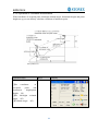
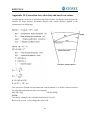
4.4.8 Line-height Measurement
This function is applied for measuring and determining a height of line (like electric wire)
above ground which is hard to reach.
See following image, L is point on the overhead line, G is projective point on the ground,
which is also difficult to set target, A and B are baseline which are set up in a certain
distance under line. After measuring horizontal distances from instrument to prisms A/B
and confirm the base line, VD between A and B, VD between L and G, HD between
instrument and L(G), offset distance from A to L(G) will be determined and shown.
44
R2W PLUS
Operation steps
Keys
Display
①Under
distance
measurement mode, click
“LHM” key to activate
line-height
measurement
program.
【LHM】
②Select “With PH” button
with stylus.
With PH
③Click “Setup” key to input
instrument height (IH) and
prism height (PH). After that
click “Enter” key.
【Setup】
45
R2W PLUS
④Collimate prism A, click
“Measure” key, and distance
measurement begins. After
that click “Continue” key.
【Measure】
⑤Collimate prism B, click
“Measure” key, and distance
measurement begins.
【Measure】
⑥After measurement click
“Continue” key.
【Continue】
46
R2W PLUS
⑦Collimate point L on
overhead line. The screen
displays measuring data of
collimating L.
VD:
Vertical
distance
between A and L.
HD: Horizontal distance
between instrument and L.
Off: Horizontal distance
between A and L.
⑧Click “Continue” key
which is used for measuring
height between overhead
line and ground. Operation
steps:
●Collimate
point
on
overhead
line
before
clicking “Continue” key.
⑨Collimate ground point G
by screwing vertical tangent
part.
【Continue】
Collimate
G
47
R2W PLUS
⑩Click “Continue” key
again, and then height of
overhead
line(LH)
and
horizontal distance(Off) will
display.
※1)~※3)
【Continue】
※1) Click “X” key to end measurement.
※2) Click “VH” key to return to operation step⑦.
48
R2W PLUS
4.5 Coordinate Measurement Mode
4.5.1 Setting coordinate of occupied point
After input coordinate of occupied point (instrument location), unknown point coordinate
will be measured and displayed with this program.
Operation steps
Keys
Display
①Click “M.Coor” key to
enter
coordinate
measurement mode.
【M.Coor】
②Click “OCC PT” key.
【OCC PT】
49
R2W PLUS
③Input
coordinate
of
occupied point from N to Z.
④Finishing data entry,click
“Enter” key and return to
coordinate
measurement
interface.
【Enter】
4.5.2 Setting backsight point
Operation steps
Keys
①Click “S.BS” key to set
backsight point.
【S.BS】
Display
50
R2W PLUS
②Input
coordinate
of
backsight point and click
“Enter” key.
【Enter】
③A dialog box is ejected as
figure shows.
④Collimate backsight point,
click “Yes” key. And then
the system will define
backsight azimuth angle
which displays in the upper
left corner of coordinate
measurement screen.
【Yes】
51
R2W PLUS
4.5.3 Setting instrument height and prism height
Coordinate measurement must be based on instrument height and prism height, thus
coordinate of unknown point can be calculated easily and directly.
Operation steps
Keys
Display
①Click “Setup” key.
【Setup】
②Input instrument height
(IH)and prism height(PH).
Input IH and
PH
③Finishing data entry, click
“Enter” key to return to
coordinate
measurement
screen.
【Enter】
52
R2W PLUS
4.5.4 Operation of coordinate measurement
With coordinate of occupied point, backsight azimuth angle, Instrument height and prism
height set up,you can directly calculate coordinate of unknown point.
Operation steps
Keys
Display
①Set coordinate
of
occupied
point
and
instrument
height/prism
height. ※1)
②Set backsight azimuth
angle. ※2)
③Collimate target. ※3)
53
R2W PLUS
④Click “M.Coor” key to
finish operation.
※4)
【M.Coor】
※1)If don’t input coordinate of occupied point, previous coordinate of occupied point is set
as default. If don’t input instrument height and prism height, the previous is set as default
too.
※2)refer to “4.3.4 Setting horizontal angle with the S.Angle key” or “4.5.2 Setting
backsight point”。
※3)Click “Mode” key to change distance measurement method(Fine/N Fine/Loop
Fine/Track)
※4) Click “M.Angle” or “M.Dist” to return to normal angle or distance measurement mode.
4.5.5 Traverse Surveying
Measure the coordinate of foresight point and save it in the list, this point would be taken
as the occupied point after transferring to point 2, and the previous occupied point will be
taken as the backsight point, the azimuth angle will be calculated and set.
54
R2W PLUS
Set coordinate of occupied point p0 and azimuth angle from point P0 to known point
A.
Operation steps
Keys
①Click “Line” key.
【Line】
②Click “Save” key with
stylus.
【Save】
③Click “Setup” key to reset
instrument height and prism
height. And then click
“Enter” key.
【Setup】
Display
55
R2W PLUS
④Collimate prism in target
point P1 where instrument
will
be
transferred.
Meantime click “Measure”
key.
【Measure】
⑤Click “Continue” key and
coordinate of Point P1
displays in the lower left
corner of screen.
【Continue】
⑥Click
“Save”
key.
Coordinate of P1 can be
ascertained and it will return
to main menu.At last power
off and transfer instrument
to P1(transfer prism from P1
to P0 meantime).
【Save】
56
R2W PLUS
⑦After
instrument
is
established in P1,enter into
traverse
surveying
of
coordinate measurement and
select “Call” button with
stylus.
※1)
⑧Collimate last occupied
point P0. Click “Setup” key,
then coordinate of P1 and
azimuth angle from P1 to P0
will be ascertained. And it
returns to main menu at the
same time.
⑨Repeat steps①~ ⑧, and
carry on according to the
sequence of guidelines till
the end.
※1) Click “Exit” key to finish Traverse Surveying.
57
R2W PLUS
4.5.6 Offset Measurement Mode
There are four kinds of Offset Measurement Modes:
Angle Offset Measurement
Distance Offset Measurement
Plane Offset Measurement
Column Offset Measurement
1) Angle Offset Measurement
This program is used to measure the point where it’s difficult to set prism. Place the prism
at the same horizontal distance from the instrument as that of point A0 to measure.
●When measuring coordinate of ground point A1 (projection of point A0), set instrument
height and prism height.
●When measuring coordinate of point A0,set instrument height only (Prism height is set
as 0).
●Under angle offset measurement mode, there are two methods to set vertical angle:
1. Free vertical angle: vertical angle ranges from up-and-down movement of telescope.
2. Lock vertical angle: vertical angle is locked and can’t range from up-and-down
movement of telescope.
Thus, if collimate A0 with the first method, vertical angle ranges from up-and-down
movement of telescope, and meantime slope distance(SD) and elevation difference(VD)
will change too.But if collimate A0 with the second method, vertical angle is locked in the
direction where prism is located and can’t range from up-and-down movement of
telescope.
58
R2W PLUS
Operation steps
Keys
① Click “Offset” key.
【Offset】
Display
② Click “ANG.Offset” key
in ejecting dialog box.
③ Select “Free VA”(or
“Lock VA”) with stylus
to to start angle offset
measurement.(User
makes a choice on the
basis of own demand)
④ Collimate prism P,and
click “Measure” key.
Collimate
prism P
59
R2W PLUS
⑤Collimate target A0 with
horizontal clamp and tangent
part.
Collimate A0
⑤ Click
“Continue”
key.Then
slope
distance,horizontal
distance and elevation
difference
from
instrument to A0 and
coordinate of A0 will be
shown.
※1),※2)
【Continue】
※1) Click “Setup” key to set instrument height and prism height.
※2)Click “Exit” to finish Angle Offset Measurement
●Set instrument height/prism height before Offset Measurement.
●Refer to “4.5.1” to set coordinate of occupied point.
2) Distance Offset Measurement
The measurement of a target point apart from a prism is possible by inputting offset
horizontal distance of front and back/left and right.
60
R2W PLUS
●When measuring coordinate of ground point A1, set instrument height and prism height.
●When measuring coordinate of point A0, set instrument height only (Prism height is set
as 0).
●Refer to “4.5.1” to set coordinate of occupied point.
Operation steps
Keys
①
Click “DIST Offset” key in
ejecting dialog box.
【DIST
Offset】
Display
②Finish data entry with
stylus.
③Collimate prism and click
“Measure” key.
【Measure】
61
R2W PLUS
④Click “Continue” key,and
result displays with the
correction of offset distance.
※1),※2)
【Continue】
※1) Click “Setup” key to set instrument height and prism height.
※2) Click “Exit” key to finish Distance offset measurement.
3) Column Offset Measurement
It is possible to measure circumscription point (P1) of column directly, the distance to the
center of column (P0), coordinate and direction angle can be calculated by measured
circumscription points P2 and p3. The direction angle of the center of column is 1/2 of
total direction angle of circumscription points P2 and P3.
● Refer to “4.5.1” to set coordinate of occupied point.
62
R2W PLUS
Operation steps
Keys
Display
①
Click “CYL.Offset” key.
【 CYL.Offse
t】
②Collimate the center(P1)
of column surface, and then
click “Measure” key.
【Measure】
③Collimate left point(P2) of
column surface, and then
click “Continue” key.
【Continue】
63
R2W PLUS
④Collimate right point(P3)
of column surface.
②
Click “Continue ” key, and
relational values between
instrument and the center of
column
(P0)
can
be
calculated and shown.
※1),※2)
【Continue】
※1) Click “Setup” key to set instrument height and prism height.
※2) Click “Exit” key to finish column offset measurement.
4) Plane Offset Measurement
Measuring will be taken for the place where direct measuring can not be done, for
example distance or coordinate measuring for an edge of a plane. Three random points
(P1, P2, P3) on a plane will be measured at first in the plane offset measurement to
determine the measured plane, collimate the measuring point (P0), the instrument
calculates and displays coordinate and distance value of cross point between collimation
axis and of the plane.
64
R2W PLUS
● Refer to “4.5.1” to set coordinate of occupied point.
Operation steps
Keys
Display
①
Click “PLANE Offset” key.
【PLANE
Offset】
②Collimate prism P1, and
click “Measure” key.
【Measure】
65
R2W PLUS
③Collimate prism P2, and
click “Measure” key.
【Measure】
④Collimate prism P3, and
click “Measure” key.
【Measure】
⑤Click “Continue” key to
calculate relational values
between collimation axis
and plane.
※1)
【Continue】
※1)Click “Setup” key to set instrument height and prism height.
●If the three observing points can’t determine a plane, the system will display error
message. Thus observe the first point once again.
●When collimation axis doesn’t intersect with determined plane, the system will display
error message.
66
R2W PLUS
4.6 About
Operation:
1. Click “about” icon on desktop.
2. Press “Exit” to return to the basic measurement.
67
R2W PLUS
5. Check and Adjustment
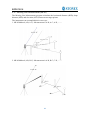
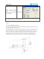
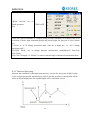
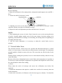
5.1 The Instrument Constant
1) Check
It is suggested to observe and compare the instrument with a testing line which is set on
stable ground with a particular accuracy, though error is not generally included in the
instrument constant. If the testing line is unavailable, you can set it for 20 meters or so by
yourselves, then check and compare it with your new instrument.
AB
A
BC
B
C
AC
1. Select a point B on the approximately horizontal line AC with about 100 meters long.
Measure the distances of lines AB, AC and BC.
2. The instrument constant can be calculated:
instrument constant =AB+BC-AC
3. If there is a difference between the instrument standard constant and the calculated
value, colligate the measured constant and the prism constant to get a new value, then
input the value into the instrument as a prism constant .
4. Compare length of the instrument’s testing line again with a certain standard testing
line .
5. If the difference is over 5 mm after the preceding operations, it is necessary to reset the
instrument constant .
2) Adjustment
About instrument constant setting, you must contact STONEX distributor to do that.
68
R2W PLUS
5.2 Plate Level and Circular Level
5.2.1 Plate Level
1) Check
1. Mount the instrument on a stable device (as tripod,
adjusting device ), and fix it.
2. Level the instrument until the plate level is parallel
to a line linking leveling foot screws A and B, then
adjust the two screws to center the air bubble.
3. Turn the instrument 180°, observe the moving
direction of the bubble, if it is still centered, no
adjustment is necessary, if not, you have to adjust it.
2) Adjustment
1. Mount the instrument on a stable device and fix it.
2. Level it roughly.
3. Turn the instrument and make the plate level be
parallel to a line linking two leveling foot screws, then
adjust the two screws to center the air bubble .
4. Turn the instrument 180°, adjust the Adj-screw with
adjustment pin slightly to correct half of the bubble’s
displacement when it doesn’t move.
5. Repeat the operation (3) and (4) until the air bubble remains centered in any position .
5.2.2 Circular Level
1) Check
1. Mount the instrument on a stable device and fix it.
2. Level it accurately by the plate level.
3. Observe the bubble of the circular level, if it is
centered, no adjustment is necessary, if not, you have
to adjust it.
2) Adjustment
4. Mount the instrument on a stable device and fix it.
5. Level it accurately by the plate level.
6. Adjust the three adjusting screws to center the
bubble by a wrench.
Note: Be careful when adjusting the three screws,
and the tightening tension is identical for them.
69
Circular Level
level Lever
Adjusting pin
R2W PLUS
5.3 The Optical Sight
1) Check
1. Mount the instrument on a tripod and fix it.
2. Set a cross mark target which apart from the
instrument about 50m.
3. Take the telescope sight the cross mark.
4. Observe the optical sight collimator whether
collimating the cross mark, if collimate the mark,
adjustment is not necessary; if not, adjust it.
2) Adjustment
1. Mount the instrument at the tripod and fix it.
2. Set a cross mark target which apart from the
instrument about 50m.
3. Take the telescope sight the cross mark.
4. Loosen two fixing screws, adjust the collimator, then fix the two screws again.
5.4 Optical Plummet and Laser Plummet
5.4.1 Optical Plummet (factory optional)
1) Check
1. Mount the instrument at the tripod and fix it.
2. Set a cross mark under the instrument
3. Coincide the center mark of the optical plummet with the cross mark by adjusting three
leveling foot screws.
4. Turn the instrument 180°, check the center mark and cross mark, if they are coincide,
no adjustment is necessary, if not, adjust it.
2) Adjustment
1. Set the instrument on stable device and fix it.
2. Set a cross mark under the instrument.
3. Use the three leveling screws and coincide the center mark of plummet and cross mark
on the ground.
4. Rotate the instrument 180° around and take off the cover of the optical plummet
eyepiece, adjust the four adjusting screws with the adjusting pin to shift the center mark to
the cross mark, correct only one-half of the displacement in this manner.
(5) Repeat the operation in (3) and (4) until coincide the center mark of the plummet and
cross mark on the ground.
70
R2W PLUS
NOTE:
1. When adjust the screws of plummet reticle, firstly loosen the screw on the moving
direction of reticle, secondly tighten another screw by the same mount, clockwise turning
is for tightening, and anticlockwise turning is for loosening, the turning mount for
tightening or loosening should be same.
5.4.2 Laser Plummet
Check
(1) Set the instrument on stable device and fix it.
(2) Set a cross mark on the ground under the instrument.
(3) Turn the laser switch on and focus it accurately.
(4) Turn the three leveling screws until the instrument keeps leveling and the laser spot
coincides with the cross mark on the ground.
(5) Rotate the instrument 180° (200g) around and check the laser spot and cross mark, if
they coincide, adjustment is not required. Otherwise, adjust it.
Adjustment
1. Setting up the instrument on the checking tool or tripod which is 1.5m apart from
ground.
2. Turn on laser plummet, turn tribrach foot screws until laser spot coincide with cross
mark. If you use tripod, make a cross mark on the laser spot directly.
3. Rotate instrument 180° around, if the laser spot is over 2mm apart from cross mark,
remove the protecting cover firstly, adjust two screws with 1.5mm hexagon wrench to
move laser spot to the cross mark, correct only one-half of the displacement in this
manner.
Adjusting details see attached figure.
4. Repeat steps 2 and 3 until laser spot coincides with cross mark always when rotate
instrument.
Un-adjustable
Adjustable
screw
screw
Note: there are three screws amounted
around laser plummet part, only two screws
are used for laser accuracy adjustment.
71
R2W PLUS
5.5 Vertical Cross-hair on Telescope
1) Check
(1) Set the instrument up the tripod and carefully level it;
(2) Set a point A front the instrument 50m apart;
(3) Collimate the point A and adjust the vertical tangent screw; If the point appears to
move continuously on the hair, adjustment is not required. Otherwise, adjust it.
2) Adjustment
(1) Set the instrument, and set the point A front the instrument 50m apart.
(2) Take off cover of telescope eyepiece, there are 4 screws for the reticle part.
(3) Loosen all four fixing screws slightly with the cross screw-drive.
(4)Revolve the eyepiece section so that the vertical cross-hair coincides to point A, finally,
re-tighten the four screws.
(5) Repeat the checking and adjusting until there is no deviation.
NOTE:
1)After the adjustment of cross-hair, please check the collimation error and vertical index
error.
2) Refer to the chapter “5.9 EDM Optical Axis and the Telescope Sighting Axis Error” to
check the axis. At last check the collimator error again.
72
R2W PLUS
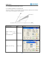
5.6 Horizontal Collimation Error C
If the telescope’s sight line isn’t perpendicular to the horizontal axis, the collimation error
will appear. The assembling, transportation and operation will cause this error.
If the collimation error isn’t over the permitted range, with the program the instrument
can correct this collimation error.
NOTE: After the program correction this deviation error is also on the instrument.
1) Check
(1) Set-up the instrument on tripod or adjustment platform and leveling accurately.
(2) Aim at the cross-hairs of collimator or the obvious target at a distance. Get the face
left angle reading H1 and the face right angle reading Hr.
(3) Calculating the horizontal collimation error C according to C = (Hl - Hr ± 180°)/2, if
C<8″, no adjustment will be necessary. If C>8″, proceed with the following adjustment.
2) Adjustment by program:
Set-up the instrument on tripod or adjustment platform, and leveling accurately.
Procedures:
1. Power on, run the software “INST Setup”, on the screen tap ◄ or ► keys until
Collimation displays, tap it to display collimation error and vertical index error setting
menu.
2. Aim at the cross-hair of collimator at telescope left, tap “Left value” to read the
horizontal and vertical angles.
3. Aim at the cross-hair of collimator at telescope right, tap “Right value” to read the
horizontal and vertical angles.
4. The software will calculate the new collimation error and vertical index error
automatically.
5. Tap “Enter” to save the new values, or tap “Cancel” to use old values.
Note:
The adjustment can be performed by the program when C<30″, if C>30″, adjust the
73
R2W PLUS
reticle.
Reticle Adjusting:
1. Rotate the instrument in face right position, turning horizontal tangent screw until Hr′ =
Hr+C.
2. Loosen the shield of telescope’s reticle.
3. Adjusting two screws at left and at right until the vertical hairs of telescope’s reticle
coincides with the cross-hairs of collimator or target.
4. Repeat the check and adjustment procedure until the error is accepted.
NOTE:
1. When adjusting the screws of reticle, firstly loosen the screw on the moving direction
of reticle, secondly tighten another screw by the same mount, clockwise turning is for
tightening, and anticlockwise turning is for loosening, the turning mount for tightening or
loosening should be same.
2. After the reticle adjustment, it is necessary to adjust the vertical index error by
program.
5.7 Vertical Index Error
The deviation between vertical circle zero position and horizontal direction is vertical
index (i), it is necessary to concern this error when measure vertical angle. The instrument
program applied a formula to remove this error. This correction can offer the index for the
formula.
Warning: Before starting this operation, be sure to read manual carefully, otherwise it may
cause data faulty.
Because of the close relationship between vertical index and compensator zero position, it
is necessary to check and adjust compensator zero position when adjust the vertical circle,
the value should be stable when reading.
1) Check:
Please adjust the reticle of telescope and correct the collimation error before this
operation.
(1) Mount the instrument at the tripod or a stable device and level it accurately, then turn
on the instrument.
(2) Aim at the cross-hairs of collimator or the obvious target at a distance, VA should be
74
R2W PLUS
about ±10°. Read the face left angle Vl and face right angle Vr.
(3) Calculate the index error according to the formula below:
i = ( Vl+Vr-360°)/2
(4)If I<10”, no adjustment is necessary, or you have to adjust it .
2) Adjustment by program:
Set-up the instrument on tripod or adjustment platform, and leveling accurately.
Procedures
1. Power on, run the software “INST Setup”, on the screen tap ◄ or ► keys until
Collimation display, tap it to display collimation error and vertical index error setting
menu.
2. Aim at the cross-hair of collimator at telescope left, tap “Left value” to read the
horizontal and vertical angles.
3. Aim at the cross-hair of collimator at telescope right, tap “Right value” to read the
horizontal and vertical angles.
4. The software will calculate the new collimation error and vertical index error
automatically.
5. Tap “Enter” to save the new values, or tap “Cancel” to use old values.
75
R2W PLUS
5.8 EDM Optical Axis and the Telescope Sighting Axis Error
It is necessary to check this error after the adjustment of telescope reticle error.
1)Checking
(1) Install the instrument at the tripod or a stable device and level it accurately, then
power on the instrument.
(2) Set a prism about 2m far away from the instrument.
(3) Aim at the prism center with telescope reticle.
(4) Enter EDM signal testing screen.
(5) Observe through eyepiece, turn the focusing knob until the red mark is clear, if the
deviation between mark and cross-hair is not over 1/5 of red mark diameter, adjustment is
unnecessary.
2)Checking (For R2W PLUS Series)
(1) Install the instrument at the tripod or a stable device and level it accurately, then
power on the instrument.
(2) Set a reflective sheet about 5m~20m far away from the instrument.
(3) Aim at the sheet cross-mark with telescope reticle.
(4) Enter EDM signal testing screen.
(5) Observe the laser spot, if the laser spot coincides with the cross-mark of reflective
sheet, adjustment is unnecessary.
NOTE:
Laser radiation do not stare into beam.
3)Adjustment
If the instrument needs adjustment, please contact with our dealers.
76
R2W PLUS
6. Specifications
R2W PLUS Series
Telescope
Length
156mm
Image
Erect
Magnification
30×
Objective aperture
Field of view
ɸ45mm
Minimum focus
1.0m
1°30’
Angle measurement
Reading system
Absolute encoder
Circle diameter
79mm
Angle unit
360°(dms/d)/400gon/6400mil, selectable
Display resolution
1” / 0.0002gon/0.005mil, selectable
Detecting mode
Double
Accuracy
2″/5″
Distance measurement
Display resolution(m/inch selectable)
0.1mm/1mm
Laser class
Prism
Class 1
Reflectorless / Reflective sheet
Class 3R
Distance unit
m/ft/US ft, selectable
Measurement range(good condition)
Single prism
1 to 3000m
Reflective sheet/RP60
1 to 800m
Reflectorless
1 to 500m
Mini-reading
Accuracy
Fine mode
0.1mm/1mm(0.001ft/0.01ft)
Tracking mode
10mm (0.1ft)
Prism
2mm+2ppm
Reflective sheet/RP60
3mm+2ppm
Reflectorless
1-200m:3mm+2ppm
≥200: 5mm+3ppm
Measurement time
Initial: 2.5sec
Fine mode: 1.5 sec
Rapid mode: 0.9sec
Tracking mode: 0.5sec
Prism
typ: 1.0-1.5sec
Reflective sheet/Rp60
typ: 1.5sec
77
R2W PLUS
Reflectorless
typ: 1.5-5sec, max.20sec
Temperature unit
℃/℉, selectable
Pressure unit
hPa/mmHg/inchHg, selectable
Temperature input range
-30℃ to +60℃ (1℃ steps)
Pressure input range
510hPa to 1066hPa(1hPa setps)
Prism constant condition
-99.9mm to +99.9mm
Refraction and earth curvature correction
OFF/0.14/0.2, selectable
Reflecting prism constant correction
-99.9mm to +99.9mm
Level vial sensitivity
Plate level
30″/2mm
Circular level
8′/2mm
Compensation
Dual-axis
System
Liquid type
Range
±3′
Resolving power
1″
Data processing system
Operating system
Windows CE
CPU
32 bit
Optical plummet(Factory optional)
Accuracy
±0.8mm/1.5m
Image
Erect
Magnification
3×
Focusing range
0.5m~∝
Field of view
4°
Laser plummet(Standard)
Accuracy
±1.0mm/1.5m
Laser class
Class 2/IEC60825-1
Laser spot size/brightness
Adjustable
Laser wave length
635nm
Display
Touch screen
Two sides, 3.5" color TFT LCD (320 x 240 dots)
Power
Battery
3400 mAh Li-ion Rechargeable battery
Voltage
7.4V DC
Continuous operation time
About 10 hours(single distance measurement every
30 seconds)
Chargers
FDJ6-Li(100V to 240V )
78
R2W PLUS
Charging time (at +20℃)
Approx. 4 hours
Application programs
Data collection/Stake out/Resection/REM/MLM/Point to line
AREA/Z coordinate/OFFset/3D Road/Traverse adjustment
Tape measurement/section/axis positioning measurement
Others
CPU
Memory
ARM9 Core
2GB internal memory
Guide Light System
Factory optional
Sensors
Built-in temperature and pressure sensors
Keyboard
Alphanumerical illuminated key board,both sides
Operating temperature
Storage temperature
-20°~+50℃
-40°~+70℃
Dimension(W×D×H)
185×220×360mm
Weight(including batteries)
5.5kg
Dimensions(W×D×H)
185×220×360mm
Interface
USB host/USB slave/RS-232C/Bluetooth(Optional)
Water and dust protection
IP55 (IEC60529)
Data collector
PS236, fully rugged PDA(Optional)
79
R2W PLUS
7. Standard components
● Carrying case
1 each
● Instrument
1 each
● Battery
2 each
● Charger
1 each
● Tools bag
1 each
● Adjusting pin
2 each
● Cleaning cloth
1 each
● Cleaning brush
1 each
● Screwdriver
1 each
● Wrench
2 each
● Silica gel
1 each
● CD
1 each
● USB Communication cable
1 each
● Rainproof
1 each
● Reflective sheet/RP30
4 each
● Reflective sheet/RP60
1 each
● Laser caution sign board
1 each
● Touch pen
2 each
● Tribrach
1 each
Appendix I: Atmospheric correction formula and chart(Just
for reference)
Factory setting:
temperature: 20℃, pressure:1013hpa, 0ppm
temperature: 20℃, pressure:1013hpa, 0ppm
The correction:
Kpt=274.417-0.2905*p/(1+0.0036*t)
Kpt=278.960-0.2902*p/(1+0.0036*t)
Where: p--Pressure value (hPa)
t--Temperature value (℃)
Kpt--Atmospheric correction (ppm)
Example:
t=20℃, p=1013hpa, L0=1000m.
Then:
Kpt=0ppm
Kpt=4ppm
80
R2W PLUS
L=L0(1+Kpt)=1000×(1+0×10-6)=1000.000m
L=L0(1+Kpt)=1000×(1+4×10⁻⁶)=1000.004m
The atmospheric value is obtained easily with the atmospheric correction chart. Find the
measured temperature in horizontal axis, and pressure in vertical axis on the chart.
Read the value from the diagonal line, which is the required atmospheric correction value.
81
R2W PLUS
Appendix II: Correction for refraction and earth curvature
Considering the correction of refraction and earth curvature for distance measurement, the
formula for slope distance, horizontal distance and vertical distance applied in the
instrument are as followings:
The conversion formula for horizontal and vertical distance is as follows when correction
for refraction and earth curvature is not applied:
HD=SD COS§
VD=SD ∣SIN§∣
NOTE:
The factory setting for the refraction coefficient K is 0.142.
Refer to the section 3.10 to change the value of K.
82
R2W PLUS
Appendix III: Assembling and disassembling for three-jaw
tribrach
It is convenient to assemble or disassemble the instrument from tribrach by loosen or
tighten the tribrach clamp.
Disassemble
(1) Rotate the tribrach clamp anticlockwise until the lever is loosen.
(2) One hand hold up the tribrach, another hand hold the carry handle of the instrument
and lift out the instrument from the tribrach.
Assemble
(1) Put the instrument into the tribrach lightly, let the communication port against in the
indentation of the tribrach.
(2) Rotate the tribrach clamp clockwise until the lever is tighten.
Positing block
Positing groove
Tribrach clamp
Fixed screw
83
R2W PLUS
Note: Fix the tribrach clamp
If the instrument don’t need assembly or disassembly from tribrach frequently, it is
necessary to fix the tribrach clamp by fixed screw to avoid the disassembly by accident.
Screw out the fixed screw by driver to fix the clamp.
NOTE:
These designs, figures and specifications are subject to change without notice.
We shall not be held liable for damages resulting from errors in this instruction
manual.
STANDARD LIMITED WARRANTY
General Warranty for Instruments.
The terms and conditions of this Limited Warranty constitute the complete and exclusive
warranty agreement between The Customer or Dealer and STONEX® for the Product and it
supersedes any prior agreement or representation made in any STONEX® sales document or
advice that may be provided to Customer by any STONEX® representative in connection with
Customer’s purchase of the Product. No change to the conditions of this Limited Warranty is
valid unless it is made in written form and signed by an authorized STONEX® supervisor.
STONEX ® Europe warrants that its Products:
① are free from defects in materials or workmanship for generally 2 year
except for
accessories or specific parts for which different limited warranty period shall apply .
② have been tested/calibrated in proper working status prior to shipment.
The warranty period starts from date of first sale of the instruments. At its sole discretion,
under the warranty period, STONEX® Europe will repair the product or send parts for
replacement at its expense. STONEX® Europe agree to repair or replace the defected
instrument within thirty (30 ) days, only if STONEX® Europe recognizes that the defects of
the instrument are not caused by human factors or no obvious damage to its surface is visible.
STONEX® Europe warrants any new replaced parts or products are warranted to be free from
defects in materials and workmanship for thirty (30) days or for the remainder of the Limited
Warranty Period of the Product in which they are installed, whichever is longer. Faulty Parts or
84
R2W PLUS
Products replaced under this Limited Warranty shall become property of STONEX® Europe.
All products that have to be repaired have to be returned to our technical representative office
location via any delivery company the customer prefers.
NOTE: STONEX® Europe is not accountable for the unlikely event that the Products gets lost
in transit.
Any damage inflicted by the customer or by third party after the products has been delivered
to the customer is excluded from the limited warranty as well any damage arising from an
improper use, from any action or use not provided for in the enclosed user guides and/or
manuals.
Shipping policy.
The Customer or the dealer is required to pay for the charges for shipping of fault
parts or instruments to STONEX® Europe representative office and STONEX®
Europe (will provide) the shipping for return. Dealers needs to follow STONEX ® Europe
repair/service procedure (see appendix 4) to achieve a better and prompt service result.
Return policy Dead On Arrival instruments.
All returned products have to be shipped to STONEX® Europe representative office.
The original Purchaser has a period of seven (7) days, starting from date (data) of purchasing
to signal the existence of a defect in the instrument for a full refund (less shipping and
handling), provided the merchandise is in new, resalable condition and returned in the original,
undamaged packaging. Customer has to pay for both the return and the original freight fees,
regardless of the original freight paid by the Company. All warranty books, instruction
manuals, parts and accessories must be included as well as the original box in which the item
was shipped. We recommend to place the original carton inside another box, to avoid any
additional damage to the carton itself. In some cases, returns of special items will require a
re-stock fee . Acceptance of returned merchandise is final only after inspection by STONEX®
Europe.
Above terms and (policy shall apply as for hardware.) Dealers needs to follow STONEX ®
Europe repair/service procedure (see appendix 4) to achieve a better and prompt service result.
Firmware/Software warranty.
Stonex Europe doesn’t warrant that operation of Firmware/Software on any instruments will
be uninterrupted or error-free, or that functions contained in Firmware/Software will operate to
85
R2W PLUS
meet your requirements.
Stonex will forward the Software/Firmware Fix to the dealer or customer. Firmware/software
Fix means an error correction or other update created to fix a previous firmware version that
substantially doesn’t conform to the instruments specification.
Over Warranty repair(s) policy.
Customer shall pay the standard repair fees for any service (whether part replacement or
repairs) and performed by STONEX® Europe under request and explicit authorization of the
customer itself. In this case the customer is charged for return shipment’s fees as well.
Disclaimer and Limitation of Remedy.
ALL OTHER EXPRESS AND IMPLIED WARRANTIES FOR THIS PRODUCT,
INCLUDING THE IMPLIED WARRANTIES OF MERCHANTABILITY AND FITNESS
FOR A PARTICULAR PURPOSE AND/OR NONINFRINGEMENT OF ANY THIRD
PARTY’S RIGHTS, ARE HEREBY DISCLAIMED. STONEX® EXPRESSLY DISCLAIMS
ALL WARRANTIES NOT STATED IN THIS LIMITED WARRANTY. ANY IMPLIED
WARRANTIES THAT MAY BE IMPOSED BY LAW ARE LIMITED IN DURATION TO
THE TERM OF THIS LIMITED WARRANTY. SOME JURISDICTIONS DO NOT ALLOW
THE EXCLUSION OF IMPLIED WARRANTIES OR LIMITATIONS ON HOW LONG AN
IMPLIED WARRANTY LASTS, SO THE ABOVE EXCLUSIONS OR LIMITATIONS MAY
NOT APPLY TO CUSTOMER. CUSTOMER MUST READ AND FOLLOW ALL SET-UP
AND USAGE INSTRUCTIONS IN THE APPLICABLE USER GUIDES AND/OR
MANUALS ENCLOSED. IF CUSTOMER FAILS TO DO SO, THIS PRODUCT MAY NOT
FUNCTION PROPERLY AND MAY BE DAMAGED. CUSTOMER MAY LOSE DATA OR
SUSTAIN PERSONAL INJURIES. STONEX®, ITS AFFILIATES AND SUPPLIERS DO
NOT WARRANT THAT OPERATION OF THIS PRODUCT WILL BE UNINTERRUPTED
OR ERROR FREE; AS DO ALL ELECTRONICS AT TIMES. IF THIS PRODUCT FAILS
TO WORK AS WARRANTED ABOVE, CUSTOMER’S SOLE AND EXCLUSIVE
REMEDY SHALL BE REPAIR OR REPLACEMENT. IN NO EVENT WILL STONEX ®,
ITS AFFILIATES OR SUPPLIERS BE LIABLE TO CUSTOMER OR ANY THIRD PARTY
FOR ANY DAMAGE IN EXCESS OF THE PURCHASE PRICE OF THE PRODUCT. THIS
LIMITATION APPLIES TO DAMAGES OF ANY KIND WHATSOEVER INCLUDING (1)
DAMAGE TO, OR LOSS OR CORRUPTION OF, CUSTOMER’S RECORDS, PROGRAMS,
DATA OR REMOVABLE STORAGE MEDIA, OR (2) ANY DIRECT OR INDIRECT
DAMAGES, LOST PROFITS, LOST SAVINGS OR OTHER SPECIAL, INCIDENTAL,
EXEMPLARY OR CONSEQUENTIAL DAMAGES, WHETHER FOR BREACH OF
WARRANTY, CONTRACT, TORT OR OTHERWISE, OR WHETHER ARISING OUT OF
THE USE OF OR INABILITY TO USE THE PRODUCT AND/OR THE ENCLOSED USER
86
R2W PLUS
GUIDES AND/OR MANUALS, EVEN IF STONEX®, OR AN AUTHORIZED STONEX®
REPRESENTATIVE, AUTHORIZED SERVICE PROVIDER OR RESELLER HAS BEEN
ADVISED OF THE POSSIBILITY OF SUCH DAMAGES OR OF ANY CLAIM BY ANY
OTHER PARTY. SOME JURISDICTIONS DO NOT ALLOW THE EXCLUSION OR
LIMITATION OF INCIDENTAL OR CONSEQUENTIAL DAMAGES FOR SOME
PRODUCTS, SO THE EXCLUSIONS OR LIMITATIONS MAY NOT APPLY TO
CUSTOMER. THIS LIMITED WARRANTY GIVES CUSTOMER SPECIFIC LEGAL
RIGHTS, AND CUSTOMER MAY ALSO HAVE OTHER RIGHTS WHICH VARY FROM
COUNTRY/STATE/JURISDICTION TO COUNTRY/STATE/.
Two (2) years on STONEX® Product:
Total Station R2W excluding battery supply accessories ( 6 months ) .
Repair/Service procedure for dealers.
(1) S/N of the instrument and a detailed description of the defect (sometimes pictures or
video) will be required to indicate the cause and problem.
(2) If dealer wants to repair an instrument under warranty period on their site:
1) If dealers (don’t) have the part in stock they have to send an official order to STONEX®
Europe and pay for it and then so STONEX® Europe will send the new part to them so they
can repair the instrument.
2) When the repair is over dealer has to fill the “Spare Part Refund” module and send it to the
dedicated mail address.
3) wait for STONEX® Europe’s authorization SPR no;
4) when dealer receives the SPR authorization number they can send back to STONEX®
Europe appointed office the broken part with attached the SPR module;
5) when STONEX® Europe receive the broken part STONEX® Europe shall verify it and if
everything is ok the cost of the part shall be refund ( refund will be done only after
check of
the failure part and final approval of STONEX® Europe).
(3) If the instrument needs to be sent back to STONEX® Europe for repair/replacement,
dealers/customers has to send to STONEX® Europe a “Returned Merchandise Authorization
(RMA)” before they send back the fault instrument. STONEX® Europe shall, at its sole
discretion, decide on the place of performance for work under warranty.
87
R2W PLUS
Appendix 4 : Environmental recycling
The cardboard box, the plastic in the package and the various parts of this product have to be
recycled and disposed of in accordance with the current legislation of your Country.
FOR COUNTRIES IN THE EUROPEAN UNION (EU)
The disposal of electric and electronic device as solid urban waste is strictly prohibited: they
must be collected separately.
Contact Local Authorities to obtain practical information about correct handling of the waste,
location and times of waste collection centres. When you buy a new device of ours, you can
give back to our dealer a used similar device.
The dumping of these devices at unequipped or unauthorized places may have hazardous
effects on health and environment.
The crossed dustbin symbol means that the device must be taken to authorized collection
centers and must be handled separately from solid urban waste.
FOR COUNTRIES OUTSIDE EUROPEAN UNION (EU)
The treatment, recycling, collection and disposal of electric and electronic devices may vary in
accordance with the laws in force in the Country in question.
88
R2W PLUS
Stonex Europe Srl.
Via Cimabue 39, 20851 Lissone (MB), Italy
Phone: +390392783008; +390392785575
Fax: +390392789576
Email: [email protected]
Web:www.stonexpositioning.com
89