1
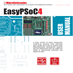
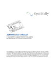
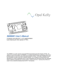
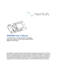
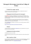
PRELIMINARY CCG1 Datasheet USB Type-C Port Controller with Power Delivery General Description CCG1 provides a complete USB Type-C and USB Power Delivery port control solution. The scalable and reconfigurable core architecture of CCG1 enables a base Type-C solution that can scale to a complete 100-W USB Power Delivery with Alternate Mode mux support. CCG1 is also a Type-C cable ID IC for active and passive cables. The ARM® Cortex®-M0 CPU based core can use common open source firmware or custom solutions developed with common libraries and APIs. CCG1 is the CC controller that detects connector insert, plug orientation, and VCONN switching signals. CCG1 makes it easier to add USB Power Delivery to any architecture because it provides the control signals to manage external VBUS and VCONN power management solutions as well as external mux controls for most single cable-docking solutions. CCG1's packaging options, and programmability, enables any USB Type-C and USB Power Delivery solution. Applications Type-C Support ■ Notebooks, tablets, monitors, docking stations ■ ■ Power adapters, USB Type-C cables ■ ■ Features PD Support ■ 32-bit MCU Subsystem ■ Integrated transceiver (BB PHY) Supports up to two USB ports with PD Supports routing of all protocols through an external mux ■ 48-MHz ARM Cortex-M0 CPU with 32-KB flash and 4-KB SRAM Supports Provider and Consumer roles Supports all power profiles Low power operation Integrated analog blocks ■ 12-bit, 1-Msps ADC for VBUS voltage and current monitoring ■ Dynamic overcurrent and overvoltage protection ■ Integrated digital blocks ■ Two configurable 16-bit TCPWM blocks 2 ■ One I C master or slave ■ ■ 1.8-V to 5.5-V operation Sleep 1.3 mA, Deep Sleep 1.3 uA Packages ■ ■ 40-pin QFN 16-pin SOIC 35-ball wafer-level CSP (WLCSP) Figure 1. CCG1 Block Diagram [1, 2, 3, 4, 5, 6] CCG1: USB Type-C Port Controller with PD MCU Subsystem Integrated Analog Blocks I/O Subsystem CC 48 MHz Flash (32KB) SRAM (4KB) Serial Wire Debug ADC Rp4, Rd5, Ra6 Control Comparators Integrated Digital Blocks TCPWM1 SCB2 (I2C) Profiles and Configurations BB3 MAC Programmable Interconnect and Routing CORTEX-M0 Advanced High-Performance Bus (AHB) IDAC VBUS Control VCONN Control Voltage Select MUX Control Current Control Device Detect VBUS Sense VCONN Sense BB3 PHY GPIOs Notes 1. Timer, counter, pulse-width modulation block. 2. Serial communication block configurable as I2C. 3. Base band. 4. Termination resistor denoting a Downstream Facing Port (DFP). 5. Termination resistor denoting a Upstream Facing Port (UFP). 6. Termination resistor denoting an Electronically Marked Cable Assembly (EMCA). Cypress Semiconductor Corporation Document Number: 001-93639 Rev. *E • 198 Champion Court • San Jose, CA 95134-1709 • 408-943-2600 Revised March 13, 2015 PRELIMINARY CCG1 Datasheet Contents Functional Definition ........................................................ 3 CPU and Memory Subsystem ..................................... 3 System Resources ...................................................... 3 GPIO ........................................................................... 3 Pin Definitions .................................................................. 4 Pinouts ............................................................................ 11 Power ............................................................................... 12 Electrical Specifications ................................................ 14 Absolute Maximum Ratings ....................................... 14 Device Level Specifications ....................................... 14 Digital Peripherals ..................................................... 17 Memory ..................................................................... 18 System Resources .................................................... 18 Applications in Detail ..................................................... 20 Document Number: 001-93639 Rev. *E Ordering Information ...................................................... 27 Ordering Code Definitions ......................................... 27 Packaging ........................................................................ 28 Acronyms ........................................................................ 31 Document Conventions ................................................. 32 Units of Measure ....................................................... 32 Revision History ............................................................. 33 Sales, Solutions, and Legal Information ...................... 34 Worldwide Sales and Design Support ....................... 34 Products .................................................................... 34 PSoC® Solutions ...................................................... 34 Cypress Developer Community ................................. 34 Technical Support ..................................................... 34 Page 2 of 34 PRELIMINARY Functional Definition CPU and Memory Subsystem CPU The Cortex-M0 CPU in the CCG1 is part of the 32-bit MCU subsystem, which is optimized for low-power operation with extensive clock gating. It mostly uses 16-bit instructions and executes a subset of the Thumb-2 instruction set. This enables fully compatible binary upward migration of the code to higher performance processors such as the Cortex-M3 and M4, thus enabling upward compatibility. The Cypress implementation includes a hardware multiplier that provides a 32-bit result in one cycle. It includes a nested vectored interrupt controller (NVIC) block with 32 interrupt inputs and a Wakeup Interrupt Controller (WIC). The WIC can wake the processor up from the Deep Sleep mode, allowing power to be switched off to the main processor when the chip is in the Deep Sleep mode. The Cortex-M0 CPU provides a Non-Maskable Interrupt (NMI) input, which is made available to the user when it is not in use for system functions requested by the user. The CPU also includes a debug interface, the serial wire debug (SWD) interface, which is a 2-wire form of JTAG; the debug configuration used for CCG1 has four break-point (address) comparators and two watchpoint (data) comparators. Flash The CCG1 device has a flash module with a flash accelerator, tightly coupled to the CPU to improve average access times from the flash block. The flash block is designed to deliver 1 wait-state (WS) access time at 48 MHz and 0-WS access time at 24 MHz. The flash accelerator delivers 85% of single-cycle SRAM access performance on average. Part of the flash module can be used to emulate EEPROM operation if required. SROM A supervisory ROM that contains boot and configuration routines is provided. FIFO for receive and transmit which, by increasing the time given for the CPU to read data, greatly reduces the need for clock stretching caused by the CPU not having read data on time. The I2C peripheral is compatible with the I2C Standard-mode, Fast-mode, and Fast-mode Plus devices, as defined in the NXP I2C-bus specification and user manual (UM10204). The I2C bus I/O is implemented with GPIO in open-drain modes. The CCG1 is not completely compliant with the I2C spec in the following respects: ■ GPIO cells are not overvoltage tolerant and, therefore, cannot be hot-swapped or powered up independently of the rest of the I2C system. ■ Fast-mode Plus has an IOL specification of 20 mA at a VOL of 0.4 V. The GPIO cells can sink a maximum of 8 mA IOL with a VOL maximum of 0.6 V. ■ Fast-mode and Fast-mode Plus specify minimum Fall times, which are not met with the GPIO cell; Slow strong mode can help meet this spec depending on the Bus Load. ■ ■ The CCG1 has one SCB, which can implement an I2C interface. The hardware I2C block implements a full multi-master and slave interface (it is capable of multimaster arbitration). This block is capable of operating at speeds of up to 1 Mbps (Fast Mode Plus) and has flexible buffering options to reduce interrupt overhead and latency for the CPU. It also supports EZ-I2C that creates a mailbox address range in the memory of the CCG1 and effectively reduces I2C communication to reading from and writing to an array in memory. In addition, the block supports an 8-deep Document Number: 001-93639 Rev. *E When the SCB is in the I2C Slave mode, and Address Match on External Clock is enabled (EC_AM = 1) along with operation in the internally clocked mode (EC_OP = 0), then its I2C address must be even. The CCG1 has 34 GPIOs, which are configured for various functions. Refer to the pinout tables for the definitions. The GPIO block implements the following: ■ Eight drive strength modes: ❐ Analog input mode (input and output buffers disabled) ❐ Input only ❐ Weak pull-up with strong pull-down ❐ Strong pull-up with weak pull-down ❐ Open drain with strong pull-down ❐ Open drain with strong pull-up ❐ Strong pull-up with strong pull-down ❐ Weak pull-up with weak pull-down ■ Input threshold select (CMOS or LVTTL). ■ Individual control of input and output buffer enabling/disabling in addition to the drive strength modes. ■ Hold mode for latching previous state (used for retaining I/O state in Deep Sleep mode). ■ Selectable slew rates for dV/dt related noise control to improve EMI. Power System Serial Communication Blocks (SCB) When the SCB is an I2C Master, it interposes an IDLE state between NACK and Repeated Start; the I2C spec defines Bus free as following a Stop condition so other Active Masters do not intervene but a Master that has just become activated may start an Arbitration cycle. GPIO System Resources The power system is described in detail in the section Power on page 12. It provides assurance that voltage levels are as required for each respective mode and either delay mode entry (on power-on reset (POR), for example) until voltage levels are as required for proper function or generate resets (Brown-Out Detect (BOD)) or interrupts (Low Voltage Detect (LVD)). The CCG1 operates with a single external supply over the range of 1.8 to 5.5 V and has three different power modes: Active, Sleep, and Deep Sleep; transitions between modes are managed by the power system. CCG1 Datasheet During power-on and reset, the I/O pins are forced to the disable state so as not to crowbar any inputs and/or cause excess turn-on current. A multiplexing network, known as a high-speed I/O matrix, is used to multiplex between various signals that may connect to an I/O pin. Page 3 of 34 CCG1 Datasheet PRELIMINARY Pin Definitions Following is the pin definition #1 for 35-Ball WLCSP for the Cable/EMCA application. Refer to Table 22 for part numbers to package mapping. Table 1. Pin Definitions for 35-ball WLCSP for EMCA Cable Application 35-WLCSP#1 Balls Type CC1_RX C4 I CC1 control 0: TX enabled z: RX sense CC1_TX D7 O Configuration Channel 1 SWD_IO D1 I/O SWD I/O SWD_CLK C1 I I2C_SCL B1 I/O I2C clock signal I2C_SDA B2 I/O I2C data signal Functional Pin Name I Description SWD clock XRES B6 VCCD A7 POWER Regulated digital supply output. Connect a 1 to 1.6-μF capacitor. No external source should be connected Reset VDDD C7 POWER Power supply for both analog and digital sections VSSA B7 GND CC_VREF C5 I Data reference signal for CC lines Analog ground TX_U B3 O Signals for internal use only. The TX_U output signal should be connected to the TX_M signal TX_M B5 I TX_REF_IN D3 I Reference signal for internal use. Connect to TX_REF output via a 2.4K 1% resistor TX_GND A3 I Connect to GND via 2K 1% resistor TX_REF_OUT D4 O Reference signal generated by connecting internal current source to two 1K external resistors RA_DISCONNECT E4 O Optional control signal to remove RA after assertion of VCONN 0: RA disconnected 1: RA connected VCONN_DET C6 I Local VCONN detection signal 0: VCONN is not locally applied 1: VCONN is locally applied CC1_LPREF A5 I Reference signal for internal use. Connect to the output of resistor divider from VDDD. RA_FAR_DISCONNECT E5 O Optional control signal to remove RA after assertion of VCONN (NC for 2 chip/cable) 0: RA disconnected 1: RA connected BYPASS D5 I Bypass capacitor for internal analog circuits CC1_LPRX C3 I Configuration channel 1 RX signal for Low Power States A1, A2, A4, A6, B4, C2, D2, D6, E1, E2, E3, E6, E7 – General-purpose I/Os GPIO Document Number: 001-93639 Rev. *E Page 4 of 34 CCG1 Datasheet PRELIMINARY Following is the pin definitions for 40-pin QFN and 35-ball WLCSP for the notebook, tablet, smartphone, and monitor applications. Refer to Table 22 for part numbers to package mapping. Functional Pins 40-QFN#1 Pins 40-QFN#2 Pins 35-CSP#2 Balls Type Description D5 O External Data Mux Select signal 1 D6 O External Data Mux Select signal 2 3 1 2 3 D3 I/O CC1 control 0: TX enabled z: RX sense CC2_CTRL 4 4 E4 I/O CC2 control 0: TX enabled z: RX sense MUXSEL_3 5 5 E5 O External Data Mux Select signal 3 MUXSEL_4 6 6 E6 O External Data Mux Select signal 4 CS_P 7 7 E3 8 8 E2 I I Current Sensing Plus input CS_M VSS 9 9 – GND Ground CC1 10 10 E1 I/O Configuration Channel 1 MUXSEL_5 11 11 D2 O External Data Mux Select signal 5 SWD_IO 12 12 D1 I/O SWD IO SWD_CLK 13 13 C1 I SWD Clock HOTPLUG_DET 14 14 C2 I/O HotPlug Detection for Display Port Alternate Mode GPIO1 15 – – I/O GPIO VSEL2 – 15 – O Voltage Select signal 2 for selecting output voltage GPIO2 16 – – I/O GPIO IO C_SEL – 16 – I Configuration Select signal GPIO3 17 – – I/O GPIO IFAULT – 17 – I Current Fault Indication 0: No fault 1: Current fault I2C_SCL 18 18 B1 I/O I2C Clock signal I2C_SDA 19 19 B2 I/O I2C Data signal I2C_INT 20 20 A2 O I2C Interrupt DEV_DET 21 21 A1 O Device detection signal indicating the attached device type CC1_RD 22 22 C3 O Open Drain signal to connect RD to CC 1 line z: RD not connected 0: RD connected CC1_RP 23 23 A5 O Open Source signal to connect RP to CC 1 line z: RP not connected 1: RP connected MUXSEL_1 1 MUXSEL_2 2 CC1_CTRL Document Number: 001-93639 Rev. *E Current Sensing Minus input I Page 5 of 34 CCG1 Datasheet PRELIMINARY Functional Pins 40-QFN#1 Pins 40-QFN#2 Pins 35-CSP#2 Balls Type Description CC1_VCONN_CTRL 24 24 A4 O Open Drain signal to control a PFET power switch for VCONN on CC 1 line 0: VCONN switch closed z: VCONN switch open VBUS_DISCHARGE 25 25 A3 O Signal used for discharging VBUS line during voltage change CC2 26 26 B3 O Configuration Channel 2 CC2_RD 27 27 A6 O Open Drain signal to connect RD to CC 2 line z: RD not connected 0: RD connected CC2_RP 28 28 B4 O Open Source signal to connect RP to CC 2 line z: RP not connected 1: RP connected CC2_VCONN_CTRL 29 29 B5 O Open Drain signal to control a PFET power switch for VCONN on CC 2 line 0: VCONN switch closed z: VCONN switch open XRES 30 30 B6 I Reset VCCD 31 31 A7 POWER Regulated digital supply output. Connect a 1 to 1.6-μF capacitor. No external source should be connected VDDD 32 32 C7 POWER Power supply for digital sections VDDA 33 33 C7 POWER Power Supply for analog sections VSSA 34 34 B7 GND Analog ground pin VBUS_VMON 35 35 C4 I VBUS Overvoltage Protection monitoring signal VBUS_VREF 36 36 C5 I VBUS reference signal for Overvoltage Protection detection VSEL1 37 37 C6 O Voltage Select signal 1 for selecting the output voltage VBUS_C_CTRL 38 – D7 O Full rail control signal for enabling/disabling Consumer load FET VBUS_OK – 38 – CC_VREF 39 39 D4 I Data reference signal for CC lines VBUS_P_CTRL 40 40 E7 O Full rail control signal for enabling/disabling Provider load FET Document Number: 001-93639 Rev. *E VBUS_OK=1 - VBUS Voltage ok VBUS_OK=0 - VBUS Overvoltage detected Page 6 of 34 CCG1 Datasheet PRELIMINARY Following is the pin definition for 40-pin QFN for Notebook (DFP) application. Refer to Table 22 for part numbers to package mapping. Table 2. Pin Definitions for 40-Pin QFN for Notebook (DFP) Functional Pin Name Active HIGH/ LOW Drive Mode PSoC4A Port for 40-QFN 40-QFN #3 Pins Type Description MUXSEL_1 - Open drain, drives low P2.0 1 O External Data Mux Select signal 1 MUXSEL_2 - Open drain, drives low P2.1 2 O External Data Mux Select signal 2 CC1_CTRL - Analog input/Strong drive (push pull) P2.2 3 IO CC1 control 0:Tx enabled z: RX sense CC2_CTRL - Analog input/Strong drive (push pull) P2.3 4 IO CC2 control 0: TX enabled z: RX sense MUXSEL_3 - Open drain, drives low P2.4 5 O External Data Mux Select signal 3 MUXSEL_4 - Open drain, drives low P2.5 6 O External Data Mux Select signal 4 CS_P - Analog input P2.6 7 I Current Sensing Plus input - Analog input P2.7 8 I Current Sensing Minus input - - VSS 9 GND P3.0 10 O Configuration Channel 1 P3.1 11 O Open Drain signal to connect RP to CC1 line (1.5A current) z: RP not connected 1: RP connected SWD IO CS_M VSS CC1 CC1_RP_1.5 Strong drive (push pull) Active HIGH Open drain, drives high Ground SWD_IO - - P3.2 12 IO SWD_CLK - - P3.3 13 I SWD Clock CC1_RP_3.0 Active HIGH Open drain, drives high P3.4 14 O Open Source signal to connect RP to CC1 line (3A current) z: RP not connected 1: RP connected CC1_RP_DEF Active HIGH Open drain, drives high P3.5 15 O Open Drain signal to connect RP to CC1 line (Default current) z: RP not connected 1: RP connected CC2_RP_DEF Active HIGH Open drain, drives high P3.6 16 O Open Drain signal to connect RP to CC2 line (Default current) z: RP not connected 1: RP connected CC2_RP_1.5 Active HIGH Open drain, drives high P3.7 17 O Open Drain signal to connect RP to CC2 line (1.5A current) z: RP not connected 1: RP connected I2C_SCL Active LOW Open drain, drives low P4.0 18 IO I2C Clock signal I2C_SDA Active LOW Open drain, drives low P4.1 19 IO I2C Data signal I2C_INT Active LOW Open drain, drives low P4.2 20 O I2C Interrupt Document Number: 001-93639 Rev. *E Page 7 of 34 CCG1 Datasheet PRELIMINARY Table 2. Pin Definitions for 40-Pin QFN for Notebook (DFP) (continued) Functional Pin Name CC2_RP_3.0 Active HIGH/ LOW Drive Mode Active HIGH Open drain, drives high PSoC4A Port for 40-QFN 40-QFN #3 Pins Type P4.3 21 O Open Source signal to connect RP to CC2 line (3A current) z: RP not connected 1: RP connected Description CC1_LPRX - Analog input P0.0 22 I Configuration channel 1 RX signal for Low Power States CC1_LPREF - Analog input P0.1 23 I Reference signal for internal use. CC2_LPRX - Analog input P0.2 24 I Configuration channel 2 RX signal for Low Power States CC2_LPREF - Analog input P0.3 25 I Reference signal for internal use. CC2 - P0.4 26 O Configuration Channel 2 CC1_VCONN_ CTRL Active LOW Strong drive (push pull) Open drain, drives low P0.5 27 O Open Drain signal to control a PFET power switch for VCONN on CC1 line 0: VCONN switch closed z: VCONN switch open CC2_VCONN_ CTRL Active LOW Open drain, drives low P0.6 28 O Open Drain signal to control a PFET power switch for VCONN on CC2 line 0: VCONN switch closed z: VCONN switch open P0.7 29 I Current Fault Indication on VBUS 0: No fault 1: Over Current fault Analog input XRES 30 I Reset IFAULT Active HIGH Digital input XRES Active LOW VCCD - - VCCD 31 POWE R Connect 1uf Capacitor between VCCD and Ground VDDD - - VDDD 32 POWE R 5-V Supply VDDA - - VDDA 33 POWE R 5-V Supply VSSA - - VSSA 34 GND E-PAD - - E-PAD E-PAD GND VBUS_VMON - Analog input P1.0 35 I VBUS Over-voltage Protection monitoring signal VBUS_VREF - Analog input P1.1 36 I VBUS reference signal for Over-voltage Protection detection VBUS_P_CTRL Active HIGH Strong drive (Push Pull) P1.2 37 O Full rail control signal for enabling/disabling Provider load FET HOTPLUG_DE T Active HIGH Open drain, drives low P1.3 38 IO HotPlug Detection for Display Port Alternate Mode CC_VREF/VBU S_DISCHARGE -/Active High Analog input/Strong drive (Push Pull) P1.4 39 IO Data reference signal for CC lines / Signal used for discharging VBUS line during voltage change Document Number: 001-93639 Rev. *E Page 8 of 34 CCG1 Datasheet PRELIMINARY Table 2. Pin Definitions for 40-Pin QFN for Notebook (DFP) (continued) Functional Pin Name Active HIGH/ LOW Drive Mode PSoC4A Port for 40-QFN 40-QFN #3 Pins Type Description MUXSEL_5 - Open drain, drives low P1.7 40 O External Data Mux Select signal 5 Document Number: 001-93639 Rev. *E Page 9 of 34 CCG1 Datasheet PRELIMINARY Following is the pin definition for 16-pin SOIC for the Power Adapter application. Refer to Table 22 for part numbers to package mapping Table 3. Pin Definitions for 16-pin SOIC for Power Adapter Application Functional Pin Name 16-pin SOIC Pins Type Description SWD_CLK 1 I SWD Clock VBUS_P_CTRL 2 O Full rail control signal for enabling/disabling provider load FET VBUS_VMON 3 I VBUS over-voltage protection monitoring signal VBUS_VREF 4 I VBUS reference signal for over-voltage protection detection XRES 5 – Active Low Reset VCCD 6 – Connect 1 µF capacitor between VCCD and GROUND VSSD 7 – Ground VDDD 8 – Power 3.3 V/5 V Ground VSSA 9 – CC_VREF/VBUS_DISCHARG E 10 I/O Data reference signal for CC line (0.55 Volt) / Signal used for discharging VBUS line during voltage decrease CC_CTRL 11 I/O CC1 control 0: TX enabled z: RX sense CS 12 I Low Side Current Sense VSEL1 13 O Voltage select signal for selecting the output voltage 5/12/20 V VSEL2 14 O Voltage select signal for selecting the output voltage 5/12/20 V CC 15 I/O Configuration Channel TX/RX SWD_IO 16 I/O SWD I/O Document Number: 001-93639 Rev. *E Page 10 of 34 CCG1 Datasheet PRELIMINARY Pinouts 40 39 38 37 36 35 34 33 32 31 VBUS_P_CTRL CC_VREF VBUS_C_CTRL/VBUS_OK VSEL1/CUR_LIM VBUS_VREF VBUS_VMON VSSA VDDA VDDD VCCD Figure 2. 40-pin QFN Pinout 1 2 3 4 5 6 7 8 9 10 30 29 28 27 26 25 24 23 22 21 QFN 19 20 I2C_INT 18 15 VSEL2/GPIO1 C_SEL/GPIO2 I2C_SDA 14 HOTPLUG_DET 17 13 16 12 SWD_CLK IFAULT/GPIO3 I2C_SCL 11 SWD_IO (Top View) MUXSEL_5 MUXSEL_1 MUXSEL_2 CC1_CTRL CC2_CTRL MUXSEL_3 MUXSEL_4 CS_P CS_M VSS CC1 XRES CC2_VCONN_CTRL CC2_RP CC2_RD CC2 VBUS_DISCHARGE CC1_VCONN_CTRL CC1_RP CC1_RD DEV_DET Figure 3. 16-pin SOIC Pinout SWD_CLK 1 16 SWD_IO VBUS_P_CTRL 2 15 CC VBUS_VMON 3 14 VSEL2 VBUS_VREF 4 13 VSEL1 XRES 5 12 CS VCCD 6 11 CC_CTRL VSSD 7 10 CC_VREF/VBUS_DISCHARGE VDDD 8 9 SOIC (Top View) VSSA Figure 4. 35-Ball WLCSP Pinout 7 6 5 VCCD GPIO CC1_LPRE F VSSA XRES TX_M VDDD/ VDDA VCONN_D ET CC1_TX GPIO Document Number: 001-93639 Rev. *E 4 3 2 1 TX_GND GPIO GPIO A GPIO TX_U I2C_SDA I2C_SCL B CC_VREF CC1_RX CC1_LPRX GPIO SWD_CLK C GPIO BYPASS TX_REF_O UT TX_REF_IN GPIO SWD_IO D GPIO RA_FAR_D ISCONNEC T RA_DISCO NNECT GPIO GPIO GPIO E CC1_TXE N Page 11 of 34 CCG1 Datasheet PRELIMINARY Power must be bypassed to ground via an external capacitor (in the range of 1 to 1.6 µF; X5R ceramic or better). No voltage source should be applied to this pin. The following power system diagram shows the minimum set of power supply pins as implemented for the CCG1. The system has one regulator in Active mode for the digital circuitry. There is no analog regulator; the analog circuits run directly from the VDDA input. There is a separate regulator for the Deep Sleep mode. There is a separate low-noise regulator for the bandgap. The supply voltage range is 1.8 to 5.5 V with all functions and circuits operating over that range. VDDA and VDDD must be shorted together; the grounds, VSSA and VSS must also be shorted together. Bypass capacitors must be used from VDDD to ground. The typical practice for systems in this frequency range is to use a capacitor in the 1-µF range in parallel with a smaller capacitor (0.1 µF, for example). Note that these are simply rules of thumb and that, for critical applications, the PCB layout, lead inductance, and the bypass capacitor parasitic should be simulated to design and obtain optimal bypassing. The CCG1 is powered by an external power supply that can be anywhere in the range of 1.8 to 5.5 V. This range is also designed for battery-powered operation. For example, the chip can be powered from a battery system that starts at 3.5 V and works down to 1.8 V. In this mode, the internal regulator of the CCG1 supplies the internal logic and the VCCD output of the CCG1 Examples of bypass schemes follow. Figure 5. 40-pin QFN Example VDDD C2 0.1 uF 1 uF C1 VBUS_C_CTRL/BLANK VSEL1/CUR_LIM VBUS_VREF VBUS_VMON VBUS_P_CTRL CC_VREF 39 38 37 36 35 34 33 32 31 VSSA VDDA VDDD VCCD 26 25 24 23 22 21 XRES VSS 19 20 CC2_VCONN_CTRL CC2_RP CC2_RD CC2 VBUS_DISCHARGE CC1_VCONN_CTRL CC1_RP CC1_RD DEV_DET I2C_SDA I2C_INT 16 17 18 IFAULT I2C_SCL C_SEL 15 VSEL2 HOTPLUG_DET MUXSEL_5 VSS QFN 30 29 28 27 (Top View) 7 8 9 VSS 10 11 12 13 14 CC1 1 2 3 4 5 6 C5 1 uF SWD_IO SWD_CLK MUXSEL_1 MUXSEL_2 CC1_CTRL CC2_CTRL MUXSEL_3 MUXSEL_4 CS_P CS_M VSS 40 VSS Figure 6. 16-pin SOIC Example SWD_CLK 1 16 SWD_IO VBUS_P_CTRL 2 15 CC VBUS_VMON 3 14 VSEL2 VBUS_VREF 4 13 VSEL1 XRES 5 12 CS 6 VCCD 11 CC_CTRL 7 VSSD 10 CC_VREF/VBUS_DISCHARGE 8 VDDD 9 C3 1 µF VSS VSS 0.1 µF C2 SOIC (Top View) VSSA C1 1 µF VSS Document Number: 001-93639 Rev. *E Page 12 of 34 CCG1 Datasheet PRELIMINARY Figure 7. 35-ball WLCSP Example VCCD GPIO CC1_LP REF VSSA XRES TX_M VDDD/ VDDA VCONN _DET CC1_TX GPIO CC1_T XEN TX_GN D GPIO GPIO A GPIO TX_U I2C_SD A I2C_SC L B CC_VR EF CC1_R X CC1_LP RX GPIO SWD_C LK C GPIO BYPAS S TX_REF _OUT TX_REF _IN GPIO SWD_I O D GPIO RA_FA R_DISC ONNEC T RA_DIS CONNE CT GPIO GPIO GPIO E C3 1 µF VSS VSS VDDD/VDDA C1 1 µF 0.1 µF C2 VSS Document Number: 001-93639 Rev. *E Page 13 of 34 CCG1 Datasheet PRELIMINARY Electrical Specifications Absolute Maximum Ratings Table 4. Absolute Maximum Ratings[7] Spec ID# Parameter Description Min Typ Max Units Details/ Conditions SID1 VDDD_ABS Digital supply relative to VSSD –0.5 – 6.0 V Absolute max SID2 VCCD_ABS Direct digital core voltage input relative to VSSD –0.5 – 1.95 V Absolute max SID3 VGPIO_ABS GPIO voltage –0.5 – VDDD+0.5 V Absolute max SID4 IGPIO_ABS Maximum current per GPIO –25.0 – 25.0 mA Absolute max SID5 IGPIO_injection GPIO injection current, Max for VIH > VDDD, and Min for VIL < VSS –0.50 – 0.5 mA Absolute max, current injected per pin BID44 ESD_HBM Electrostatic discharge human body model 2200 – – V BID45 ESD_CDM Electrostatic discharge charged device model 500 – – V BID46 LU Pin current for latch-up –200 – 200 mA Device Level Specifications All specifications are valid for –40 °C TA 85 °C and TJ 100 °C for 35-CSP and 40-QFN package options. Specifications are valid for –40 °C TA105 °C and TJ120 °C for 16-SOIC package options. Specifications are valid for 1.8 V to 5.5 V, except where noted. Table 5. DC Specifications Spec ID# SID53 Parameter Description VDDD Power supply input voltage SID54 VCCD Output voltage (for core logic) SID55 CEFC External regulator voltage bypass SID56 CEXC Power supply decoupling capacitor Min Typ Max Units 1.8 – 5.5 V Details/ Conditions With regulator enabled – 1.8 – V 1.0 1.3 1.6 µF X5R ceramic or better – 1.0 – µF X5R ceramic or better T = 25 °C Active Mode, VDDD = 1.8 to 5.5 V. Typical values measured at VDD = 3.3 V. SID19 IDD14 Execute from flash; CPU at 48 MHz – 12.8 – mA SID20 IDD15 Execute from flash; CPU at 48 MHz – – 13.8 mA – 1.7 2.2 mA Sleep Mode, VDDD = 1.8 to 5.5 V SID25A IDD20A I2C wakeup and comparators on Deep Sleep Mode, VDDD = 1.8 to 3.6 V (Regulator on) SID31 IDD26 I2C wakeup on – 1.3 – µA T = 25 °C, 3.6 V SID32 IDD27 I2C wakeup on – – 50.0 µA T = 85 °C – 15.0 – µA T = 25 °C, 5.5 V Deep Sleep Mode, VDDD = 3.6 to 5.5 V SID34 IDD29 I2C wakeup Note 7. Usage above the absolute maximum conditions listed in Table 4 may cause permanent damage to the device. Exposure to absolute maximum conditions for extended periods of time may affect device reliability. The maximum storage temperature is 150 °C in compliance with JEDEC Standard JESD22-A103, High Temperature Storage Life. When used below absolute maximum conditions but above normal operating conditions, the device may not operate to specification. Document Number: 001-93639 Rev. *E Page 14 of 34 CCG1 Datasheet PRELIMINARY Table 5. DC Specifications (continued) Spec ID# Parameter Description Min Typ Max Units – 2.0 5.0 mA Details/ Conditions XRES Current SID307 IDD_XR Supply current while XRES asserted Table 6. AC Specifications Spec ID# Parameter Description Details/ Conditions Min Typ Max Units DC – 48.0 MHz 1.8 VDD 5.5 SID48 FCPU CPU frequency SID49 TSLEEP Wakeup from sleep mode – 0 – µs Guaranteed by characterization SID50 TDEEPSLEEP Wakeup from Deep Sleep mode – – 25.0 µs 24 MHz IMO. Guaranteed by characterization SID52 TRESETWIDTH External reset pulse width 1.0 – – µs Guaranteed by characterization Min Typ Max Units I/O Table 7. I/O DC Specifications Spec ID# Parameter Description Details/ Conditions SID57 VIH[8] Input voltage high threshold 0.7 × VDDD – – V CMOS Input SID58 VIL Input voltage low threshold – – 0.3 × VDDD V CMOS Input SID241 VIH[8] LVTTL input, VDDD < 2.7 V 0.7× VDDD – – V SID242 VIL LVTTL input, VDDD < 2.7 V – – 0.3 × VDDD V SID243 VIH[8] LVTTL input, VDDD 2.7 V 2.0 – – V SID244 VIL LVTTL input, VDDD 2.7 V – – 0.8 V SID59 VOH Output voltage high level VDDD –0.6 – – V IOH = 4 mA at 3 V VDDD SID60 VOH Output voltage high level VDDD –0.5 – – V IOH = 1 mA at 1.8 V VDDD SID61 VOL Output voltage low level – – 0.6 V IOL = 4 mA at 1.8 V VDDD SID62 VOL Output voltage low level – – 0.6 V IOL = 8 mA at 3 V VDDD SID62A VOL Output voltage low level – – 0.4 V IOL = 3 mA at 3 V VDDD SID63 RPULLUP Pull-up resistor 3.5 5.6 8.5 kΩ SID64 RPULLDOWN Pull-down resistor 3.5 5.6 8.5 kΩ SID65 IIL Input leakage current (absolute value) – – 2.0 nA 25 °C, VDDD = 3.0 V Note 8. VIH must not exceed VDDD + 0.2 V. Document Number: 001-93639 Rev. *E Page 15 of 34 CCG1 Datasheet PRELIMINARY Table 7. I/O DC Specifications (continued) Spec ID# Parameter Description Min Typ Max Units Details/ Conditions SID65A IIL_CTBM Input leakage current (absolute value) for analog pins – – 4.0 nA SID66 CIN Input capacitance – – 7.0 pF SID67 VHYSTTL Input hysteresis LVTTL 15.0 40.0 – mV VDDD 2.7 V. Guaranteed by characterization SID68 VHYSCMOS Input hysteresis CMOS 200.0 – – mV VDDD 4.5 V. Guaranteed by characterization SID69 IDIODE Current through protection diode to VDD/VSS – – 100.0 µA Guaranteed by characterization SID69A ITOT_GPIO Maximum Total Source or Sink Chip Current – – 200.0 mA Guaranteed by characterization Min Typ Max Units Table 8. I/O AC Specifications (Guaranteed by Characterization) Spec ID# Parameter Description Details/ Conditions SID70 TRISEF Rise time 2.0 – 12.0 ns 3.3 V VDDD, Cload = 25 pF SID71 TFALLF Fall time 2.0 – 12.0 ns 3.3 V VDDD, Cload = 25 pF Min Typ Max Units XRES Table 9. XRES DC Specifications Spec ID# Parameter Description Details/ Conditions SID77 VIH Input voltage high threshold 0.7 × VDDD – – V CMOS input SID78 VIL Input voltage low threshold – – 0.3 × VDDD V CMOS input SID79 RPULLUP Pull-up resistor 3.5 5.6 8.5 kΩ SID80 CIN Input capacitance – 3.0 – pF SID81 VHYSXRES Input voltage hysteresis – 100.0 – mV Guaranteed by characterization SID82 IDIODE Current through protection diode to VDDD/VSS – – 100.0 µA Guaranteed by characterization Document Number: 001-93639 Rev. *E Page 16 of 34 CCG1 Datasheet PRELIMINARY Digital Peripherals The following specifications apply to the Timer/Counter/PWM peripherals in the Timer mode. Pulse Width Modulation (PWM) for VSEL and CUR_LIM Pins Table 10. PWM AC Specifications (Guaranteed by Characterization) Min Typ Max Units SID140 Spec ID TPWMFREQ Parameter Operating frequency Description – – 48.0 MHz SID141 TPWMPWINT Pulse width (internal) 42.0 – – ns SID142 TPWMEXT Pulse width (external) 42.0 – – ns SID143 TPWMKILLINT Kill pulse width (internal) 42.0 – – ns SID144 TPWMKILLEXT Kill pulse width (external) 42.0 – – ns SID145 TPWMEINT Enable pulse width (internal) 42.0 – – ns SID146 TPWMENEXT Enable pulse width (external) 42.0 – – ns SID147 TPWMRESWINT Reset pulse width (internal) 42.0 – – ns SID148 TPWMRESWEXT Reset pulse width (external) 42.0 – – ns Min Typ Max Units Details/Conditions I2C Table 11. Fixed I2C DC Specifications (Guaranteed by Characterization) Spec ID Parameter Description SID149 II2C1 Block current consumption at 100 kHz – – 10.5 µA SID150 II2C2 Block current consumption at 400 kHz – – 135.0 µA SID151 II2C3 Block current consumption at 1 Mbps – – 310.0 µA II2C4 I2C – – 1.4 µA Min – Typ – Max 1.0 Units Mbps SID152 enabled in Deep Sleep mode Details/Conditions Table 12. Fixed I2C AC Specifications (Guaranteed by Characterization) Spec ID SID153 Parameter FI2C1 Description Bit rate Document Number: 001-93639 Rev. *E Details/Conditions Page 17 of 34 CCG1 Datasheet PRELIMINARY Memory Table 13. Flash DC Specifications Spec ID SID173 Parameter Description VPE Erase and program voltage Min Typ Max Units 1.8 – 5.5 V Details/Conditions Table 14. Flash AC Specifications Spec ID Parameter SID174 TROWWRITE[9] SID175 TROWERASE[9] Description [9] Min Typ Max Units Row (block) write time (erase and program) – – 20.0 ms Row erase time – – 13.0 ms SID176 TROWPROGRAM Row program time after erase – – 7.0 ms SID178 TBULKERASE[9] Bulk erase time (32 KB) – – 35 ms SID180 TDEVPROG[9] Total device program time SID181 FEND Flash endurance Details/Conditions Row (block) = 128 bytes – – 7.0 100 K – – cycles Guaranteed by characterization Flash retention. TA 55 °C, 100 K P/E cycles 20 – – years Guaranteed by characterization SID182A Flash retention. TA 85 °C, 10 K P/E cycles 10 – – years Guaranteed by characterization SID182B Flash retention. 85 °C < TA < 105 °C, 10K P/E cycles 3 – – years Guaranteed by characterization Typ Max Units Details/Conditions SID182 FRET [10] seconds Guaranteed by characterization System Resources Power-on-Reset (POR) with Brown Out Table 15. Imprecise Power On Reset (PRES) Spec ID Parameter Description Min SID185 VRISEIPOR Rising trip voltage 0.80 – 1.45 V Guaranteed by characterization SID186 VFALLIPOR Falling trip voltage 0.75 – 1.40 V Guaranteed by characterization SID187 VIPORHYST Hysteresis 15.0 – 200.0 mV Guaranteed by characterization Table 16. Precise Power On Reset (POR) Min Typ Max Units SID190 Spec ID VFALLPPOR Parameter BOD trip voltage in active and sleep modes Description 1.64 – – V Guaranteed by characterization Details/Conditions SID192 VFALLDPSLP BOD trip voltage in Deep Sleep 1.40 – – V Guaranteed by characterization Note 9. It can take as much as 20 milliseconds to write to flash. During this time the device should not be Reset, or flash operations will be interrupted and cannot be relied on to have completed. Reset sources include the XRES pin, software resets, CPU lockup states and privilege violations, improper power supply levels, and watchdogs. Make certain that these are not inadvertently activated. 10. Cypress provides a retention calculator to calculate the retention lifetime based on customers' individual temperature profiles for operation over the –40 °C to +105 °C ambient temperature range. Contact [email protected]. Document Number: 001-93639 Rev. *E Page 18 of 34 CCG1 Datasheet PRELIMINARY SWD Interface Table 17. SWD Interface Specifications Spec ID Parameter Description Min Typ Max Units Details/Conditions SID213 F_SWDCLK1 3.3 V VDDD 5.5 V – – 14.0 MHz SWDCLK ≤ 1/3 CPU clock frequency SID214 F_SWDCLK2 1.8 V VDDD 3.3 V – – 7.0 MHz SWDCLK ≤ 1/3 CPU clock frequency SID215 T_SWDI_SETUP T = 1/f SWDCLK 0.25*T – – ns Guaranteed by characterization SID216 T_SWDI_HOLD 0.25*T – – ns Guaranteed by characterization SID217 T_SWDO_VALID T = 1/f SWDCLK – – 0.5*T ns Guaranteed by characterization SID217A T_SWDO_HOLD T = 1/f SWDCLK 1 – – ns Guaranteed by characterization Description Min Typ Max Units Details/Conditions IMO operating current at 48 MHz – – 1000.0 µA Min Typ Max Units T = 1/f SWDCLK Internal Main Oscillator Table 18. IMO DC Specifications (Guaranteed by Design) Spec ID SID218 Parameter IIMO1 Table 19. IMO AC Specifications Spec ID Parameter Description SID223 FIMOTOL1 Frequency variation – – ±2.0 % SID226 TSTARTIMO IMO startup time – – 12.0 µs SID229 TJITRMSIMO3 RMS Jitter at 48 MHz – 139.0 – ps Details/Conditions With API-called calibration Internal Low-Speed Oscillator Table 20. ILO DC Specifications (Guaranteed by Design) Spec ID Parameter Description Min Typ Max Units Details/Conditions SID231 IILO1 ILO operating current at 32 kHz – 0.30 1.05 µA Guaranteed by characterization SID233 IILOLEAK ILO leakage current – 2.0 15.0 nA Guaranteed by design Min Typ Max Units Table 21. ILO AC Specifications Spec ID Parameter Description Details/Conditions SID234 TSTARTILO1 ILO startup time – – 2.0 ms Guaranteed by characterization SID236 TILODUTY ILO duty cycle 40.0 50.0 60.0 % Guaranteed by characterization SID237 FILOTRIM1 32-kHz trimmed frequency 15.0 32.0 50.0 kHz Document Number: 001-93639 Rev. *E ±60% with trim. Page 19 of 34 CCG1 Datasheet PRELIMINARY Applications in Detail Figure 8. Single Chip/Cable, Component Count =19 Type-C Plug Type-C Plug VBUS VCONN 1 BAT54V-7 A1 100k 10% D C2 VCONN 2 A2 100k 10% 20kΩ 1% 100kΩ 1% 2SK3796 G BAT54V-7 C1 1k 5% D 2SK3796 G S S 1k Ra_Far 5% 1uF Ra A5 CC1_LPREF C7 VDDD GPIO C6 VCONN_DET E4 D4 TX_REF_OUT RA_DISCONNECT E5 RA_FAR_DISCONNECT 47pF D5 1uF A7 B7 XRES BYPASS A3 CYPD1103-35FNXI D3 35CSP TX_REF_IN B5 TX_M TX_U B3 VCCD CC1_TX VSSA I2C_ I2C_ SWD_ SWD_ IO SCL SDA CLK B2 D1 C1 B1 1k 1% CC_VREF C5 TX_GND B6 A1, A2, A4, A6, B4, C2, D2, D6, E1, E2, E3, E6, E7 D7 2.2nf 2k 1% 2.4k 1% 1k 1% 22 Ω 5% C4 CC1_RX C3 CC1_LPRX S NTNS3164NZ G D CC CC SuperSpeed and HighSpeed Lines GND Document Number: 001-93639 Rev. *E Page 20 of 34 CCG1 Datasheet PRELIMINARY Figure 9. Single Chip/Cable, Component Count = 13 Type-C Plug Type-C Plug VBUS VCONN 1 BAT54V-7 A1 1k 5% BAT54V-7 C1 C2 VCONN 2 A2 1uF Ra A5 CC1_LPREF 1k 5% Ra_Far C7 VDDD GPIO C6 VCONN_DET E4 A1, A2, A4, A6, B4, C2, D2, D6, E1, E2, E3, E6, E7 D4 TX_REF_OUT RA_DISCONNECT E5 RA_FAR_DISCONNECT A3 B6 47pF D5 1uF A7 B7 XRES BYPASS CYPD1103-35FNXI TX_GND D3 35CSP TX_REF_IN B5 TX_M TX_U B3 VCCD CC1_TX VSSA I2C_ I2C_ SWD_ SWD_ IO SCL SDA CLK B2 D1 C1 B1 1k 1% CC_VREF C5 D7 2.2nf 2k 1% 2.4k 1% 1k 1% 22Ω 5% C4 CC1_RX C3 CC1_LPRX S NTNS3164NZ G D CC CC SuperSpeed and HighSpeed Lines GND Document Number: 001-93639 Rev. *E Page 21 of 34 CCG1 Datasheet PRELIMINARY Figure 10. Two Chip/Cable, Component Count = 15/paddle Type-C Plug Type-C Plug VBUS VBUS VCONN 1 100k 10% VCONN 2 D 20kΩ 1% 100kΩ 1% 2SK3796 G 100k 10% 20kΩ 1% 100kΩ 1% D 2SK3796 G S S 1k Ra 5% 1uF A5 CC1_LPREF C7 VDDD GPIO A1, A2, A4, A6, B4, C2, D2, D6, E1, E2, E3, E6, E7 D4 CC_VREF E4 A3 B6 1uF A7 B7 XRES BYPASS VCCD 1k 1% C5 CYPD1103-35FNXI TX_GND D3 35CSP TX_REF_IN B5 TX_M B3 TX_U D7 CC1_TX 2.2nf 2k 1% 2.4k 1% 1k 1% B6 47pF D5 1uF A7 22Ω 5% I2C_ I2C_ SWD_ SWD_ SCL SDA IO CLK B2 D1 C1 B1 C4 CC1_RX C3 CC1_LPRX TX_REF_OUT RA_DISCONNECT A1, A2, A4, A6, B4, C2, D2, D6, E1, E2, E3, E6, E7 XRES BYPASS D4 VCCD 1k 1% CC_VREF C5 A3 CYPD1103-35FNXI TX_GND D3 35CSP TX_REF_IN B5 TX_M TX_U B3 CC1_TX 2.2nf 2.4k 1% 1k 1% 2k 1% 22Ω 5% D7 VSSA I2C_ I2C_ SWD_ SWD_ SCL SDA IO CLK B2 D1 C1 B1 C4 CC1_RX CC1_LPRX C3 S S NTNS3164NZ G CC Ra VCONN_DET E5 RA_FAR_DISCONNECT B7 VSSA C7 VDDD GPIO TX_REF_OUT RA_DISCONNECT E5 RA_FAR_DISCONNECT 47pF D5 A5 CC1_LPREF C6 C6 VCONN_DET E4 1k 5% 1uF NTNS3164NZ G D D CC SuperSpeed and HighSpeed Lines SuperSpeed and HighSpeed Lines GND GND Figure 11. Two Chip/Cable, Component Count = 11/paddle Type-C Plug Type-C Plug VBUS VBUS VCONN 1 VCONN 2 1k 5% 1k Ra 5% 1uF A5 CC1_LPREF C7 VDDD GPIO RA_DISCONNECT A5 CC1_LPREF A1, A2, A4, A6, B4, C2, D2, D6, E1, E2, E3, E6, E7 D4 TX_REF_OUT E5 RA_FAR_DISCONNECT CC_VREF E4 1k 1% C5 A3 CYPD1103-35FNXI TX_GND B6 D3 35CSP XRES TX_REF_IN B5 47pF TX_M D5 BYPASS B3 TX_U 1uF A7 D7 VCCD CC1_TX A4 B7 VSSA CC1_TXEN C4 CC1_RX I2C_ I2C_ SWD_ SWD_ C3 SCL SDA IO CLK CC1_LPRX B2 D1 C1 B1 2.2nf 2k 1% GND Document Number: 001-93639 Rev. *E RA_DISCONNECT E5 RA_FAR_DISCONNECT B6 47pF D5 1uF A7 22Ω 5% B7 XRES BYPASS D TX_REF_OUT D4 VCCD VSSA 1k 1% CC_VREF C5 A3 CYPD1103-35FNXI TX_GND D3 35CSP TX_REF_IN B5 TX_M TX_U B3 I2C_ I2C_ SWD_ SWD_ SCL SDA IO CLK B2 D1 C1 B1 S SuperSpeed and HighSpeed Lines 2.4k 1% A1, A2, A4, A6, B4, C2, D2, D6, E1, E2, E3, E6, E7 VCONN_DET 1k 1% G CC C7 VDDD GPIO C6 C6 VCONN_DET E4 Ra 1uF D7 CC1_TX A4 CC1_TXEN C4 CC1_RX CC1_LPRX C3 2.2nf 2k 1% 2.4k 1% 1k 1% 22Ω 5% S NTNS3164NZ NTNS3164NZ G D CC SuperSpeed and HighSpeed Lines GND Page 22 of 34 CCG1 Datasheet PRELIMINARY Figure 12. 16-pin SOIC Power Adapter Application Diagram PFET 5-20 Volts From Secondary Side DMG7401SFG-7 S VBUS D 100k G 100k1% 10k 100ohms 10k1% NFET MGSF1N03L Sense Resistor on the return path of Secondary 0.1uF 3.3v NFET MGSF1N03L VBUS_DISCHARGE 10uF D G MGSF1N03LT1G S Rsense 10mohm 100k 1uF 57k1% VBUS VSEL1 VSEL2 5V 0 0 12V 0 1 19.6V 1 0 0V 1 1 To Primary Side 13 14 CS VSEL1 VSEL2 3.3v 21.5k1% VBUS_DISCHARGE/ 10 CC_VREF 0.55 Volts 4.3K 1% CYPD1132-16SXI 16SOIC 3.3v 16 SWD_IO 1 SWD_CLK Rp CC 5 XRES 15 VSSD 7 VSSA 9 CC_CTRL 4.7k 5% 265O1% 150O1% 0.1uF Document Number: 001-93639 Rev. *E VBUS_DISCHARGE 4 VBUS_VREF VDDD VCCD 12 3 2 VBUS_VMON 8 6 1uF VBUS_P_CTRL 0.1uF 1.5nF 330pF CC 11 Page 23 of 34 CCG1 Datasheet PRELIMINARY Figure 13. Notebook (DRP) Application Diagram PFET To System D S From System S D 50k 5% G G VBUS PFET 5V D S S D 50k 5% G G 100k 1% 5 Volts 100 1% 1W 10k 1% CS_P NFET D D VBUS_DISCHARGE NFET G S CS_M S S D 0.2 1% 3.9k 1% G G 10k 1% VDDD = 5V 0.1uF S 1uF PFET G D VBUS_DISCHARGE 1 MUXSEL_1 2 MUXSEL_2 5 MUXSEL_3 6 MUXSEL_4 11 MUXSEL_5 21 19 VBUS_VREF CC1_VCONN_CTRL NFET S 10 Document Number: 001-93639 Rev. *E S CC1 1.7nF Type C Receptacle 3 10k 1% CC2 S G 29 D 390 1% PFET NFET S D G 120 1% 1.7nF VDDD 330pF 1M, 5% 5.1k 10% Rd CC2_CTRL 4 D NFET G 9 VSSA 34 CC2_RP CC2_RD 28 27 Rp 10k 5% S NFET S D G 39 5 Volts VDDD HS MUXSEL_x 21.5k 1% HPD DP0/1/2/3 NFET G D G VDDD CC2 26 SS AUX+/- 5.1k 10% Rd D 390 1% I2C_SCL XRES 1M, 5% 10k 5% DEV_DET 0.1uF 330pF VDDD 22 CC1_RD CC2_VCONN_CTRL 0.55 Volts DisplayPort Chipset CC1_RP 40QFN VSS HS D G CYPD1122-40LQXI I2C_SDA 20 I2C_INT 30 S Rp 23 120 1% CC_VREF 18 NFET CC1 12 SWD_IO 13 SWD_CLK Embedded Controller USB Chipset 24 CC1_CTRL 14 HOTPLUG_DET 37 VSEL1 HPD VBUS_VMON 7 CS_P 8 CS_M 15 VSEL2/GPIO1 16 C_SEL/GPIO2 17 IFAULT/GPIO3 25 VBUS_DISCHARGE CS_P CS_M 35 36 38 VBUS_C_CTRL/VBUS_OK 40 VBUS_P_CTRL 32 VDDA VDDD 31 VCCD 33 1uF 2.65k 1% SS/DP0/1 DP2/3 HS/SS/ DP/SBU Lines HS/SS/DP Mux AUX+/- Page 24 of 34 CCG1 Datasheet PRELIMINARY Figure 14. Notebook (DFP) Application Diagram From System VBUS PFET 5V D S S D 50k: 5% G 0.02: 1% G 100k: 1% Current Monitor + Comparator 5 Volts 10k: 1% 100: 1% 1W iFAULT CS_P NFET D NFET G 0.2: 1% D VBUS_DISCHARGE 3.9k: 1% G S CS_M S 10k: 1% VDDD = 5V S 0.1uF 1uF PFET G D VBUS_VREF 27 CC1_VCONN_CTRL 35 36 VBUS_VMON 7 CS_P 8 CS_M CS_P CS_M 37 VBUS_P_CTRL 32 VDDD VCCD VDDA 31 33 1uF CC1_RP_DEF 1 MUXSEL_1 2 MUXSEL_2 5 MUXSEL_3 6 MUXSEL_4 40 MUXSEL_5 120: 1% CC2_VCONN_CTRL Type C Receptacle 10k: 1% 28 CC2 S PFET G 24 CC2_LPRX 38 HOTPLUG_DET HPD CC1 1.6nF 3 CYPD1134-40LQXI 40QFN D 390: 1% NFET CC2 26 S D G 120: 1% 12 SWD_IO 13 SWD_CLK 18 I2C_SCL XRES 23 25 9 VSSA 0.1uF USB Chipset VSS HS CC2_LPREF 30 CC1_LPREF 19 I2C_SDA 20 I2C_INT 1.6nF 390pF VDDD CC2_CTRL 4 34 CC_VREF/ VBUS_DISCHARGE Embedded Controller 390pF 10k: 5% 390: 1% 10 CC1_CTRL D G VDDD CC1_RP_3.0 14 22 CC1_LPRX iFAULT S 22k: 5% CC1_RP_1.5 11 CC1 29 iFAULT NFET 56k: 5% 15 16 56k: 5% CC2_RP_DEF 17 CC2_RP_1.5 CC2_RP_3.0 21 22k: 5% 10k: 5% 39 HS 5 Volts SS MUXSEL_x 0.55 Volts 21.5k: 1% HPD DisplayPort Chipset DP0/1/2/3 AUX+/- Document Number: 001-93639 Rev. *E VBUS_DISCHARGE 2.65k: 1% SS/DP0/1 DP2/3 HS/SS/ DP/SBU Lines HS/SS/DP Mux AUX+/- Page 25 of 34 CCG1 Datasheet PRELIMINARY Figure 15. Monitor Application Block Diagram DC Input VBUS PFET 5/12/20V DC/DC D S S D 50k 5% G G 100k 1% 5 Volts 100 1%, 1W 10k 1% D D G NFET VBUS_DISCHARGE 3.9k 1% CS_M REG 10k 1% VDDD = 5V 12V 19.6V 0V 0 1 1 1 0 1 7 CS_P 8 CS_M 37 VSEL1 15 VSEL2/GPIO1 16 C_SEL/GPIO2 17 IFAULT/GPIO3 38 VBUS_C_CTRL/VBUS_OK 1 2 5 6 11 14 HPD 25 MUXSEL_1 MUXSEL_2 MUXSEL_3 MUXSEL_4 MUXSEL_5 35 36 VBUS_VREF CS_P CS_M 40 3 HS USB Chipset DisplayPort Chipset D G 330pF VDDD 120 1% CC1 1.7nF CYPD1122-40LQXI Type C Receptacle CC2 S 40QFN CC2_VCONN_CTRL HOTPLUG_DET 29 26 DEV_DET PFET G D 390 1% NFET S 120 1% D G 1.7nF 330pF VDDD CC2_CTRL 4 9 34 CC2_RP CC_VREF VSSA XRES NFET S 10 10k VSS 30 5.1k 10% 390 1% CC1_CTRL 18 I2C_SCL 19 I2C_SDA 20 I2C_INT 0.1uF Rd 22 CC1_RD CC1 12 SWD_IO 13 SWD_CLK Embedded Controller Rp 10k 5% 23 CC1_RP CC2 21 PFET D 24 CC1_VCONN_CTRL 0 32 S G VBUS_VMON 0 31 VBUS_DISCHARGE 5V 33 1uF VBUS_P_CTRL VSEL2 VDDA VDDD VSEL1 VBUS_ DISCHARGE 1uF VCCD VBUS S CS_P 0.2 1% S 0.1uF NFET G CC2_RD 28 Rp 10k 5% 27 Rd 5.1k 10% HS 39 5 Volts SS HPD DP0/1/2/3 AUX+/- Document Number: 001-93639 Rev. *E MUXSEL_x 0.55 Volts 21.50k 1% SS/DP0/1 2.65k 1% DP2/3 HS/SS/ DP/SBU Lines HS/SS/DP Mux AUX+/- Page 26 of 34 CCG1 Datasheet PRELIMINARY Ordering Information The CCG1 part numbers and features are listed in the following table. Table 22. CCG1 Ordering Information Part Number[11] Application CYPD1103-35FNXIT Cable, EMCA Type-C Overcurrent Overvoltage Termination Ports[12] Protection Protection Resistor[13] 1 No Role[14] No Ra[15] DRP Cable Package Si ID 35-WLCSP[16] 0490 [18] 0491 CYPD1131-35FNXIT Notebook, Tablet, Smartphone 1 Yes Yes Rp[19], Rd[17] CYPD1121-40LQXI Monitor 1 Yes Yes Rp[19], Rd[17] DRP[20] 40-QFN[22] 0489 CYPD1122-40LQXI Notebook 1 Yes Yes Rp[19], Rd[17] DRP[20] 40-QFN[21] 048A DFP [20] [24] 35-WLCSP [23] CYPD1134-40LQXI Notebook, Desktop 1 Yes Yes Rp[19] CYPD1132-16SXI Power Adapter 1 Yes Yes Rp[19] DFP[24] 16-SOIC 0498 Yes Rp[19] DFP[24] 0498 CYPD1132-16SXQ Power Adapter 1 Yes 40-QFN 16-SOIC 048B Ordering Code Definitions CY PD X X XX- XX XX X X X T = Tape and reel for CSP, N/A for other packages Temperature Range: I = Industrial, Q = Extended industrial Lead: X = Pb-free Package Type: LQ = QFN, FN = CSP, S = SOIC Number of pins in the package 0X: OCP and OVP not supported, 1X: reserved, 2X, 3X: OCP and OVP supported Number of Type-C Ports: 1 = 1 Port, 2 = 2 Port Product Type: 1 = First-generation product family, CCG1 Marketing Code: PD = Power delivery product family Company ID: CY = Cypress Notes 11. All part numbers support: Input voltage range from 1.8 to 5.5 V. Industrial parts support -40 °C to +85 °C, Extended Industrial parts support -40 °C to 105 °C. 12. Number of USB Type-C Ports Supported . 13. Default VCONN Termination. 14. PD Role. 15. Type-C Cable Termination. 16. 35-WLCSP#1 pinout. 17. USB Device Termination. 18. 35-WLCSP#2 pinout. 19. USB Host Termination. 20. Dual Role Port. 21. 40-QFN#1 pinout. 22. 40-QFN#2 pinout. 23. 40-QFN#3 pinout. 24. Downstream Facing Port. Document Number: 001-93639 Rev. *E Page 27 of 34 CCG1 Datasheet PRELIMINARY Packaging Table 23. Package Characteristics Parameter Description TA (40-QFN, 35-CSP) Conditions Operating ambient temperature Min Typ Max Units –40 25.00 85 °C TJ (40-QFN, 35-CSP) Operating junction temperature –40 – 100 °C TA (16-SOIC) Operating ambient temperature –40 25.00 105 °C TJ (16-SOIC) Operating junction temperature –40 – 120 °C TJA Package JA (40-pin QFN) – 15.34 – °C/Watt TJA Package JA (35-CSP) – 28.00 – °C/Watt TJA Package JA (16-SOIC) – 85.00 – °C/Watt TJC Package JC (40-pin QFN) – 02.50 – °C/Watt TJC Package JC (35-CSP) – 00.40 – °C/Watt TJC Package JC (16-SOIC) – 49.00 – °C/Watt Table 24. Solder Reflow Peak Temperature Package Maximum Peak Temperature Maximum Time at Peak Temperature 260 °C 30 seconds 16-pin SOIC 40-pin QFN 260 °C 30 seconds 35-ball WLCSP 260 °C 30 seconds Table 25. Package Moisture Sensitivity Level (MSL), IPC/JEDEC J-STD-2 Package MSL 16-pin SOIC MSL 3 40-pin QFN MSL 3 35-ball WLCSP MSL 1 Document Number: 001-93639 Rev. *E Page 28 of 34 CCG1 Datasheet PRELIMINARY Figure 16. 40-pin QFN Package Outline, 001-80659 001-80659 ** The center pad on the QFN package should be connected to ground (VSS) for best mechanical, thermal, and electrical performance. If not connected to ground, it should be electrically floating and not connected to any other signal. Figure 17. 35-Ball WLCSP Package Outline, 001-93741 SIDE VIEW TOP VIEW 1 2 3 4 5 6 7 A BOTTOM VIEW 7 6 5 4 3 2 1 A B B C C D D E E NOTES: 1. REFERENCE JEDEC PUBLICATION 95, DESIGN GUIDE 4.18 2. ALL DIMENSIONS ARE IN MILLIMETERS Document Number: 001-93639 Rev. *E 001-93741 ** Page 29 of 34 PRELIMINARY CCG1 Datasheet Figure 18. 16-pin SOIC (150 Mils) S16.15/SZ16.15 Package Outline, 51-85068 51-85068 *E Document Number: 001-93639 Rev. *E Page 30 of 34 CCG1 Datasheet PRELIMINARY Acronyms Table 26. Acronyms Used in this Document Acronym Description ADC analog-to-digital converter API application programming interface ARM® advanced RISC machine, a CPU architecture CC Configuration Channel CPU central processing unit CRC cyclic redundancy check, an error-checking protocol CS Current Sense DFP downstream facing port Table 26. Acronyms Used in this Document (continued) Acronym Description opamp operational amplifier OCP Overcurrent protection OVP Overvoltage protection PCB printed circuit board PGA programmable gain amplifier PHY physical layer POR power-on reset PRES precise power-on reset PSoC® Programmable System-on-Chip™ pulse-width modulator DIO digital input/output, GPIO with only digital capabilities, no analog. See GPIO. PWM RAM random-access memory EEPROM electrically erasable programmable read-only memory RISC reduced-instruction-set computing EMI electromagnetic interference RMS root-mean-square ESD electrostatic discharge RTC real-time clock FPB flash patch and breakpoint RX receive FS full-speed SAR successive approximation register GPIO general-purpose input/output, applies to a PSoC pin SCL I2C serial clock SDA I2C serial data IC integrated circuit S/H sample and hold IDE integrated development environment SPI Inter-Integrated Circuit, a communications protocol Serial Peripheral Interface, a communications protocol SRAM static random access memory ILO internal low-speed oscillator, see also IMO SWD serial wire debug, a test protocol IMO internal main oscillator, see also ILO TX transmit I/O input/output, see also GPIO, DIO, SIO, USBIO UART LVD low-voltage detect Universal Asynchronous Transmitter Receiver, a communications protocol LVTTL low-voltage transistor-transistor logic UFP upstream facing port MCU microcontroller unit USB Universal Serial Bus NC no connect USBIO USB input/output, PSoC pins used to connect to a USB port NMI nonmaskable interrupt XRES external reset I/O pin NVIC nested vectored interrupt controller I2C, or IIC Document Number: 001-93639 Rev. *E Page 31 of 34 PRELIMINARY CCG1 Datasheet Document Conventions Units of Measure Table 27. Units of Measure Symbol Unit of Measure °C degrees Celsius Hz hertz KB 1024 bytes kHz kilohertz k kilo ohm Mbps megabits per second MHz megahertz M mega-ohm Msps megasamples per second µA microampere µF microfarad µs microsecond µV microvolt µW microwatt mA milliampere ms millisecond mV millivolt nA nanoampere ns nanosecond ohm pF picofarad ppm parts per million ps picosecond s second sps samples per second V volt Document Number: 001-93639 Rev. *E Page 32 of 34 CCG1 Datasheet PRELIMINARY Revision History Description Title: CCG1 Datasheet USB Type-C Port Controller with Power Delivery Document Number: 001-93639 Revision ECN Orig. of Change Submission Date ** 4520316 MSMI *A 4531795 SJH 10/13/2014 Updated Functional Definition Updated Figure 8, Figure 9, Figure 10, Figure 11, Figure 14, Figure 13 Added Figure 15 Updated Pinouts Updated Power: Updated Figure 5, Figure 8 Updated Ordering Information Added Note 21 and referred the same note in 40-pin QFN corresponding to CYPD1122-40LQXI Added Note 23 and referred the same note in 40-pin QFN corresponding to CYPD1134-40LQXI *B 4569912 SJH 11/21/2014 Updated Features Added 16-pin SOIC related information Updated Functional Definition Updated Pin Definitions Added Table 2 Updated Pinouts Updated Figure 2, Figure 4 Added Figure 3 Updated Power Updated Figure 5, Figure 8 Added Figure 6 Updated Electrical Specifications Updated Device Level Specifications Updated Memory Added Note 10 and referred the same note in FRET parameter Added details corresponding to spec ID SID182B under FRET parameter Updated Figure 14, Figure 13, Figure 15. Added Figure 12 and Figure 14 Updated Ordering Information Updated part numbers. Added a column “Si ID” Updated Packaging Updated Table 23 Updated details in maximum value column corresponding to TA and TJ parameters Added 16-pin SOIC related information Updated Table 24 *C 4596141 SJH 12/14/2014 Updated Figure 6, Figure 14, Figure 16 Updated Table 7, Table 22 *D 4646123 SJH 02/04/2015 Updated pin definitions for 40-pin QFN and 35-ball WLCSP. Updated 40-pin QFN Pinout. Updated conditions for Device Level Specifications. Updated diagrams in Applications in Detail section. Updated Ordering Information. *E 4686050 VGT 03/13/2015 Removed information about 28-pin SSOP Updated Table 2, Table 22, Table 23, Table 24, Table 25, Table 26 Updated Figure 2, Figure 5 Document Number: 001-93639 Rev. *E Description of Change 09/30/2014 New data sheet Page 33 of 34 PRELIMINARY CCG1 Datasheet Sales, Solutions, and Legal Information Worldwide Sales and Design Support Cypress maintains a worldwide network of offices, solution centers, manufacturer’s representatives, and distributors. To find the office closest to you, visit us at Cypress Locations. PSoC® Solutions Products Automotive Clocks & Buffers Interface Power Control Memory PSoC cypress.com/go/automotive cypress.com/go/clocks cypress.com/go/interface cypress.com/go/powerpsoc cypress.com/go/memory cypress.com/go/psoc Touch Sensing cypress.com/go/touch USB Controllers cypress.com/go/USB Wireless/RF psoc.cypress.com/solutions PSoC 1 | PSoC 3 | PSoC 4 | PSoC 5LP Cypress Developer Community Community | Forums | Blogs | Video | Training Technical Support cypress.com/go/support cypress.com/go/wireless © Cypress Semiconductor Corporation, 2014-2015. The information contained herein is subject to change without notice. Cypress Semiconductor Corporation assumes no responsibility for the use of any circuitry other than circuitry embodied in a Cypress product. Nor does it convey or imply any license under patent or other rights. Cypress products are not warranted nor intended to be used for medical, life support, life saving, critical control or safety applications, unless pursuant to an express written agreement with Cypress. Furthermore, Cypress does not authorize its products for use as critical components in life-support systems where a malfunction or failure may reasonably be expected to result in significant injury to the user. The inclusion of Cypress products in life-support systems application implies that the manufacturer assumes all risk of such use and in doing so indemnifies Cypress against all charges. Any Source Code (software and/or firmware) is owned by Cypress Semiconductor Corporation (Cypress) and is protected by and subject to worldwide patent protection (United States and foreign), United States copyright laws and international treaty provisions. Cypress hereby grants to licensee a personal, non-exclusive, non-transferable license to copy, use, modify, create derivative works of, and compile the Cypress Source Code and derivative works for the sole purpose of creating custom software and or firmware in support of licensee product to be used only in conjunction with a Cypress integrated circuit as specified in the applicable agreement. Any reproduction, modification, translation, compilation, or representation of this Source Code except as specified above is prohibited without the express written permission of Cypress. Disclaimer: CYPRESS MAKES NO WARRANTY OF ANY KIND, EXPRESS OR IMPLIED, WITH REGARD TO THIS MATERIAL, INCLUDING, BUT NOT LIMITED TO, THE IMPLIED WARRANTIES OF MERCHANTABILITY AND FITNESS FOR A PARTICULAR PURPOSE. Cypress reserves the right to make changes without further notice to the materials described herein. Cypress does not assume any liability arising out of the application or use of any product or circuit described herein. Cypress does not authorize its products for use as critical components in life-support systems where a malfunction or failure may reasonably be expected to result in significant injury to the user. The inclusion of Cypress’ product in a life-support systems application implies that the manufacturer assumes all risk of such use and in doing so indemnifies Cypress against all charges. Use may be limited by and subject to the applicable Cypress software license agreement. Document Number: 001-93639 Rev. *E Revised March 13, 2015 All products and company names mentioned in this document may be the trademarks of their respective holders. Page 34 of 34