1
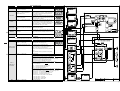
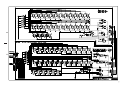
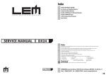
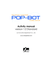
BACHMANN Index & Warnings GENERALMUSIC S.p.A. Sales Division: 47842 S.Giovanni in Marignano (RN) ITALY - Via delle Rose, 12 - tel. 0541/959511 - fax 0541/957404 - http://www.generalmusic.com SERVICE MANUAL Notice Service must be carried out by qualified personnel only. Any tampering carried out by unqualified personnel during the guarantee period will forfeit the right to guarantee. For a correct operation of the instrument, after having switched off, be careful to wait at least 3 seconds before switching on again. To improve the device's specifications, the schematic diagrams may be subject to change without prior notice. Schematic Diagrams Schematic Notes All components marked by this symbol have special safety characteristics, when replacing any of these components use only manufacturer's specified parts. The (µ) micro symbol of capacitance value is substituted by U. The (Ω) omega symbol of resistance value is substituted by E. The electrolytic capacitors are 25Vdc rated voltage unless otherwise specified. All resistors are 1/4W unless otherwise specified. All switches shown in the "OFF" position. All DC voltages measured to ground with a voltmeter 20KOhm/V. CODE : 270208 Soldering point. Supply voltage. Male connector. Logic supply ground. Female connector. Analog supply ground. M/F faston connector. Signal ground. Test point. Chassis ground. ATTENTION Observe precautions when handling electrostatic sensitive devices Flag joined with one or more flags with the same signal name inscribed. 1o 1) To remove the rear panel unscrew the fifteen screws from behind of the instrument. Pull the cover upwards and lift it up. 2) To access the electronics parts turn the front panel locks and pull the panel towards you. To remove the control panel unscrew the four screws from the bottom side. Assembled Parts Optical sensors Left pedal Central pedal Right pedal 1) Key front 2) Key top 19) Hammer "Load" 20) Hammer stop rail 3) Natural, white key 4) Sharp, black key 21) Hammer sto rail felt 22) Hammer center pin 5) Balance rail pin 23) Hammer but spring 6) Bridle wire, tape wire 7) Jack spring 24) Hammer flange 25) Spoon 8) Regulating button 26) Wippen flange 9) Back check wire 10) Regulting rail felt 27) Jack 28) Jack flange 11) Regulating rail 12) Bridle strap, bridle tape 29) Balance rail pin 30) Front rail punching, front washer 13) Back check 31) Front rail pin 14) Back check felt 15) Butt heel leather, back stop leather 32) Contacts Rubber Strip 18 17 Remove all sharp and natural keys to access to the optical sensors, we recommend to dispose the keys in order 16 15 14 13 17) Hammer rest rail 18) Hammer rest felt, hammer rest baize 11 9 1 2 3 5 4 20 21 16) Butt heel, catcher, back stop To access the optical sensor on the pedals board unscrew the two screws and turn it up. 19 6 12 10 8 7 22 23 24 25 26 27 28 29 30 3) To access the speaker box, you must lift the speaker front panel upwards and towards you. o2 A Optical sensors 33 32 A B 34 31 RPT115 AUTOTEST CHART PROCEDURE OPERATIONS Turn the instrument on w hile holding dow n the tw o data buttons. Start Press the " s " button and rotate the SOUND and EDIT knobs. Se le ctors Press the " s " button again and move the volume potentiometer. Press the " s " button again to test the pedals. Pe dals Sinus Te s t M IDI IN & M IDI OUT Autote s t Stop EV ENT DESCRIPTIONS DISPLAY A display message appears: The display w ill show the message ‘rot’ and then tw o numbers separated by a hyphen -: rotating the selectors; the tw o displayed numbers should change f rom 0 to 5 according to their position. The display show s at f irst the message "Pot" f ollow ed by the numbers f rom 0 to 127 corresponding to the trimmer position of the control; rotate the volume control to verif y the correct operation on display The display show s at f irst the message ‘PEd’ f ollow ed by three digits associated to the pedals : move the pedals and the three displayed digits should change accordingly: 0 corresponds to pedal release, F to pedal completely pressed. The Damper pedal should display intermediate values (1,2,3...C,D,E). Press the " s " button again to test the output levels by means of the sinusoidal signal. The signal is emitted to verif y the audio output levels on speaker and auxiliars outputs. Press the " s " button again to test the MIDI interf ace. The display show s at f irst the message ‘Mid’. Connect the MIDI OUT and MIDI IN ports via a MIDI cable to create a MIDI LOOP. If a loop is present, the display w ill show ‘LLL’, if not,‘---’. Press the " s " button. The display show s the message “StP”: 1.6 ATTENTION The fol l owi ng opera ti ons serves to ca l l i bra te the k eyboa rd sensors. If thi s i s not requi red, turn off the i nstrument a t thi s poi nt, otherwi se conti nue a s descri bed bel ow. Note: During the adjustement phase, the instrument does not respond to the keyb oard. Press the " s " button again The display show s the message “A dJ”: Press all sharp and natural keys one a time w ith the descripted precautions: • Play the keys w ith ppp (pianissimo) action. • Release the keys slow ly to avoid any oscillation. • Be sure that the keys is f ully pressed untill the end stroke, but don't apply any extra pressure. • Perf orm previous operations as unif orm as possible f or all keys. • During calibration avoid any vibration to the keyboard. Press the " s " button again. A utotest escape. Wait f or a f ew seconds w hile the instrument momorises permanentely the new ly calibration of the keyboard. Could happen that keys and/or pedals aren't calibrated because: Optical s e ns ors autocalibration 1) optical sensors are dirty (look at the previous page how to access), 2) optical sensors aren't in the right tollerance range, 3) keys and pedals aren't calibrated in the right w ay. If at least one of previous three events come true, you can hear a sequence of tones (having a gap of 0.5sec). The heard tone belongs to the End of key not w ell calibrated. Calibrations 1 tone -> The upper threshold value is too high. and Che ck 2 tones -> The low er threshold value is less. 3 tones -> Insuf f icient threshold span. If pedals aren't w ell calibrated yet, you can hear other three possibles kind of sequence of tones (having a gap of 200msec ) w ith the f ollow ing means: 2 adiacent tones -> The upper threshold value is too high. 3 adiacent tones -> The low er threshold value is less. 4 adiacent tones -> Insuf f icient threshold span. The heard tones ref er to the pedals not w ell calibrated: • C2, C2#, (D2), (D2#) -> Lef t pedal • C4, C4#, (D4), (D4#) -> Central pedal • C6, C6#, (D6), (D6#) -> Right pedal End Press the " s " button again. Re-start the instrument. 500813 DRW M. Palanghi DWG# CKD P. Faccin DISK: 57 PART: 1/1 APP. M. Galanti REV: 24-10-97 PCB# GENERALMUSIC S.p.A. ITALY BLOCK DIAGRAM RPT115 ALL RIGHTS ARE RESERVED, NO COPIES OR REPRODUCE THIS DOCUMENT WITHOUT WRITTEN CONSENT BY GENERALMUSIC. 3o o4 5o o6 7o Spare Parts List (RPT115) Wooden Parts 8E Woofer 550638 Prog EPROM 140351 * 6 Contacts Hor Male Connector 220093 220087 8e 40w Woofer Speaker 8ohm Tweeter Speaker 140877 Jumper For Contacts Strip (p=2.54mm) 140217 140216 * * Horizontal Jack Stereo Slim Socket Horizontal Female 6 Poles Din Socket 171352 Tweeter Support 140212 * Horizontal Female 5 Poles Din Socket Users Manual (RPT115) 100n 250Vac MKP EMI Capacitor Siemens * * 74HC04 Hex Inverter 6N138 Optocoupler * * BC560 TO92 LN Pnp Transistor 1N4148 100mA 75V Signal Diode 710447 Wooden Parts (Black) 271193 020493 261685 261633 * * Front Panel Music Stand 652855 652238 261630 * Rear Bar 261629 261628 * * Leg Revolving Cover 261627 * Right Foot 261626 261625 * * Left Foot Pedals Support 261624 261623 * * Right Lower Column Left Lower Column 261622 * 261621 261619 * * Power Supply Board 730441 Power Supply Board (PCB#310518) 100602 100035 Sockets Box 2 Keys <+ -> Rubber Pad 230527 230524 * * 090194 080103 347360 Gray Knob 171342 * Left Holding Board 340120 150474 Plexiglass Display Screen Black Hole Top 171341 141010 * * Right Holding Board 4 Contacts Vert Female Connector Optical Contacts Assembly 110285 Power Switch 140917 * 2 Contacts Vert Male Connector 720525 Optical Contacts Assembly 140352 140351 * * 9 Contacts Hor Male Connector 6 Contacts Hor Male Connector 810561 141018 * ** Optical Contacts B. (Left Side) (PCB#310574) 20 Contacts Vert Female Connector Brassed Pedals Assembly BL02RN2-R62 EMI Coil For Signal 100uH Switching Coil 720408 Brassed Pedals Assembly 140323 140010 * * 6 Contacts Vert Male Connector 3 Contacts P=10 Vert Terminal Block 141013 140872 ** ** Con V F 10c P=1.27 Mmatch Amp 4 Contatcs Hor Male Connector Keyboard Bar 810168 * Reed Switch Board (PCB#310272) 110304 * Relay 12V / 2 Switch 5A 250V 100919 ** MC33078 Dual LN J-Fet Operational Amp. Keyboard Cover Front Panel Upper Side 770717 500063 * * Connection Cable Mechanical Parts 110119 100919 * * Fuse Clip 10A max (EU) (US) MC33078 Dual LN J-Fet Operat. Amplifier 100626 090153 ** ** 74HC4053 3x2ch Analog Multiplexer BC327 TO92 Pnp Transistor 261618 * Cover 340105 ** Chassis Support 100900 * L4960 5-40V 2.5A Switching Regulator 080900 ** OPTOELECT. REFLEX SENSOR TCRT5000 261615 261614 * * Right Side Left Side 171261 170880 ** ** Chassis Support Screen Panel 100045 100043 * * 7812 +12V 1A Voltage Regulator 7912 -12V 1A Voltage Regulator 810560 141013 * ** Optical Contacts B. (Middle Side) (PCB#310575) Con V F 10c P=1.27 Mmatch Amp 261471 261405 * * Keyboard Support Panel Rear Closer Panel 170875 170874 ** ** Right Pedal Left Pedal 100039 090856 * * STK4151V 2x40W Hybrid Amplifier J176 TO92 P-Channel J-Fet Transistor 140872 100919 ** ** 4 Contatcs Hor Male Connector MC33078 Dual LN J-Fet Operational Amp. 261403 * Rear Speaker Panel 170873 ** Centre Pedal 090183 * Bc550 To92 Ln Npn Transistor 100626 ** 74HC4053 3x2ch Analog Multiplexer 261401 710434 * Cross Bar Wooden Parts (Black hi-gloss) 170777 340500 ** * Pedal Return Spring 3 Pedals Comand Lever 080605 080171 * * KBL02 4A 200V Bridge Rectifier Diode Fe6b 6a 100V Fast Recovery Diode 090153 080900 ** ** BC327 TO92 Pnp Transistor OPTOELECT. REFLEX SENSOR TCRT5000 261564 * Music Stand 340499 * 3 Pedals Carring-out Lever 080156 * 1N4002 1A 100V Rectifier Diode 810559 * Optical Contacts B. (Right Side) (PCB#310576) 261471 261405 * * Keyboard Support Panel Rear Closer Panel 340274 210016 * * Pedal Rubber 1x10mm Adhesive Black Felt (specify mt) 080103 030950 * * 1N4148 100mA 75V Signal Diode 470u 16v 20% Low Esr Vert Electrolytic Cap. 141013 140872 ** ** Con V F 10c P=1.27 Mmatch Amp 4 Contatcs Hor Male Connector 261403 261401 * * Rear Speaker Panel Cross Bar 190181 190178 * * Pedals Clog Permanent Magnet 030880 030721 * * 10000uF 25V Snap-In Electrolytic Capacitor 1000u 25V 20% Vert Electrolytic Capacitor 100919 090153 ** ** MC33078 Dual LN J-Fet Operational Amp. BC327 TO92 Pnp Transistor 261400 * Rear Cross Bar 190015 * Adhesive Rubber Foot 030555 * 4700u 50V 20% Snap-In Electrolytic Cap. 080900 ** OPTOELECT. REFLEX SENSOR TCRT5000 261399 261397 * * Wooden Leg Sliding Cover 171263 070556 * * Pedals Spring 20K Lin (90deg. Stroke) Potentiometer 030486 340075 * * 100u 50V 20% Vert Electrolytic Capacitor Nylon Board Spacer 660579 * Optical Contacts Board Support 261396 * Right Food 110011 * T1A Fuse 5x20mm 261395 261394 * * Left Food Pedals Box Mains Filter Board 110010 110003 * * T2A Fuse 5x20mm T3.15A Fuse 5x20mm 261393 261392 * * Front Panel Right Lower Colomn 767987 230565 Mains Filter Board (PCB#315016/2) * 2.5mH 250V 3A AC Line Filter 261391 * Left Lower Colomn 140010 * 3 Contacts P=10 Vert Terminal Block Keyboard Interface Board 261390 261389 * * Keyboard Bar Keyboard Cover 110113 020493 * * Fuse Clip 5x20mm 6A max 100n 250Vac MKP EMI Capacitor Siemens 761148 141018 Keyboard Interface Board (PCB#310577) * 20 Contacts Vert Female Connector 261387 * Front Panel Upper Side 010545 * 4n7 250Vac 141011 * 6 Contacts Vert Female Connector 261386 261383 * * Cover Right Side 150021 130294 * * Cord Lock Mains Cord (EU) 140918 140874 * * 2 Contacts Hor Male Connector Single In Line Vert Male Strip (specify cont.) 261382 710448 * Left Side Wooden Part (Walnut) * * 4 Contatcs Hor Male Connector ST24W02 Smd 2Kbit Serial Access EEprom 261686 * Front Panel Transformer Assembly 140872 104019 100626 * 74HC4053 3x2ch Analog Multiplexer 261654 261653 * * Music Stand Shutter Rear Panel 730453 340329 Transformer Assembly * Dc-Socket Bush 100619 100610 * * 74HC32 Quad 2-Input Or Gate 74HC245 Octal Bus Transceiver 261652 * Speakers Rear Panel 230130 * 150W 230V Transformer 100066 * LM317 1.2-37V 1.5A Adjustable Regulator 261651 261650 * * Rear Cross Bar Leg 190133 140036 * * Lateroid Insulator For Screw Block Screw Block (specify contacts) 010726 010662 * * 19.2MHz Ceramic Resonator With Cap. 220p 10% 50V X8 Cap Array 261648 261647 * * Slider Cover Right Food 261646 * Left Food CPU & Sound Generator Baord 261645 261644 * * Pedal Box Lower Right Colomn 761147 141018 CPU & Sound Generator Borad (PCB#315093) * 20 Contacts Vert Female Connector Controls & Outputs Assembly 261643 * Lower Left Colomn 141011 * 6 Contacts Vert Female Connector 730965 Controls & Phones Board (PCB#310584) 261642 261641 * * Keyboard Bar Keyboard Cover 141010 140889 * * 4 Contacts Vert Female Connector Dual In Line Vert Male Strip (specify cont.) 730966 140890 * ** Display Boad (PCB#310583) 4 Contacts Hor Male Single-Strip 261639 261638 * * Front Panel Upper Side Cover 140874 140352 * * Single In Line Vert Male Strip (specify cont.) 9 Contacts Hor Male Connector 140529 080717 ** ** Microswitch 12V 50mA 0.25mm HDN1105 7 Segments Display 261635 * Right Side 106001 * MC33078P Smd Dual LN J-Fet Operat.Amp. 080103 ** 1N4148 100mA 75V Signal Diode 261634 261471 * * Left Side Keyboard Support Panel 105006 104022 * * HD6413003F16 Cpu Smd F=16MHz CMOS 32MBIT MASK ROM PRO-WAVE2 230569 141018 * * FL5R200PNT EMI Coil For Signal 20 Contacts Vert Female Connector 261401 * Cross Bar 104021 104020 * * CMOS SERIAL ACCESS 32KBIT (4096X8) HM62256AFP-7T SOP Sram 256K Ta=70nS 140917 140877 * * 2 Contacts Vert Male Connector Jumper For Contacts Strip (p=2.54mm) 104012 * 23C32000G SOP Rom 32Mbit Wave1 140874 * Single In Line Vert Male Strip (specify contacts) * * HM514280AJ SOJ Dram 4M5bit Ta=70nS 74HC04D SOIC Hex Inverter 140873 140217 * * 4 Contacts Vert Male Connector Horizontal Jack Stereo Slim Socket Various o8 220114 550645 140877 IC MICRO H8/329 PROG.<VALIS-O RPT 115> Jumper For Contacts Strip (p=2.54mm) 340159 3M Dual Lock Fastening (Specify mt) 104010 103010 340042 Plastic Handle 103009 * 74HC02D SOIC Quad 2-In Nor Gate 140207 * Horizontal Female Jack Socket Note: 324414 324407 Hinge (666 item) Double Hinge (659 item) 103007 103004 * * 74HC74D SOIC Dual Flip-Flop AD1865R SOP 18bit D/A Converter 110321 090194 * * 2ways 6contacts Rotary Switch BC560 TO92 LN Pnp Transistor Each spare part is single quantity unless otherwise specified. Asterisk prefix explanation: 324405 324400 Hinge (661 item) Hinge (29200 item) 103002 103000 * * 74HC245DW Soic Octal Bus Transceiver 74HC14D Soic Hex Inverter Schmitt Trigger 080103 074699 * * 1N4148 100mA 75V Signal Diode 50Kb C.C. 11mm Horr. Rotary Po Omitted = First level spare part. One asterisk = Second level, part of previous listed first level part. 323069 Transparent Beating Rubber 101501 * 74AC377DW SOIC Octal Dtype Flip Flop Two asterisk 323029 323005 Holding Cover Pole Beating Rubber 090194 090183 * * BC560 TO92 LN Pnp Transistor Bc550 To92 Ln Npn Transistor AUX & MIDI I\O Board Three asterisk = ............ Any request for not above mentioned part must encompass specific description including: 210074 Black Acoustic Cloth 081000 * PMLL4148 Smd 100mA 75V Signal Diode 730683 AUX & MIDI I\O Board (PCB#310551) 1) Model name, 210016 170585 1x10mm Adhesive Black Felt (specify mt) Metal Foot 080241 010727 * * 5V6 1W 5% Zener Diode 45.1584MHz Quartz Resonator 230569 230527 * * FL5R200PNT EMI Coil For Signal BL02RN2-R62 EMI Coil For Signal 2) Section name, 3) Module code, 657241 660405 Black tube Heat Sink Protection Grid 010704 010662 * * 16MHz Quartz Resonator 220p 10% 50V X8 Cap Array 141010 140917 * * 4 Contacts Vert Female Connector 2 Contacts Vert Male Connector 4) Reference name, 5) Quantity number. = Third level, part of previous listed second level part.