1
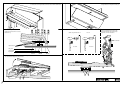
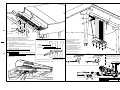
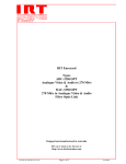
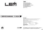
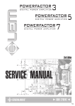
Index & Warnings
SERVICE MANUAL
Schematic Diagrams
GENERALMUSIC S.p.A. Sales Division: 47842 S.Giovanni in Marignano (RN) ITALY - Via delle Rose, 12 - tel. 0541/959511 - fax 0541/957404 - http://www.generalmusic.com
Notice
Service must be carried out by qualified personnel only. Any tampering carried out by unqualified personnel during the guarantee
period will forfeit the right to guarantee.
For a correct operation of the instrument, after having switched off, be careful to wait at least 3 seconds before switching on again.
To improve the device's specifications, the schematic diagrams may be subject to change without prior notice.
Schematic Notes
All components marked by this symbol have special safety characteristics, when replacing any of these components use only
manufacturer's specified parts.
The (µ) micro symbol of capacitance value is substituted by U. The (Ω) omega symbol of resistance value is substituted by E.
The electrolytic capacitors are 25Vdc rated voltage unless otherwise specified. All resistors are 1/4W unless otherwise specified.
All switches shown in the "OFF" position. All DC voltages measured to ground with a voltmeter 20KOhm/V.
Soldering point.
Supply voltage.
Male connector.
Logic supply ground.
Female connector.
Analog supply ground.
M/F faston connector.
Signal ground.
Test point.
Chassis ground.
Flag joined with one or more flags with the same signal name inscribed.
ATTENTION
Observe precautions when handling
electrostatic sensitive devices
1 J
To access to the pedals board you must unlock
and pull the lower front panel towards you.
To access the mechanical parts turn the front panel locks and pull the panel towards you.
To remove the control panel unscrew the four screw from the bottom side.
To access the optical sensor on the
pedals board unscrew the two screws
and turn it up.
Shank stop with silencer on
Let-off
Once removed the keys unscrew the five
screws (B) from the front panel of the
contacts board and unscrew the fourtyeight nuts (A) from the bottom.
Silent bar
Optical sensors
S=7~5mm
L=9~7mm
Left pedal
Central pedal
Right pedal
Remove all sharp and natural keys to access to the optical sensors,
we recommend to dispose the keys in order
A
A
Optical sensors
J 2
A
B
B
G
H
C
A
B
A
B
B
D
F
E
D
Keyboard Interface
Board (Valis)
To access the keyboard’s mechanicals part you have to:
(A) Lift and take away the keyboard’s cover.
(B) Unscrew the two wings-nuts from the bottom.
(C) Take away the two wooden parts from the right and the left
side of the keyboard.
(D) Pull towards you the front keyboard bar.
Now you can access to the Keyboard Intreface Board on the
left side too.
(E) To access to the electronics parts of the control panel
unscrew its four screws.
WARNING: before to take away the keyboard group
mechanicals parts you must:
(F) push the silent bar lever;
(G) unconnect the three connectors from the Valis Interface Board;
(H) push the safety button on the left side.
Now you can pull towards you the keyboard group and access its
machanicals parts.
B
To access the optical sensor on the pedals board unscrew the
two screws and turn it up.
Left pedal
Central pedal
Right pedal
To access the opticals sensors on
the pedals board you have to
dismantle the lyer:
(A) Unconnect the two connectors
from the pedals interface board.
(B) Unscrew without remove the
two hex-head stop screws.
(C) To access the opticals sensors
you must pull the pedals box
downwards and unscrew the eight
screws from its bottom side.
Shank stop with silencer on.
C
Let-off
Once removed the keys unscrew the five
screws (B) from the front panel of the
contacts board and unscrew the fourtyeight nuts (A) from the bottom.
Optical sensors
S=7~5mm
L=9~7mm
Remove all sharp and natural keys to access to the optical sensors,
we recommend to dispose the keys in order
Silent bar
A
Optical sensors
A
B
A
B
500815
DRW M.Palanghi
DWG#
CKD R.Giorgi
DISK: 60 PART: 1/1
APP. M.Galanti
REV: 1/12/97
PCB#
GENERALMUSIC S.p.A. ITALY
NOTTURNO
DUSASSENBLING
INSTRUCTIONS
ALL RIGHTS ARE RESERVED, NO COPIES
OR REPRODUCE THIS DOCUMENT WITHOUT
WRITTEN CONSENT BY GENERALMUSIC.
3 J
rev. 21-04-00
NOTTURNO INITIAL CHECK
Operations Description
Display
The following procedures must be executed subsequently in the specified order.
Before turning on the instrument, check the jumpers setting on CPU & SOUND GENERATOR
BOARD to be corresponding to the model accordingly the following table:
MODEL
J1 J2 J3 J4
GRPT140
NO YES YES 2-3
RPT115
NO YES YES 2-3
RP-PRO1
NO NO NO 1-2
RP-EXPANDER
NO NO YES 1-2
NOTTURNO 126,117,113 YES NO NO 1-2
NOTTURNO 190
YES NO YES 1-2
NOTTURNO Keyboard Automatic Calibration
Operations Description
Display
Start with the instrument in AUTOTEST mode as described above and press data "▲" button
until the display shows "ADJ".
ADJ
Press all the natural and sharp keys respecting the following precautions:
1) One or more keys at the same time is not important but each key once at least.
2) Play the keys slowly with PPP (pianissimo) action as uniform as possible for whole
keyboard extension.
3) Release the keys slowly to avoid any oscillation or vibration.
4) Be sure that all keys are pressed at their end stroke, without apply extra pressure.
5) Press the three pedals also.
ADJ
Pressing "▲" and wait since the instrument memorizes the new calibration.
If you do not hear a note your keyboard is successful calibrated. Press again "▲" and the
instrument will restart in standard operation.
Turn on the instrument.
Check the supply DC
(CN4) between pin9
(CN4) between pin1
(CN4) between pin1
voltages on
and pin6 =
and pin4 =
and pin5 =
CPU & SOUND GENERATOR BOARD:
+5±0,25Vdc
+5±0,25Vdc
-5±0,25Vdc
NOTTURNO AUTOTEST PROCEDURE
Operations Description
Display
The instrument starts in AUTOTEST mode turning on the instrument while pressing down the
data "▲" and "▼" buttons.
NOTE: Each time you press the data "▲", button the autotest procedure skips to the next
step.
During the autotest and auto-calibration procedures the instrument does not respond at any
keyboard action.
AUT
The display shows "rot"; rotating the "SOUND" and "EDIT" knobs the first and last digit
show their position in the range from 0 to 5 each.
ROT
5-0
The display shows "pot"; rotating the "VOLUME" knob the three digits show its position in
the range from 0 to 127.
POT
064
The display shows "ped"; this test must be skipped.
PED
The instrument generates a 1KHz sinusoidal signal in both audio channels, verify with an
oscilloscope the signal at the outputs.
Phones output without load = 3.0±0.5Vpp
AUX output = 1.7±0.3Vpp
The display shows "mid"; connecting MIDI OUT and MIDI IN sockets with a Midi Cable, the
instrument checks the loop showing "LLL" on the display if it is working correctly
or "---" if not.
MID
LLL
The display shows "STP" to confirm the end of Autotest procedure.
Now turn off the instrument if you do not want to calibrate the keyboard.
STP
❏ 4
If the instrument play some notes the calibration is not done properly, the keys not
calibrated are notified in order from higher to lower tones, you may hear:
1 tone for each key note that has upper threshold value too high,
2 tones for each key note that has lower threshold value too low,
3 tones for each key note that has not enough threshold range.
The most frequent reasons are the following, check these in the order specified below:
1) You have not activated one or more keys during the auto-calibration procedure.
Solution: repeat the auto-calibration procedure from beginning.
2) The optical sensors are dirty.
Solution: check these disassembling the keyboard, clean the optical sensors
with a cotton flock slightly soaked with denaturated alcool, reassemble the
keyboard and finally repeat the auto-calibration procedure.
3) The optical sensor are out of the tolerance range.
Solution: disassemble the keyboard and replace on the contacts board the optical
sensor that does not work properly, reassemble the keyboard and check it
repeating the auto-calibration procedure.
Note: Execute a calibration everytime the boards 810559,810560,810451 and 761148 are repaired or replaced and each
time you consider it may be required, such as: keys replacement, keys re-alignament, climatic temperature very hot or
very cold respect the ambient standard temperature of 25°c.
DRW M. Palanghi
DWG# 500816
PCB#
GENERALMUSIC S.p.A. ITALY
CKD P. Faccin
DISK: 60 PRT: 1/1
BLOCKS DIAGRAM NOTTURNO
APP. M. Galanti
REV: 24-10-97
ALL RIGHTS ARE RESERVED, NO COPIES
OR REPRODUCE THIS DOCUMENT WITHOUT
WRITTEN CONSENT BY GENERALMUSIC.
5 J
J 6
7 J
J 8
9 J
Spare Parts List
Accessories
970183
271204
230V AC/DC ADAPTER
User’s Manual
Various
660557
653386
652238
347360
110285
660558
150021
140036
170975
Control Box Chassis
AUX & MIDI I\O Box
2 Keys <+ -> Rubber Pad
Gray/Black Knob
Power Switch
Cover
Cord Lock
Screw Block (specify contacts)
Button to release the Keyboard Mechanicals Parts
Controls & Phones Board
730965
730966
Controls & Phones Board (PCB#310584)
*
Display Boad (PCB#310583)
140890
140529
080717
080103
230569
141018
140917
140877
140874
140873
140217
140207
110321
090194
080103
074699
**
**
**
**
*
*
*
*
*
*
*
*
*
*
*
*
4 Contacts Hor Male Single-Strip
Microswitch 12V 50mA 0.25mm
HDN1105 7 Segments Display
1N4148 100mA 75V Signal Diode
FL5R200PNT EMI Coil For Signal
20 Contacts Vert Female Connector
2 Contacts Vert Male Connector
Jumper For Contacts Strip (p=2.54mm)
Single In Line Vert Male Strip (specify contacts)
4 Contacts Vert Male Connector
Horizontal Jack Stereo Slim Socket
Horizontal Female Jack Socket
2ways 6contacts Rotary Switch
BC560 TO92 LN Pnp Transistor
1N4148 100mA 75V Signal Diode
50Kb C.C. 11mm Horr. Rotary Po
Pedals Optical Contacts Board
810563
141011
140918
080900
Pedals Optical Contacts Board (PCB#310585)
*
6 Contacts Vert Female Connector
*
2 Contacts Hor Male Connector
*
Optoelectronic Reflex Sensor TCRT5000
CPU & Soumd Generator Board
761209
550638
141018
141012
141011
141010
140929
140889
106001
105006
105002
104022
104021
104020
104012
104010
103010
103009
103007
103004
103002
103000
101501
081000
055102
055101
055100
050492
030565
030245
010727
010704
010662
010599
140877
CPU & Soumd Generator Board (PCB#315093)
Program EPROM
*
20 Contacts Vert Female Connector
*
Con V F 8 C P=1.27 Mmatch Amp
*
6 Contacts Vert Female Connector
*
4 Contacts Vert Female Connector
*
9 Contacts Vert Male Connector
*
Dual In Line Vert Male Strip (specify contacts)
*
MC33078P Smd Dual LN J-Fet Operational Amplifier
*
HD6413003F16 Cpu Smd F=16MHz
*
DISP3 Digital Sound Processor
*
32Mbit Sounds Rom Pro-Wave2
*
CMOS SERIAL ACCESS 32KBIT (4096X8)
*
HM62256AFP-7T SOP Sram 256K Ta=70nS
*
32Mbit Sounds Rom Wave1
*
HM514280AJ SOJ Dram 4M5bit Ta=70nS
*
74HC04D SOIC Hex Inverter
*
74HC02D SOIC Quad 2-In Nor Gate
*
74HC74D SOIC Dual Flip-Flop
*
AD1865R SOP 18bit D/A Converter
*
74HC245DW Soic Octal Bus Transceiver
*
74HC14D Soic Hex Inverter Schmitt Trigger
*
74AC377DW SOIC Octal Dtype Flip Flop
*
PMLL4148 Smd 100mA 75V Signal Diode
*
33E X4 1/16w 5% Smd Resistor Array
*
4K7 X4 1/16w 5% Smd Resistor Array
*
100E X4 1/16w 5% Smd Resistor Array
*
10Kx8 1/8w 5% Resistor Array
*
220u 25V 20% Vert Electrolytic Capacitor
*
10u 50V 20% Vert Electrolytic Capacitor
*
45.1584MHz Quartz Resonator
*
16MHz Quartz Resonator
*
220p 10% 50V X8 Cap Array
*
1u 50V -20+80% Ceramic Cap. Multilayer
Jumper For Contacts Strip (p=2.54mm)
Power Supply & Phones Amplifier Board
730972
141010
140929
140917
140873
140351
140211
110305
100962
100919
100901
090183
090153
090152
080241
080170
080156
080103
030805
J 10
Power Supply & Phones Amplifier Board (PCB#310586)
*
4 Contacts Vert Female Connector
*
9 Contacts Vert Male Connector
*
2 Contacts Vert Male Connector
*
4 Contacts Vert Male Connector
*
6 Contacts Hor Male Connector
*
Horizontal Male Dc Socket
*
Relay 12V / 2 Switch 1A 250V
*
TDA 8542 2X1W BTL AUDIO AMPLIFIER
*
MC33078 Dual LN J-Fet Operational Amplifier
*
L4962 5-40V 1.5A Switching Regulator
*
Bc550 To92 Ln Npn Transistor
*
BC327 TO92 Pnp Transistor
*
BC337 TO92 Npn Transistor
*
5V6 1W 5% Zener Diode
*
BYV27 2A 100V Fast Recovery Diode
*
1N4002 1A 100V Rectifier Diode
*
1N4148 100mA 75V Signal Diode
*
2200u 25V 20% Vert Electrolytic Capacitor
AUX & MIDI I\O Board
730683
230569
230527
141010
140917
140351
140217
140216
140212
100602
100035
090194
080103
AUX & MIDI I\O Board (PCB#310551)
*
FL5R200PNT EMI Coil For Signal
*
BL02RN2-R62 EMI Coil For Signal
*
4 Contacts Vert Female Connector
*
2 Contacts Vert Male Connector
*
6 Contacts Hor Male Connector
*
Horizontal Jack Stereo Slim Socket
*
Horizontal Female 6 Poles Din Socket
*
Horizontal Female 5 Poles Din Socket
*
74HC04 Hex Inverter
*
6N138 Optocoupler
*
BC560 TO92 LN Pnp Transistor
*
1N4148 100mA 75V Signal Diode
Optical Contacts Assembly
720525
810561
141018
141013
140872
100919
100626
090153
080900
810560
Optical Contacts Assembly
Optical Contacts Board (Left Side) (PCB#310574)
*
20 Contacts Vert Female Connector
*
Con V F 10c P=1.27 Mmatch Amp
*
4 Contatcs Hor Male Connector
*
MC33078 Dual LN J-Fet Operational Amplifier
*
74HC4053 3x2ch Analog Multiplexer
*
BC327 TO92 Pnp Transistor
*
OPTOELECTRONIC REFLEX SENSOR TCRT5000
Optical Contacts Board (Middle Side) (PCB#310575)
141013
140872
100919
100626
090153
080900
810559
*
Con V F 10c P=1.27 Mmatch Amp
*
4 Contatcs Hor Male Connector
*
MC33078 Dual LN J-Fet Operational Amplifier
*
74HC4053 3x2ch Analog Multiplexer
*
BC327 TO92 Pnp Transistor
*
OPTOELECTRONIC REFLEX SENSOR TCRT5000
Optical Contacts Board (Right Side) (PCB#310576)
141013
140872
100919
090153
080900
660579
*
Con V F 10c P=1.27 Mmatch Amp
*
4 Contatcs Hor Male Connector
*
MC33078 Dual LN J-Fet Operational Amplifier
*
BC327 TO92 Pnp Transistor
*
OPTOELECTRONIC REFLEX SENSOR TCRT5000
Optical Contacts Board Support
Keyboard Interface Board
761148
141018
141011
140918
140874
140872
104019
100626
100619
100610
100066
010726
010662
550645
140877
Keyboard Interface Board (PCB#310577)
*
20 Contacts Vert Female Connector
*
6 Contacts Vert Female Connector
*
2 Contacts Hor Male Connector
*
Single In Line Vert Male Strip (specify contacts)
*
4 Contatcs Hor Male Connector
*
ST24W02 Smd 2Kbit Serial Access EEprom
*
74HC4053 3x2ch Analog Multiplexer
*
74HC32 Quad 2-Input Or Gate
*
74HC245 Octal Bus Transceiver
*
LM317 1.2-37V 1.5A Adjustable Regulator
*
19.2MHz Ceramic Resonator With Capacitors
*
220p 10% 50V X8 Cap Array
IC MICRO H8/329 PROG.<VALIS-O RPT 115> 100746
Jumper For Contacts Strip (p=2.54mm)
Note:
Each spare part is single quantity unless otherwise specified.
Asterisk prefix explanation:
Omitted
= First level spare part.
One asterisk = Second level, part of previous listed first level part.
Two asterisk = Third level, part of previous listed second level part.
Three asterisk = ............
Any request for not above mentioned part must encompass specific description including:
1) Model name,
2) Section name,
3) Module code,
4) Reference name,
5) Quantity number.