1
USM-0002
Issue: D
User Manual: FleXible Electronic Power System:
CS-XUEPS2-41/-42
Date: 26/02/2015
Page: 25 of 44
5B, Skypark 5, 45 Finnieston
Street, Glasgow, G3 8JU
Care should be taken to ensure that the switches used are rated to the appropriate
current levels.
Please contact Clyde Space for information on implementing alternative switch or dummy
load configurations.
8.9 Battery connection
1
4
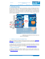
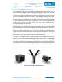
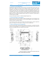
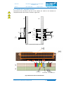
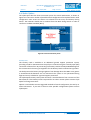
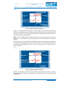
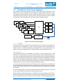
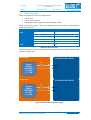
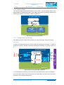
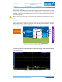
Connection of the battery systems on the FleXU EPS is via the Cubesat kit bus. Ensure that
the pins are aligned, and located in the correct position, as any offset can cause the
battery to be shorted to ground, leading to catastrophic failure of the battery and damage
to the EPS. Failure to observe these precautions will result in the voiding of any warranty.
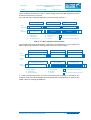
When the battery is connected to the EPS, the battery will be fully isolated until
implementing and connecting a switch configuration, as discussed in Section 8.8. Ensure
that the battery is fully isolated during periods of extended storage.
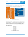
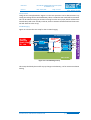
When a battery board is connected to the CubeSat Kit header, there are live, unprotected
battery pins accessible (H2.33-34). These pins should not be routed to any connections
other than the switches and Clyde Space EPS, otherwise all protections will be bypassed
and significant battery damage can be sustained.
8.10
Buses
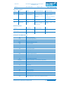
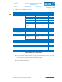
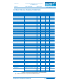
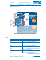
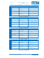
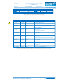
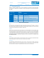
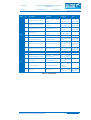
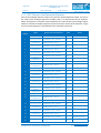
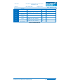
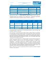
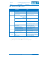
All power buses are accessible via the CubeSat Kit headers and are listed and described in
Table 8-8. These are the only power connections that should be used by the platform
since they follow all battery and bus over-current protections.
All I2C communications can are accessible via the CubeSat kit header. See Section 11.
SOLUTIONS FOR A NEW AGE IN SPACE
PROPRIETARY & CONFIDENTIAL INFORMATION
www.clyde-space.com
© Clyde Space Limited 2015