1
USM-0002
User Manual: FleXible Electronic Power System:
CS-XUEPS2-41/-42
Issue: D
Date: 26/02/2015
5B, Skypark 5, 45 Finnieston
Street, Glasgow, G3 8JU
Page: 37 of 44
12. TEST
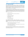
All EPS are fully tested prior to shipping, and test reports are supplied. In order to verify
the operation of the EPS please use the following outlined instructions.
Step by step intro of how to connect and verify operation:
In order to test the functionality of the EPS you will require:
•
•
•
•
•
•
•
•
EPS
Battery (or simulated battery)
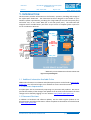
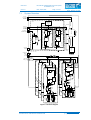
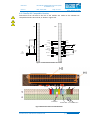
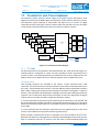
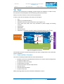
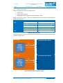
Breakout Connector (with connections as per Figure 12-1)
Array Input (test panel, solar array simulator or power supply and limiting
resistor)
Oscilloscope
Multimeter
Electronic Load
Aardvark I2C connector (or other means of communicating on the I2C bus)
CLYDE SPACE 3U EPS
Array Input
+
-
SAx.2
BCR_OUT
H2.41-44
SEPARATION
SWITCH
H2.45
-46
N/C
H2.35-36
PCM_IN
BCRx
5V
DUMMY_LOAD
H2.37-38
PULL PIN
H2.33-34
3.3V
BATT_POS
H2.25
-26
H2.27
-28
ELECTRONIC LOAD
SAx.1
BATTERY
Figure 12-1 Suggested Test Setup
The breakout connector should be wired with the switch configuration to be used under
mission conditions.
12.1
Power up/Down Procedure
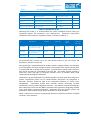
The order of assembly should follow the order detailed below:
•
•
•
•
•
•
•
Breakout connector assembled with switches set to launch vehicle configuration
(as shown in Figure 12-1)
Fit Breakout connector to EPS
Connect battery to stack
Connect electronic load (no load) to buses
Remove Pull Pin
Activate Separation Switch
Connect array input
When powering down this process should be followed in reverse.
SOLUTIONS FOR A NEW AGE IN SPACE
PROPRIETARY & CONFIDENTIAL INFORMATION
www.clyde-space.com
© Clyde Space Limited 2015