1
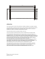
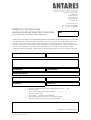
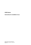
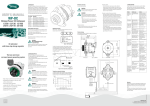
Compact Power Inverters 12V & 24V VERSIONS
Instructions for
installation and use
© 2004
Battery Equaliser
CE MARKING – INFORMATION
UNPACKING
APPLICATION
IMPORTANT SAFETY INFORMATION
INSTALLATION
OPERATION
TROUBLESHOOTING
FM 37786
ISO 9001:2000
OUTLINE SPECIFICATIONS
Antares (Europe) Limited
Chiltern Hill . Chalfont St Peter
Gerrards Cross . Bucks . SL9 9UQ . UK
Tel: +44 (0) 1753 890888
Fax: +44 (0) 1753 891260email:[email protected]
web site: http://www.antares.co.uk
WARRANTY
SERVICE
WARRANTY RETURN FORM
Compact Power Inverters User Manual Manual No 13050_3
CE MARKING - INFORMATION
Conditions of use for which CE mark applies
This equipment is intended to be used solely for professional purposes in commercial and light
industrial locations
Non approved conditions of use
This unit may be suitable for use in other applications, but it can only be supplied as a
component in this respect, for which the CE mark displayed on this manual does not apply. If
the unit is used in this way, as a component part to build a battery charging or similar
apparatus, then this unit is supplied solely on the condition that it is the responsibility of the
manufacturer of the charging apparatus to ensure that the apparatus complies with the
requirements of the relevant legislation, and apply the CE marking should it be required. In this
case, this user manual does not apply, and reference should be made to Antares (Europe)
Limited for any information required for compliance with the legislation.
UNPACKING
Pack contents:
1 Antares Compact Power Inverter
1 Instructions for Installation and Use
APPLICATION
The Compact Power Inverter (CPI) is suitable for a powering a wide range of electrical
appliances and equipment on vehicles or in fixed locations. High surge capacity, coupled with
fully regulated output voltage and crystal controlled output frequency allow equipment,
traditionally difficult to operate from inverters to be successfully run, without any reduction in
performance. Such equipment includes microwave cookers, flourescent and tungsten lighting
systems, refrigeration plant, audio-visual entertainment products, computers and computer
peripherals. Note that power factor correction capacitors fitted to some flourescent lamps
serve no useful purpose when run from the CPI, and can be advantageously disconnected to
improve the inverter’s efficiency.
It is important that the inverter and its supporting battery system are properly sized for the task
in hand. The start up power demanded by some appliances can be troublesome if not taken
into account. Several tens of kilowatts surge power can be drawn from the commercial mains
supply, but this is not always practical with an inverter when using a battery as the power
source.
IMPORTANT SAFETY INFORMATION
1. Please read and observe the installation instructions, which contain further safety
information.
2. DC Input - It is essential that correctly sized input leads are fitted. Some guidance is given
on page 4. The unit rating plate provides information on the DC input current.
3. AC Output - The AC output from the inverter must be treated as equivalent to normal
mains, and wired in accordance with the appropriate regulations for mains circuits.
4. Protective Earthing Arrangements
In order to reduce the AC output terminal touch voltage, the inverter output is centre tap
referenced to the output earth conductor. The earth conductor is in turn, internally connected
to the inverter case metalwork. Note that the CPI embodies an electronic residual current trip
for additional user protection.
1
Compact Power Inverters User Manual
Manual No 13050_3
INSTALLATION
Choosing a location
Choose a location where the unit will not be subjected to water spray, dust, or insect ingress.
Filters are available for the fan air intake, and must be fitted if a low dust environment cannot
be provided. Locations subjected to high temperature or vibration must be avoided if
performance and reliability are not to be impaired. The inverter may be mounted in any
orientation, but ensure that there is sufficient clearance at each end of the unit to allow air to
enter and leave without undue restriction (15 to 20mm clearance is sufficient). Any possibility
of the air vents becoming obstructed accidentally should be prevented. Ideally, the unit should
be located in the same area as the battery in order to minimise voltage drop in the DC input
leads.
Connections
DC INPUT - Two DC input studs, size M8, are provided on the rear of the unit with an
adjacent label showing polarity and nominal input voltage. Cables should be run directly from
the inverter studs to the DC power source; normally a battery. In order to minimise feed
voltage drop, it is essential to use cables capable of handling the high current drawn (See
rating plate). If the voltage drop is excessive, the inverter low voltage cut-off may operate
prematurely. The table on the next page gives recommended minimum cable sizes for typical
installations, based on a 2% voltage drop at full load:
AC OUTPUT - Two sockets are provided for connection of the load equipment. The output
may be routed directly to the equipment to be operated. External protection devices are not
necessary, as the inverter electronically protects against overload and earth fault conditions.
Model
90041
Length of cable run from inverter to battery
1m
2m
3m
5m
10m
70mm2
70mm2
2x50mm2 2x70mm2 4x70mm2
25mm2
25mm2
35mm2
90042
90048
90049
90044
50mm2
2x50mm2
90045
90051
90052
Mounting
Integral flanges are provided for ease of mounting in situations where the unit needs to be
secured to prevent movement, such as in vehicles. Ideally, the mounting should make
electrical contact with the vehicle bodywork. Mounting hole locations are shown in the centre
pages of this manual.
2
Compact Power Inverters User Manual
Manual No 13050_3
12.0
375.0
12.0
386.0
30.0
135.0
195.0
30.0
130150-1
OPERATION
The Compact Power Inverter is fully automatic in operation making it very simple to operate.
The On/Off switch is used to turn the inverter on and off, and acts to fully isolate the unit from
the DC input. External contactors are not necessary. NB: A remote switch connection is
available as an option, and should be specified when ordering.
Three panel lamps show the operating condition of the unit:
The green OUTPUT lamp illuminates when power is available from the output sockets.
The red OVERLOAD lamp illuminates if the inverter’s load is in excess of its rating, or if
overheating occurs. The lamp will ’cycle’ if a marginal overload condition exists, as the unit
attempts to start the load. The lamp will remain on if a gross overload condition exists such as
a short circuit and the power will be cut. Note that in some instances overload can occur due
to an extremely poor power factor load, even though the power rating appears sufficient.
Recovery is automatic, once the offending fault condition is removed.
The red PROTECTION lamp illuminates together with the OVERLOAD lamp if an external
fault condition exists, putting the inverter into protection mode. Input overvoltage or
undervoltage, or activation of the inverter’s earth leakage trip will cause this to happen. The
earth leakage trip can be reset by switching off, then switching back on again.
The Compact Power Inverter may be connected permanently to the battery. The unit is
comprehensively protected from abuse or fault conditions. In vehicular applications, the
engine may be started and run with the Compact Power Inverter connected.
The Compact Power Inverter provides fully regulated Quasi Sine wave AC output.
3
Compact Power Inverters User Manual
Manual No 13050_3
TROUBLESHOOTING
The Antares inverter is an advanced unit, designed to closely mimic the mains AC supply. It
does however have some limitations which in some circumstances may cause loads to
operate incorrectly. The front panel lamps; OUTPUT, OVERLOAD, PROTECTION may be used
to aid diagnosis of operational problems. The function of these lamps is described above.
Problems can arise with high start surge loads, such as electric motors, because of the
inability of the battery system to provide the required surge power. This could be due to battery
sizing, or low state of charge. In this situation, the overload & protection lamps illuminate as
the battery voltage collapses. The inverter then shuts off momentarily allowing the battery to
recover, the lamps extinguish, and the cycle repeats. Larger batteries or an improved charing
regime are required to alleviate this problem. A similar problem can arise if the voltage drop in
the DC input leads is excessive, causing the inverter undervoltage shut off to operate.
Whatever the problem, Antares technical support will be pleased to help diagnose & resolve
any problems that may arise. Please call if help is required.
OUTLINE SPECIFICATIONS
See ratings plate for your particular model;
Output Power:
800W, 2200W (800VA, 2200VA)
Frequency:
50Hz, 60Hz, or 400Hz
Output Voltage:
230VAC, 110VAC +/- 5% over range
Output Type:
Regulated Quasi Sine
Output Sockets:
BS 4343 standard, BS 1363 optional
O
Environment:
-10 to +45 C, 0 to 95% RH
Protection:
Output overload protection
Input overvoltage protection
Input undervoltage protection
Input reverse polarity protection
Thermal trip
Earth Leakage trip (Cycle on-off switch to reset)
With the exception of the earth leakage trip, all protection
mechanisms automatically recover when the offending condition is
removed.
Features:
Speed-controlled fan cooling
Soft Start
Internal Battery Isolator
Remote control (Optional)
WARRANTY
The Compact Power Inverter comes with a full parts and labour ‘return to base’ warranty, held
for two years from the date of invoice from Antares (Europe) Limited. In the event of any
problem, please telephone first in order to confirm that the problem lies with the unit, and
obtain a returns authorisation reference. Units will normally be repaired or replaced, and
shipped within 24 hours of receipt, subject to availability of parts. Full details of the warranty
provisions are contained in our ‘Terms & Conditions of Sale’
4
Compact Power Inverters User Manual
Manual No 13050_3
SERVICE
Units not covered by warranty or maintenance contracts may be returned for repair, for which
a charge will be made. In the event of any problem, please telephone first in order to confirm
that the problem lies with the unit, and obtain a returns authorisation reference. Units will
normally be repaired or replaced with a unit of similar age and condition, and shipped back
within 24 hours of receipt, subject to availability of parts. Repaired units carry a further 1 year
warranty on parts and labour.
Alternatively, spares may be purchased for repair by customers, but no warranty can be given
in respect of the consequences of incorrect diagnoses.
This manual is applicable to the following products:
CODE
DESCRIPTION
RATING
90041
Inverter
12V/1600W/230VAC
90048
Inverter
12V/1600W/110VAC
90042
Inverter
12V/2200W/230VAC
90049
Inverter
12V/2200W/110VAC
90044
Inverter
24V/1600W/230VAC
90051
Inverter
24V/1600W/110VAC
90045
Inverter
24V/2200W/230VAC
90052
Inverter
24V/2200W/110VAC
12V Versions
24V Versions
© 2001 Antares (Europe) Limited
Chiltern Hill, Chalfont St Peter, Gerrards Cross, Bucks. SL9 9UQ
Tel: 01753 890888
Fax: 01753 891260
e-mail: [email protected]
web site: http://www.antares.co.uk
5
Compact Power Inverters User Manual
Manual No 13050_3
Antares (Europe) Limited
Chiltern Hill
Chalfont St Peter
Gerrards Cross
Buckinghamshire
SL9 9UQ UK
www.antares.co.uk
Tel: +44 (0) 1753 890888
Fax: +44 (0) 1753 891260
❑ PRODUCT RETURNS FORM M
❑ ADVANCE REPLACEMENT RETURNS FORM
Date
(TICK BOX ABOVE TO INDICATE TYPE OF RETURN)
PLEASE USE THIS FORM TO ACCOMPANY RETURNS TO ANTARES (EUROPE) LIMITED. This will enable
us to expedite your repair/return more efficiently. If you have your own return form, please attach it to
this form. After receipt of your return we will either repair or replace the unit if within our warranty. If
outside our warranty, we will provide a written quotation for repair/replacement. Please note that in the
case of a ‘no fault found’ or the repair does not proceed, then a charge of £25 ex VAT and return
carriage (if required) is payable. Goods arriving without suitable paperwork will take longer to process.
Contact
Company Name
Delivery Address (for return)
Part Number
Serial Number
Product Description
Vehicle Type
Registration/your reference
Contact Fax
Contact Tel
Reason for return
(
(
(
(
(
(
(
)
)
)
)
)
)
)
Advance replacement returned for credit against invoice ..… RA ………
Incorrect supply
Please repair under warranty (Invoice date ……/……/……)
Please quote for repair
Please repair – purchase order attached ( )
Not required (note there may be a restocking charge)
Unit for reconditioning (advance replacement RA# ………………)
Description of observed fault and additional relevant information
continued on separate page ( )
Form 040 Issue 8 26.07.04