1
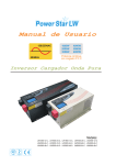
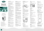
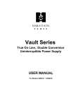
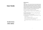
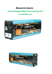
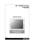
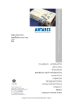
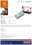
This manual is important instruction that you should follow
during installation and maintenance of the inverter. Please
read all instructions before operating the equipment and save
this manual for future reference.
SIMTEK POWER SERVICES
Sunset Lane 2,Phase 2 (ext),
DHA,Karachi.
021-35386004
021-35394140
0322-2572227
0332-2572227
0345-2215071
1. PRODUCTS SKETCH MAP
2. EP SERIES BASIC WIRING
3. LINE MODE SPECIFICATION
4. INVERTER MODE SPECIFICATION
2
4
5
5. CHARGE MODE SPECIFICATION
6
6. CHARGE MODE SPECIFICATION
7
7. DISPLAY & CONTROL
8
8. GENERAL SPECIFICATION
9. APPENDIX
www.simtek.com.pk
1
10
11
User's manual
User's manual
1. PRODUCTS SKETCH MAP
2. EP SERIES BASIC WIRING
Warning:High voltage,do not open
unless qualified to do so;
Please read instructions
before working on this
product.
Figure 1 top view
fuse
Main domestic battery bank ( 12V )
Figure 2 side view
Battery
Battery
Positive
Negative
CHARGER INPUT
PROTECTION
DC24V
fuse
Remote Control
INVERTER OUTPUT
PROTECTION
Earth
OUTPUT
L
N
INPUT
Figure 3 DC side
1
N
L
OUTPUT
Main domestic battery bank ( 24V )
Figure 4 AC side
www.simtek.com.pk
2
User's manual
User's manual
3. LINE MODE SPECIFICATION
MODEL
Input Voltage Waveform
Sinusoidal(utility or generator)
Nominal lnput Voltage
230Vac
Low Line Disconnect
180Vac±4%
Low Line Re-connect
190Vac±4%
High Line Disconnect
265Vac± 4%
High Line Re-connect
255Vac±4%
Nominal lnput Frequency
Main domestic battery bank ( 48V )
EP-1012 EP-2012 EP-2024 EP-3024 EP-4048 EP-5048 EP-6048
50Hz/60Hz (Auto detection)
Low Line Frequency
Re-connect
58±0.3Hz for 60Hz;
45±0.3Hz for 50Hz;
Low Line Frequency
Disconnect
57±0.3Hz for 60Hz;
45±0.3Hz for 50Hz;
High Line Frequency
Re-connect
64±0.3Hz for 60Hz;
54±0.3Hz for 50Hz;
High Line Frequency
Disconnect
65±0.3Hz for 60Hz;
55±0.3Hz for 50Hz;
2
WHAT CABLE TO USE in mm :
Battery
Earthing
Battery
Positive
Negative
Remote Control
DC24V
Earth
Boat’s earth or bonding
system or vehicle chassis
INVERTER OUTPUT
PROTECT
L
N
INPUT
3
180-330 A
70mm2
N
L
OUTPUT
cable run distance
1.5-4.0m
70 mm2
90mm2
Please note that if there is a problem obtaining for example
90 mm2 cable,use 2*50mm2,or 3*35mm2,One cable is always
best but,cables simply copper and all you require is the copper,
so it does not matter if it is one cable or 10 cables as long as
the square area adds up.Performance of any product can
be improved by thicker cable and shorter runs,so please
round up and keep the length as short as possible.
AC I/O Connection
Remove cover plate
CHARGER INPUT
PROTECT
OUTPUT
125-180A
cable run distance
0-1.5m
50 mm2
A charger or inverter
AC
Power in
Input
Output
E L N N L E
Output Voltage Waveform
As same as lnput Waveform
Over-Load Protection
(SMPS load)
Circuit breaker
Output Short Circuit
Protection
Circuit breaker
Efficiency(Line Mode)
>95%
Transfer Time(AC to DC)
≤10ms(typical)
Transfer Time(DC to AC)
≤10ms(typical)
++++++
++++++
AC
Power out
www.simtek.com.pk
4
User's manual
User's manual
4. INVERTER MODE SPECIFICATION
MODEL
5. CHARGE MODE SPECIFICATION
HV MODEL
EP-1012 EP-2012 EP-2024 EP-3024 EP-4048 EP-5048 EP-6048
HV MODEL
MODEL
EP-1012 EP-2012 EP-2024 EP-3024 EP-4048 EP-5048 EP-6048
Sine wave
Output Voltage Waveform
Nominal Input Voltage
Rated Output Power(VA)
1000
2000
3000
4000
5000
6000
Rated Output Power(W)
1000
2000
3000
4000
5000
6000
230Vac
Input Voltage Range
180-250Vac
According to the battery type
Power Factor
0~1.0
Nominal Output Voltage
Nominal Output Voltage(V)
230Vac
Nominal Charge Current
45A(Max.)
Nominal Output Frequency(Hz)
50Hz±0.3Hz
Charge Current Regulation
±5Adc
Auto tracking Main Frequency(Hz)
Yes(Following Main first connection)
50Hz@45-54Hz
60Hz@55-64Hz
±10%rms
Output Voltage Regulation
Nominal Efficiency
Over-Load Protection
(SMPS load)
Surge rating (10s)
Over Charge Protection
(100%<load<120%)± 10%:Fault (shutdown output)after 2 minutes;
(120%<load<140%)±10% :Fault (shutdown output)after 1 minutes,
Load>140%±10%:Fault (shutdown output)after 20s
3000VA
6000VA
1 HP
9000VA 12000VA 15000VA 18000VA
2 HP
2 HP
3 HP
Circuit breaker
Input:10A
Output:7A
Input:15A
Output:10A
Input:30A Input:35A Input:35A Input:40A
Output:15A Output:20A Output:25A Output:30A
Bat.V≥15.7Vdc/31.4Vdc/62.8Vdc,beeps 0.5s every 1s &fault after 60s
Charge Algorithm
Algorithm
3 HP
Three stage:
Boost CC (Constant current stage)
Float(constant voltage stage)
Boost CV(constant voltage stage)
Current limit (Fault after 10s)
Output Short Circuit Protection
Nominal DC lnput Voltage
Breaker Size
>80%
Capable of starting electric motor 0.5 HP
Inverter Breaker Size
Charger Short Circuit
Protection
Input:10A
Output:7A
12V
Input:15A
Output:10A
12V
24V
Min DC Start Voltage
Input:30A Input:35A Input:35A Input:40A
Output:15A Output:20A Output:25A Output:30A
24V
48V
48V
48V
10V/20V/40V
Low Battery Alarm
10.5Vdc±0.3Vdc for 12V battery
21.0Vdc±0.6Vdc for 24V battery
42.0Vdc±0.6Vdc for 48V battery
Low DC lnput Shut-down
10.0Vdc±0.3Vdc for 12V battery
20.0Vdc±0.6Vdc for 24V battery
40.0Vdc±0.6Vdc for 48V battery
High DC lnput Alarm &Fault
16Vdc±0.3Vdc for 12V battery
32Vdc±0.6Vdc for 24V battery
64Vdc±0.6Vdc for 48V battery
High DC lnput Recovery
15.5Vdc±0.3Vdc for 12V battery
31.0Vdc±0.6Vdc for 24V battery
62.0Vdc±0.6Vdc for 48V battery
Power saver
5
<
Load 25W(Enabled
=
on“P/S auto”setting of Remote control)
www.simtek.com.pk
6
User's manual
User's manual
7.DISPLAY & CONTROL
6. CHARGE MODE SPECIFICATION
①
②
③
ENTER
OPERATING STATUS DISPLAY
Boost CC Stage:If A/C input is applied,the charger will run at full
currentin CC mode until the charger reaches the boost voltage.
Boost CV Stage: In this stage,the charger will keep the boost voltage
in Boost CV mode.The charging current will reduce,until less than 2A,
then drop the voltage down to the float voltage.
Float Stage:In float mode,the voltage will stay at the float voltage.
If the A/C is reconnected or the battery voltage drops below 12Vdc/
24Vdc/48Vdc,the charger wil reset the cycle above.
Charge Stage
Transition Definitions
15
14.5
14
13.5
13
12.5
12
11.5
11
10.5
3
1
2
FLOAT 13.6V
1
2
3
0
1
2
3
4
5
6
7
8
9
4
4
TIME
3
⑥
④
CHR/CRT
4
CHR/MOD
To be used by
factory for set up
Gel USA
AGM 1
AGM 2
Sealed lead acid
Gel EURO
Open lead acid
Calcuim
De sulphation
Not used
Item Indication
24V
48V
12V
24V
48V
14.0
14.1
14.6
14.4
14.4
14.8
15.1
15.5
28.0
28.2
29.2
28.8
28.8
29.6
30.2
31.0
56.0
56.4
58.4
57.6
57.6
58.2
60.4
62.0
13.7
27.4
54.84
13.4
26.8
53.6
13.7
27.4
54.8
13.6
27.2
54.4
13.8
27.6
55.2
13.3
26.6
53.2
13.6
27.2
54.4
4 hours then off
www.simtek.com.pk
11 12 13
Description
①
Display of input voltage When the inverter is turned on,the LCD display shows input voltage,the input
and input frequency
frequency of the display can be changed by switching the button.
②
Working Status of
INVERTER
③
Display of output voltage When the inverter is turned on, the display shows the real output voltage.
④
Display of the Max.charging
current and charging mode
⑤
When the inverter is turned on ,the display shows the real battery voltage.
Display of the battery
When the inverter is low battery,the buzzer beeps 0.5secs in every 5 secs,
voltage
the display flashes and shows" LOW "with the beep.
⑥
Display of load
percentage
The display shows the load percentage. When the inverter is overload, the buzzer
beeps 0.5secs in every 1 sec, the display flashes and shows " OVER" with the beep.
When the load is 100%-120%, the inverter will shut down after 2 minutes' alarm.
When the load is 120%-140%, the inverter will shut down after 1 minute's alarm.
When the load is >140%, the inverter will shut down after 20 secs alarm.
⑦
Display of
Temperature
The display shows the current temperature of the heat sink. When the temperature
is ≥100℃, the buzzer will beep 0.5 secs in every 1 minute, the display will flashes
and show " HIGH" with the beep. When the temperature is ≥105℃, the inverter
will shut down for self-protection.
⑧
The fan is running
⑨
Silence function
The fan logo indicating inverter's fan is running.
It shows the inverter is not in the silence mode. The silence function is inactive
when it is low battery, over load and over temperature.
⑩
The battery is disabled
It shows the battery is disabled, it needs to replace the battery.
11
Warning
When the battery is over voltage, the buzzer beeps 0.5 secs every 1 second, the
display flashes with the beep.
12
Power saver mode
It shows the “Power saver mode" is working. The inveter shut down the output
automatically when in the battery mode and without any load, inverter automaticly
has output when load is more then 40w.
13
Auto re-start
It shows the inverter will be start when AC is connected.
Voltage
12V
⑦
Instruction of the LCD display
Float
Voltage
Description
C
H
A
100 R
G
E
R
%
50 C
U
R
R
E
0
N
T
STEP 2=ABSORPTTON CHARGE AT 14.4V
STEP 4=LOW VOLTAE RESET TO STEP 1
Boost
Switch
setting
7
⑤
5
STEP 1=CONSTANT CURRENT CHARGE
STEP 3=FLOAT VOLTAGE AT 13.6 VOLTS
BATTERY TYPE SELECTOR
2
ON/MUTI
⑧⑨ ⑩
FOR 24 VOLTS
x2
V
O
L
T
S
Battery Type Setting
1
SAVE/GRN
It shows the working status of the inverter. It shows "BYPASS"when the inverter
is in AC mode. It shows "INVERTER" when it is in the battery mode. It shows
"AVR" when it is in the "Boost Voltage" or " Buck Voltage" mode.
The inverter shows the Max.charging current when it is in the AC mode, It will
shows the charging mode by switching the button.
8
User's manual
User's manual
Function of the button
Description
Item Function of the button
8. GENERAL SPECIFICATION
1
Enter button
“OK” button for confirming the Max. Charging current or the charging
voltage mode .
2
Green mode button
When the inverter is working, the "Green mode button" can be opened
or closed by short pressing on the button.
Safety Certification
CE(EN62040-1)
Start / silence function/
input frequency
The inverter can be turned on or turned off by pressing the button for 3
secs. In battery mode, the " silence function" can be ON/OFF by shortly
pressing the button. In AC mode, The input frequency will be displied by
shortly pressing the button.
EMC Classification
En62040 - 2,C2
3
4
5
When the AC is normal, shortly press the button, the display will
keep flashing of "The maximum charging current value". Press
"ENTER” button for confirming this setting. If you did not press
"ENTER" button within 5 seconds, it will automatically return to the
original setting of "maximum charging current value."
Choosing the charging When the AC is normal, shortly press the button, the display will
keep flashing of "The charging voltage" for different tye of batteries.
voltage mode
Press "ENTER” button for confirming this setting.If you did not press
"ENTER" button within 5 seconds, it will automatically return to the
original setting of "charging voltage".
Choosing the Max.
Charging current
Fault recovery
By restart the machine
Operating Temperature
0℃ to 40℃
Range
Storage temperature
-15℃ ~ 60℃
Operatio humidity
5% to 95%
Audible Noise
60dB max
Cooling
Forced air,variable speed fan
Size
EP-1012,EP-2012,EP-2024,EP-3024:461mm*217mm*178mm
EP-4048, EP-6048:636mm*217mm*179**mm
FAN Operation
Variable speed fan operation is required in invert and charge mode. This is
to be implemented in such a way as to ensure high reliability and safe unit
and component operating temperatures in an operating ambient temperature
up to 50℃.
Speed to be controlled in a smooth manner as a function of internal
temperature and/or current.
Fan should not start/stop suddenly.
Fan should run at minimum speed needed to cool unit.
Fan noise level target < 60db.
Fan Operation
The fan logic as below:
Condition
Enter condition
Leave condition
Speed
T≤60℃
T>65℃
OFF
T≤60℃ or T≥80℃
50%
T≤80℃
100%
T≤15%
T≥20%
OFF
20%<T≤50%
T≤15% or T≥50%
HEAT SINK
TEMPERATURE 65℃≤T<85℃
T>85℃
Charge
Current
T>50%
T≤40%
50%
100%
Load≥30%
Load<30%
OFF
Load%
30%≤Load<50%
Load≤20%
or
Load≥50%
50%
(lnvert mode)
Load≥50%
9
Load≤40%
100%
10
User's manual
9. APPENDIX
1.Indicator and Buzzer setting.
Status
Item
Buzzer
CC
Line Mode
CV
Float
Invert Mode
Inverter on
Power saver
Battery Low
Battery High
Alarm Mode
Overload on invert mode
Refer to"Instruction of the LCD display"
beep 0.5s every 1s
OverTemp on line mode
beep 0.5s every 1s
Fan lock
Battery High
Inverter mode overload
OverTemp
Over charge
Back Feed Short
11
beep 0.5s every 1s
OverTemp on invert mode
Over charge
Fault Mode
beep 0.5s every 5s
beep 0.5s every 1s
beep continuous
beep continuous
beep continuous
beep continuous
beep continuous
beep continuous
www.simtek.com.pk
SIMTEK POWER SERVICES
Sunset Lane 2,Phase 2 (ext),
DHA,Karachi.
021-35386004
021-35394140
0322-2572227
0332-2572227
0345-2215071