1
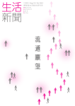
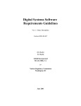
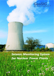
Proceedings of the Korean Nuclear Spring Meeting
Gyeong ju, Korea, May 2003
Unavailability Analysis of Digital Engineered Safety Feature Actuation System
Hyun Gook Kang*, Sudarno Wiharjo**, Seung-Cheol Jang*
* Korea Atomic Energy Research Institute, P.O Box 105, Yuseong, Daejeon, 305-600
[email protected]
** National Nuclear Agency-BATAN, Gedung 80, Serpong, Tangerang 15310, Indonesia
Abstract
This paper quantitatively presents the results of the fault tree analysis of Digital
Engineered Safety Feature Actuation System which is one of the most important signal
generation systems in nuclear power plant because it generates the signal for mitigating
possible accidents. In this paper, as an example, we explore the case of auxiliary feedwater
actuation signal. Based on the analysis results, we quantitatively explain the relationship
between the important characteristics of digital systems and the system unavailability.
Similarly to the PSA result of Digital Plant Protection System, we find out some factors
remarkably affect the system unavailability. They are the common cause failures and the
coverage of fault tolerant mechanisms. Human operator’s backup also plays very important
role. In this analysis we ignore the effect of software failure. We also compare the result
with the PSA result of conventional analog Engineered Safety Feature Actuation System.
1. Introduction
It is widely recognized that sophisticated probabilistic safety assessment (PSA)
techniques are critical in estimating the frequency of accidents in complex engineered
systems such as nuclear power plant, aviation, aerospace, and chemical processing plant. It
has been used to assess the relative effects of contributing events on system-level safety or
reliability. The approach used in PSA is to model the system in terms of its components,
stopping where substantial amounts of data are available for all of the key components. The
accuracy of the result depends on the accuracy of the PSA model itself, but there are good
reasons to believe that the accuracy of PSA models has improved over time.
Despite the efforts to avoid undesirable risks, or at least to bring them under control
using PSA techniques, however, new risks that are highly difficult to manage continue to
emerge from the use of new technologies, such as the use of digital instrumentation and
control (I&C) components in nuclear power plants. Whenever new risk issues come out, we
have endeavored to find the most effective ways to reduce risks, or to allocate limited
resources to do this. One of the major challenges remaining for the current PSA is the
difficulty of assessing risk for digital safety-critical system, or microprocessor-based
computer systems.
In particular, Korean Standard Nuclear Power Plants (KSNPPs), typically Ulchin 5 & 6
nuclear units, adopted the digital safety-critical systems such as Digital Plant Protection
System (DPPS) and Digital Engineered Safety Feature Actuation System (DESFAS), due to
the obsolescence of traditional analog components and the functional advantages of digital
systems. We reported some results regarding the DPPS PSA [1][2]. In this paper, we are
focusing on the DESFAS PSA.
The DESFAS is one of the most important signal generation systems in a nuclear power
plant because it generates the signal for mitigating possible accidents. Engineered Safety
Feature (ESF) is actuated by the automatically generated signals of the DESFAS or by
human operator’s manual signal. The signal of the DESFAS consists of several vitalfunction actuations: Safety injection, containment isolation, recirculation, main steam
isolation, and auxiliary feedwater actuation. If the DESFAS is unavailable, the safe
operation of the nuclear power plant totally relies on the human actions.
Though there are some difficulties in applying the conventional PSA to the digital
systems, we develop a fault tree model for assessing the unavailability of the DESFAS. In
section 2, we will describe the information of the DESFAS and modeling assumptions. In
section 3 and 4, we will explain the fault tree modeling of the DESFAS and quantification
results, respectively.
2. DESFAS Description and Modeling Assumptions
A. Description of DESFAS
The DESFAS provides automatic signal processing in the case of following signals are
received from the DPPS based on selective two-out-of-four logic.
-
Safety injection actuation signal (SIAS),
-
Containment isolation actuation signal (CIAS),
-
Recirculation actuation signal (RAS),
-
Main steam isolation signal (MSIS),
-
Auxiliary feedwater actuation signal – 1 (AFAS-1)
-
Auxiliary feedwater actuation signal – 2 (AFAS-2)
The DESFAS is comprised of two independent and redundant trains of equipment
housed in separate auxiliary cabinets. The successful operation of one out of two train
implies the successful functioning of ESF. The DESFAS is designed based on programmable
logic controllers (PLCs). Figure 1 and 2 shows the schematic diagram of the DESFAS
configuration and the signal flow diagram from the DPPS to field actuators, respectively.
Four independent instrumentation channels provide sensing signal to DPPS. The DPPS
consists of four independent channels also. Each channel of the DPPS automatically
generates ESF actuation signal for the DESFAS if the sensing signal reaches the preset point.
Two trains of the DESFAS receive the ESF actuation signals from four channels of the
DPPS independently. DESFAS initiation signals are received from the DPPS through fiber
optic receivers to maintain channel independence. Figure 2 shows the signal flow in one
channel of DESFAS.
In a typical train, the initiation signals are distributed to two sets of PLCs. Signals for
pumps are processed by one set of PLCs and the signals for valves are processed by another
set of PLCs. Each set of PLCs consists of two processor modules and input/output modules.
Coincidence logic is implemented in each of the sets of PLCs for the pump and valve
actuation. That is, there are totally four PLC processor modules. Two of them are for pump
actuation and the others are for valve actuation.
Each coincidence logic in PLC performs logical ‘OR’ on two input signals from
respective DPPS channels (A&C or B&D) and provides output to the appropriate optocouplers. Each opto-coupler performs logical ‘AND’ on two signals from respective PLC
processor modules. Then finally we get selective two-out-of-four logic for validating the
ESF initiation signals from four DPPS channels. Signal from opto-coupler is provided as an
input for Plant Control System (PCS), which contains the field actuator control logics.
Human operators could initiate or actuate the DESFAS signal manually. If an operator
pushes buttons for manual initiation, the signal is generated by the DPPS and forwarded to
the DESFAS. In this case, the process after receiving by DESFAS is same as that of
automatically generated signals. If an operator turns on the switches for manual actuation,
the actuation signal is generated directly as shown in Figure 2.
B. Modeling Scope and Assumptions
We developed fault tree models for all kinds of ESF signals listed above. However, for
the convenience and efficiency of explanation, in this paper, we will explain only the case of
AFAS-1. AFAS-1 has simple input structure.
The developed fault tree model covers from the field sensors to the opto-couplers. The
scope of modeling includes digital equipment and conventional analog equipment. The
digital components considered in this modeling are analog-to-digital input modules, bistable
(BS) processors, local-coincidence-logic (LCL) processors, digital output modules, digital
input modules, and coincidence logic (CL) processors in the DPPS and the DESFAS. We
also consider the human action failures and the watchdog timers’ coverage for the BS, LCL
and CL processor modules. In this study, however, we do not consider the failure of software
programs which are installed in the BS, LCL and CL processors.
The top event of the fault tree could be defined as ‘failure of ESF actuation signal
generation under the demand of actuation’. This event includes not only the DESFAS and its
belongings but also includes the human operator’s manual actuation of ESF. Therefore,
strictly speaking, the model is not for the DESFAS’s unavailability but for the unavailability
of the ESF signal generation mechanism.
Assumptions of this model are as follows:
-
The failure of field actuators such as pumps and valves and their controllers (PCS)
are not included in this fault tree model because we consider that they are out of
system boundary.
-
The equipment/components such as indicators, alarm systems and testing facilities
which do not affect on the successful actuation of ESF are not considered in this
model. Opto-couplers which provide the signal for Plant Data Acquisition System
(PDAS) and Plant Annunciator System (PAS) are also excluded in this model.
-
Usually safety-critical components are activated in normal operation condition.
Therefore the fault could be detected in operation. However, we assume that a fault
can be found by testing only.
-
As explained above, there are two means for manually actuating or initiating the ESF.
One is pushing buttons for manual initiation and the other is turning on the switches
for manual actuation. We consider the mechanical failures of push buttons and
switches separately and independently. However, we use single event for human
operator’s failure because human actions related to those two means are very
strongly coupled.
-
Two remote manual switches are available for actuating each train of each ESF. The
human actions to close both switches are assumed to be completely coupled.
Therefore, we use single event for these two actions. That is, we consider only one
event for human failures of manual ESF actuation.
-
Bypass testing of components might affect on the system unavailability. However,
we do not consider it.
-
Operators could bypass the channel in the DPPS in the case of channel failure. It
would cause the change of system structure from two-out-of-four to two-out-of-three
and a fault tree should be reconstructed for adequately reflecting the change.
However we ignore the effect of this change.
-
We assume the testing period of instrumentation sensors and that of signal
processing components as one year and one month, respectively. Digital component
might be tested more frequently using automated algorithms. However the
quantitative estimation of those algorithms’ validity is not available, so we ignore
the effect of automatic testing.
-
Human operators act only in the case of automatic signal generation failure.
Therefore, in order to get the human failure probability, the detailed analysis which
considers both of processing system failure and instrumentation sensor failure is
required. However, we assume the failure probability of human as 0.05 as shown in
reference [3] because the accurate analysis is not performed yet.
-
The reliable results on the estimation of fault coverage of watchdog timers are not
available. Therefore we assume the watchdog timers coverage as 0.3, which is
similar to the reference [1]. This value is applied to the CL watchdog timers and the
LCL watchdog timers.
-
In the case of monitoring mechanism between BS processors and LCL processors,
we could give more credit than in the case of watchdog timer. We assume 0.01 as the
probability that a LCL processor fails to detect the failure of a BS processor. For the
convenience of modeling we multiply the probability to the failure rate of BS
processors.
The detailed explanation for the assumptions could be addressed in our technical report
[4] which is in its draft form now.
3. Fault Tree of DESFAS
A. Data
There are two kinds of data in the DESFAS fault tree. Some parts of the system consist
of conventional analog/mechanical components but the others include new-coming digital
components. For digital parts, because the operation data for the same type PWR was
unavailable, we used the data provided by vendors as shown in the reference [3]. On the
other hand, for the conventional analog/mechanical parts, we used experience data presented
in the other reference [5], [6].
Based on the failure rates acquired from the references, in the case of AFAS-1, we
calculate the failure probabilities of 264 basic events including 17 common cause failure
(CCF) events. In this calculation we consider following factors:
Operation mode
Test period
Test validity
Test method (CCF only)
The connection structure of common components (CCF only)
CCF parameter estimation method (CCF only)
Detailed data could be accessed in the reference [4].
B. Fault Tree Structure
Figure 3 shows the schematic fault tree for the failure of AFAS1-signal-generation
function. The fault tree for the AFAS-1 function failure consists of two kinds of events,
which are connected with logical AND. One is the failure of AFAS1 train A. The other is the
failure of train B. It means that if one train out of two is successfully initiated, the mission of
AFAS-1 could be successfully completed. Each train consists of pump actuation signals and
valve actuation signals. Both of pump signals and valve signals are needed for successful
functioning of each train.
Signal generation consists of two kinds of sources. One is the automatic generation of
signal by digital processing components and the other is the human operator’s manual signal
generation. When we go into the failure of automatic signal generation, there are
combinations of digital and analog components, which could be grouped as related to input
failure, signal processing failure, and output generation failure. Inputs of the DESFAS are
generated by the DPPS and transferred through digital input/output modules and optical
modems. Because a watchdog timer monitors a processor module, we have to consider the
fault coverage of a watchdog timer when we model the failure of signal processing. Output
of the DESFAS is generated using digital output modules.
Figure 4 shows the typical fault tree for the failure of signals from the DPPS to the
DESFAS. Input failure consists of I/O part and the DPPS part. The I/O part consists of
digital input/output modules and optical transmitters/ receivers. The DPPS part consists of
failure of processor modules, watchdog timers for DPPS processor modules, analog-todigital input modules, and sensors.
4. Results of Quantification
Using KwTree [7], which is the fault-tree analysis software package produced by Korea
Atomic Energy Research Institute, we perform the quantification of AFAS-1 fault tree. The
result of quantification shows that the system unavailability of the DESFAS is 5.463E-5.
The main contributors of this unavailability are summarized in Table 1. The most
dominant cutset is ‘sensor CCF & human failure’. The other cutsets are closely related to the
CCF of digital components. When we consider the functional backups in plant design, it is
notable that the CCF of sensors could be complemented by different sensors but the CCF of
digital components does not have backups.
The results in the unavailability report for KSNPP’s analog ESFAS [6] show that the
system unavailability of analog type AFAS-1 is 5.09E-6. However, in the assumptions of
reference [6], it adopts quite different assumption for the human failure probability (3.68E3). When we consider the difference of assumptions for the human failure probability, the
system unavailability in the reference might be around 7E-5, which is about 27% higher than
the unavailability of the DESFAS.
5. Concluding Remarks
The result of PSA plays very important role in proving the safety of a designed system.
Digital safety-critical systems which are now installed in KSNPP would be quantitatively
evaluated. In this study, we quantified the safety of the DESFAS in KSNPPs using PSA
technology. The system unavailability is estimated as 5.463E-5 in case of AFAS-1 of
DESFAS, which is about 27% less than that of analog system.
From the results, we can determine the several important factors: Human failure
probability, watchdog timer coverage, and common cause failure estimation. Software
failure probability, even though it is not considered in this study, would be expected to play
important role because it would affects on the CCF probability of processor modules. These
factors should be more carefully investigated because we have showed that the system
unavailability was very sensitive to them [2].
The results of this study could be utilized in risk-effect analysis of KSNPP. We expect
that the safety analysis result will provide design feedback.
Acknowledgement
This work has been carried out under the Nuclear R&D Program supported by MOST
Reference
[1] Hyun Gook Kang, et al., "Reliability Study: Digital Reactor Protection System of Korean
Standard Nuclear Power Plant," KAERI/TR-2419/2003.
[2] Hyun Gook Knag and Taeyong Sung, “An analysis of safety-critical digital systems for
risk-informed design,” RESS, Vol. 78, 2002.
[3] Westinghouse, Unavailability analysis for the digital plant protection system, ST-99-231.
[4] Hyun Gook Kang, et al., “Reliability Study: Digital Engineered Safety Feature Actuation
System of Korean Standard Nuclear Power Plant,” KAERI/TR-2467/2003.
[5] 민경란 외, 신뢰도 상세분석: 표준원전 원자로보호계통, KAERI/TR-2164/2002, 한국원자력
연구소, 2002.
[6] 민경란 외, 신뢰도 상세분석: 표준원전 공학적안전설비 작동계통, KAERI/TR-2165/2002, 한
국원자력연구소, 2002.
[7] Sang Hoon Han, et al., “User’s Manual for KIRAP (KAERI Integrated Reliability
Analysis code Package) Release 2.0,” KAERI/TR-361/93, 1993.
Table 1. The main cutsets of AFAS-1 fault tree
No.
Prob.
F-V
1
3.66E-05
0.67
Human
2
4.97E-06
0.0909
Human
3
2.21E-06
0.0404
Human
4
2.05E-06
0.0374
Human
5
1.90E-06
0.0348
Human
6
1.90E-06
0.0348
Human
7
9.95E-07
0.0182
Human
DPPS AI CCF
8
3.99E-07
0.0073
Human
DPPS LCL PM DPPS LCL WDT
CCF
Coverage
9
3.54E-07
0.0065
Human
DPPS DO CCF
10
1.26E-07
0.0023
Human
Combinations of
DESFAS DO
Human
Combinations of
Sensor
Human
DESFAS DO
DESFAS DO
CCF
DPPS BS PM
CCF
DESFAS PM
CCF
Manual Relay
Power CCF
…
25
1.26E-07
0.0023
26
2.88E-08
0.0005
27
2.88E-08
0.0005
28
2.88E-08
0.0005
29
2.88E-08
0.0005
30
2.81E-08
0.0005
…
Events
61
2.81E-08
0.0005
62
1.59E-08
0.0003
Manual Relay
Power CCF
63
1.33E-08
0.0002
Human
64
7.06E-09
0.0001
Manual Relay
Power CCF
65
6.54E-09
0.0001 DESFAS DI CCF
Sensor CCF
DESFAS DO
CCF
DESFAS PM
CCF
DESFAS WDT
Coverage
DESFAS DI CCF
Optical
Transmitter CCF
Optical Receiver
CCF
DESFAS WDT
Coverage
DESFAS WDT
Coverage
DESFAS PM
Figure 1. The schematic diagram of the DESFAS configuration
DPPS
POWER
A
POWER
B
POWER
DIST.
POWER
DIST.
AC
(1)
BD
(1)
(2)
DESFAS AUXILIARY
CABINET
LOCAL MANUAL
ACTUATION
AND RESET (4)
COMMUNICATION
INTERFACE
PROCESSOR
MAINTENANCE
AND
TEST PANEL
ISO
ISO
FOR
P
L
C
P
L
C
OPTO
ISO
PUMPS I/O
MAIN CONTROL
ROOM
FOR
OPTO
ISO
P
VALVES I/O L
C
P
L
C
ACTUATION
SWITCHES (4)
OPTO
COUPLERS
(3)
OPTO
COUPLERS
PCS
PLANT
PUMPS/VALVES
PAS
ESF DIVERSE
MANUAL
ACTUATION
PANEL
OPTO
COUPLERS
PDAS
DATA LINK
HARDWIRED INTERFACE
FIBER OPTIC
Figure 2. The signal flow diagram from the DPPS to field actuators
AFAS1 Trai n A B fai l
to actuate
TOP-AFAS1
AFAS1 Trai n B fai ls t o
actuate
AFAS1 Trai n A fai ls t o
actuate
TR -B-AFAS1
TR -A-AFAS1
Failure t o generate
VALVE act . signal for
AFAS1
Failure t o generate
PUMP act. signal for
AFAS1
VA-AFAS1
PA-AFAS1
Train A OCs fail to gen.
PUMP act signal
Failure t o gen. aut o
man. PUMP AFAS1
signals for t rain A
OCPA-AFAS1
PAMA-AFAS1
Failure t o generate
remote manual PUMP
AFAS1 for t rain A
Pump group CL PM fail s
to generate actn. signal
for train A
PMA-AFAS1
PPMA-AFAS1
Pump group CL -P2A
fail s to generate actn.
signal
Pump group CL -P1A
fail s to generate actn.
signal
POMP2A-AFAS1
POMP1A-AFAS1
Figure 4
Failure of pump CL -P1A
watchdog WD-P1A
Pump proc. DO module
CL -P1A fails to generat e
signal
Failure of initn. signals
from DPPS ch. AC t o
DE SFAS
PMW DP1 A
OMP1 A-AFAS1
PAAC-AFAS1
CCF OF CL -PM prevent s
to gen. ACT SIGNAL
INDE PENDENT Fai lure
PM CL-P1A to provide
act output
DO modul CL-P1A slot
15 fail s to generate act.
signal.
CCF of CL Digit al
Out put modul e
PMCCF
PMINDP1 A
FSOMAP1 A15
FSOMWDO
Comm on cause fai lure
of CL-PM modul e
W AT CHDOG T IME R
FAILS
Pump CL -P1A fails to
provide actution output
W AT CHDOG T IME R
W D-P1A FAIL S
FSPMW
WDC CF
FSPMAP1A
WDP1A
W D FAILS TO DE TE CT
CCF OF CL -PM
W D DET ECTS FAUL T
BUT FAIL S TO
RE COVE R
W D P1A FAIL S TO
DE TE CT FAULT OF
CL -P1A
W D P1A DE TE CT S
FAULT BUT FAIL S TO
RE COVE R
FSWDJPCCF
WDR CVCCF
FSWDJP1A
WDR CVP1 A
W D DET ECTS CCF OF
CL -PM
Comm on cause fai lure
of warchdog t imer
mech. switch devices
W AT CHDOG P1A FAIL S
TO RECOVER
W D V1A DET ECTS
FAULT OF CL-P1A
FSWDJXCCF
FSWDW
WDSWP1A
FSWDJXP1A
FAILURE OF W D
DE VICE /SWITCH P1A
Comm on cause fai lure
of warchdog t imer
mech. switch devices
FSWDDP1A
FSWDW
Figure 3. The schematic fault tree for the failure of AFAS1-signal-generation function
Failure of initn. signals
from DPPS ch. AC to
DESFAS
PAAC-AFAS1
Ch. C fails to generate
signal for CL P1A
Ch. A fails to generate
signal for CL P1A
P1 AC -AFAS1
P1 AA-AFAS1
DI module P1A for ch. A
fails to transmit init.
signal
Failure of initiation
signal from DPPS ch. A
for DESFAS TR A
IMP1AA-AFAS1
R PAA-AFAS1
Failure of DESFAS
channel A fiber optic
receiver (Train A)
Failure of DPPS channel
A fiber optic transmitter
(train A)
Failure to generate
initiation signal in DPPS
channel A
ORAA-AFAS1
GRPOTAA-AFAS1
GRPAFS-AFAS1
Failure to generate
AFAS1 DPPS manual
init. signal for ch. A
FAIL TO GENER. INIT.
SIGNAL IN CH. A AFAS1
GRPFSMA-AFAS1
GRPFSA-AFAS1
FAILURE OF PATH
LCL A2/A4 to init.
AFAS1
FAILURE OF PATH
LCL A1/A3 to AFAS1
GRPSA24-AFAS1
GRPSA13-AFAS1
LCL A3 FAILS TO
GENERATE INIT.
SIGNAL AFAS1
LCL A1 FAILS TO
GENERATE INIT.
SIGNAL AFAS1
GRPLLA3-AFAS1
GRPLLA1-AFAS1
FAILURE OF INPUT
FROM BS A1/D2/B1/C2
LCL DO A1 fails to
generate init. signal
AFAS1
LCL MOD A1 WD
TIMER A1 FAILS TO
GENERATE TRIP
GRPLLIMX-AFAS1
GRPLLOMA1 -AFAS1
GRPLLPW A1
3
BS A1 FAILS TO
GENERATE LCL
INPUT
BS B1 FAILS TO
GENERATE LCL
INPUT
BS C2 FAILS TO
GENERATE LCL
INPUT
BS D2 FAILS TO
GENERATE LCL
INPUT
CCF OF DIGITAL
OUTPUT MODULES
FAILURE OF DIGITAL
OUTPUT MODULE A1
GRPBIA1-AFAS1
GRPBIB 1-AFAS1
GRPBIC 2-AFAS1
GRPBID2-AFAS1
R POMW
R POMRA1
BS PM A1 FAILURE
NOT DETECTED BY
LCL
FAILURE OF INPUT TO
BS CHANNEL A
GRPBIPMA1-AFAS1
GRPBIIMA-AFAS1
Figure 4. The schematic fault tree for the failure of signals from the DPPS A&C to the
DESFAS