1
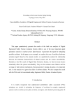
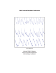
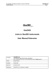
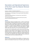
Seismic Monitoring System
for Nuclear Power Plants
CONTENT
Overview ...................................................................................................................................................... 03
System Centre.............................................................................................................................................. 04
Recorders ..................................................................................................................................................... 13
Sensors ........................................................................................................................................................ 18
Example System .......................................................................................................................................... 27
Reference List .............................................................................................................................................. 29
Company Presentation ................................................................................................................................. 32
INTRODUCTION
According to regional, national and international regulations, Nuclear Power Plants (NPP) need to be able to
mitigate potential effects of an earthquake.
Such mitigation can be achieved by utilising specific instrumentation for monitoring the earthquake ground
motions and the response of the plant features to these motions.
This type of instrumentation is called Seismic Monitoring System (SMS).
Main functions of the SMS are:
• Detection of any (significant) earthquake at plant location
• Provide data records of acceleration at defined locations
• Perform OBE/SSE exceedance evaluation
• Provide a report to the plant operator after an event
• Periodical self test execution
GeoSIG delivers complete SMSs for the NPP applications. These systems;
• Comply fully or exceed regional, national and international nuclear regulatory requirements
• Come with comprehensive certification and documentation, which can as well be supplied from
scratch for any particular requirement.
• Include powerful industrial computer for complex data processing based on different algorithms
including response spectra analysis
• Perform automatic analysis and evaluation of the earthquake impact on monitored structures
• Provide comprehensive and fast notification and reporting features
• Warrant the robustness, reliability and functionality to serve it main purpose
• Include self diagnostic and testing features to assure continuous system readiness to act once in a
life
• Present simplicity of operation, maintenance and upgrade
This document provides an overview of the SMS supplied by GeoSIG.
Upon request several more detailed documents are available, such as:
Sample Operator Report
Sample Design Report
Qualifications and Certificates
Regulatory Compliance
Reference Letters
Detailed Technical Notes on Example Systems
Terms and Conditions
OVERVIEW
The core of the GeoSIG Seismic Monitoring System (SMS; or SAS for Alarm System) is a Central
Processing Unit (CPU) rack mounted in a seismically and EMC safe cabinet together with an industrial PC
and relevant peripherals.
Detection / Recording Units (DRU's) consisting of accelerometers, seismometers or complete seismic station
packages are placed at remote locations that are connected to the CPU through shielded copper or fibre
optic cables.
The system has been designed in a way that it is not bound to a single topology. There could be only the
sensors or both sensors and data acquisition out in the field.
GeoSIG, unlike any other supplier, can offer three different and versatile solutions for the seismic
instrumentation of Nuclear Power Plants.
One is the Decentralised System, where
each measuring point has a seismic sensor
together with a dedicated recorder and there
is a system central controlling the overall
operation and providing system intervention
and maintenance.
Second one is the Centralised System
where only the seismic sensors are located
at the measuring points and all other
functionality are provided by the system
central.
And finally the Cascaded System, which is a combination
of the decentralised and centralised systems to provide a
more flexible deployment.
The system provides high modularity and flexibility so that
an upgrade is simplified and that as much as possible
existing elements can be reused.
State of the art GeoDAS software is utilized in
the CPU. GeoDAS monitors all DRU's in
parallel, as a result of the dedicated serial
communication links that are provided by the
system hardware.
For each measuring channel the recording threshold
and the alarm limit values can be set individually.
Detailed response spectrum limits can be fully defined
along with other parameters as required by relevant
regulations or customized user requirements.
Continuously monitoring the DRU's, the CPU detects
seismic events, generates associated alarms and
automatically processes the recorded data. It performs
periodical tests on the system and monitors the
system-wide state of the health as well as analyses
the detailed cause of any malfunction. A fully
automated Detailed Operator Report is provided a
few minutes after the occurrence of an earthquake.
SYSTEM CENTRE
SMS, Seismic Monitoring / Alarm System
GeoDAS Software
GeoSIG Ltd
Wiesenstrasse 39
8952 Schlieren
Switzerland
Tel:
Fax:
E-mail:
Web:
+41 44 810 21 50
+41 44 810 23 50
[email protected]
www.geosig.com
SMS / SAS Seismic Monitoring / Alarm System
Features*
Recording, advanced analysis and
annunciation according to project specific or
international regulations
Automatic exceedance evaluation
Reporting and alerting via relays, visual and
audible tools as well as printed matter
Project specific Automatic Event Processing
(AEP), Nuclear (NPP) or other features
Upto 48 remote stations or sensors
20 to 24-bit event based and/or continuous
recording
Common timing and triggering within the
system
Completely over-voltage protected
Continuous system-wide SOH monitoring
Seismically and EMC proven design
Comprehensive configuration of the whole
system via the enhanced computer interface
*The information provided is a typical overview. For each project a specific description is provided outlining the relevant system.
Outline
The core of the SMS / SAS is a Central Processing Unit The CPU monitors all DRU's in parallel, as a result of the
(CPU) with a multi-channel digital recorder system rack dedicated communication links that are provided by the
mounted in an industrial cabinet together with an industrial system hardware.
computer and relevant peripherals.
By monitoring continuously the DRU's, the CPU detects
Accelerometers, seismometers, complete seismic stations seismic events, generates associated alarms and
or sensor packages, which are referred to as Detection / automatically processes the recorded data. Also it
Recording Units (DRU's) are placed at remote locations performs periodical tests on the system and monitors the
can be connected to the CPU.
system-wide state of the health as well as analyses the
detailed cause of any malfunction. The result of the data
The system has been designed in a way that it is not
processing is provided in a report a few minutes after the
bound to a single topology. There could be only the
occurrence of an event.
sensors or both sensors and data acquisition out in the
field. Advantages of these topologies are briefly explained State of the art GeoDAS software is utilized in the CPU.
in the specifications section.
For each measuring channel the recording threshold and
the alarm limit values can be set individually. Detailed
The system has a great modularity and flexibility so that
project limits can be fully defined along with other
an instrumentation upgrade is simplified and that as much
parameters as required by relevant regulations or
as possible existing elements can be reused.
customized user requirements.
Specifications SMS / SAS Seismic Monitoring / Alarm System
Centralized Recording
De-centralized Recording
Advantages:
Simple devices in controlled area (analog sensors).
Simplified diagnostics and maintenance.
Higher compatibility with existing systems for upgrade.
Advantages:
Independent recording units increase redundancy and reliability.
Link from remote to central can use Fiber Optics.
Digital transmission between remote and central locations.
Cascaded / Hybrid Recording
Combination of the decentralised and centralised systems to provide a more flexible deployment.
Typical System Specifications
The below specifications provide a typical overview. For each project a specific description is provided outlining the relevant system.
Sensor
SMS/SAS system offers the most flexible sensor connectivity
options to cater for the needs of any measuring requirement.
Any matching type of sensor can be connected to the system.
Digitiser
A/D Converter:
Dynamic Range:
Sampling rates:
Bandwidth:
20 to 24 bits
108 to 146 dB
100 to 500 SPS per channel
40% of sampling rate
Data Recording
Pre-event-Time:
Post-event-Time:
Adjustable *
Adjustable *
Triggering
Type
Filtering:
Data Storage
Type:
Level (threshold) or STA/LTA trigger,
project specific triggers also available
User configurable
2 -128 Gbyte per 3 channels
and/or HDD, SSD in the computer
Data Analysis
GeoDAS software provides various analysis functions like filtering,
FFT, response spectra, etc. Other commercially available
evaluation software packages may alternatively be used.
Timing
Standard clock accuracy: Free running, based on TCXO
External time interfaces: GPS System accuracy < 1 sec.
Indicators
LED, Push button and/or Flatscreen indicators, may vary with
each project, based on requirements
Self Test / State of Health
Permanently active, self monitoring and user selectable, periodical
system test including comprehensive sensor, memory, filter, real
time clock, battery level and hardware tests.
Seismic Switch / Warning / Alarm Options
The warning option provides independent warning / error outputs
(relay contacts) based on user selectable criteria.
As separate acquisition module in the CPU with its own power
supply, remote sensor and cable; or independent DRU’s with
integral relays and CPU connection.
Communication Channel Options
Ethernet TCP/IP, landline, GSM/ GPRS/UMTS/3G, Serial
Power Supply
AC/DC Power supply:
External battery option:
230 VAC / 50 Hz or 115 VAC / 60 Hz
Rechargeable, 12 VDC, 24 to 100 Ah
Housing
19’’ cabinet in different sizes, floor standing or wall mounted.
*: Any value is useable, as long as it does not lead to data loss because of incorrectly configured or conflicting parameters.
Specifications subject to change without notice
Copyright © GeoSIG Ltd, 03.03.2014/ GS_SMS-SAS_Leaflet_V07.doc
GeoSIG Ltd
Wiesenstrasse 39
8952 Schlieren
Switzerland
Tel:
Fax:
E-mail:
Web:
+41 44 810 21 50
+41 44 810 23 50
[email protected]
www.geosig.com
GeoDAS NPP Features
Introduction
This document summarizes the features and functionalities of the GeoDAS used in the NPP seismic
Instrumentation Projects.
This document is intended be studied together with other GeoSIG technical documents relating to
NPP instrumentation to grasp the full context and the concepts mentioned.
If supplied within the context of an NPP Seismic Monitoring System, a special version of GeoDAS software is
delivered to be used to perform data analysis of the recorded time history, perform alarm and announcing if
the analysis determines that the seismic event has exceeded software thresholds established by the
structural engineers and operators of an NPP.
Summary of Operation
Site-specific parameters are set into the recorders in order to prepare the DRUs to detect and record any
events. The event files are kept in the recorder memory, which is a flash memory card. As soon as new
event occurs the relevant recorder settings like time, date, serial number, type of sensor and trigger level are
attached to the data file are saved to the recorder’s memory. This event file will be automatically downloaded
to the CPU computer. Further the event files are processed and analysed for Seismic, OBE and SSE
checks. Further analysis is possible with the ODV feature under manual mode.
GeoDAS NPP Features
In normal operation mode of the system, the CPU downloads event files from each DRU automatically. At
any time, a user can download any event recording manually by means of the Event Manager.
The recorders operate according to the specified settings, even without being connected to the CPU
computer, since the data is saved in the recorders memory.
The system computer performs a Response Spectra Analysis (RSA) of the time domain record to determine
the acceleration at the various frequencies. The structural SSE and OBE levels for the location of the
accelerometer may be entered into the system and the RSA compared against the SSE and OBE levels
established for each site.
When the RSA analysis exceeded the SSE and OBE levels the computer will generate a software alarm to
the GNC, which will in turn activate the Alarms that a SSE and/or OBE level has been exceeded. The system
may also be set up to automatically print out the time history, RSA with OBE & SSE levels, Fast Fourier
Transform (FFT) and Cumulative Absolute Velocity (CAV) on the HP laser printer.
The OBE alarm (OBE exceedance) is a combination the calculated elements done by GeoDAS it can be one
of the following combination:
•
•
•
•
•
CAV Only: Cumulated Absolute Velocity
CAV and OBE PSA: Cumulated Absolute Velocity and Pseudo Spectral Acceleration
OBE PSA Only: Pseudo Spectral Acceleration
OBE PSA and OBE SV: Pseudo Spectral Acceleration and Spectral Velocity.
CAV and OBE PSA and OBE SV: Cumulated Absolute Velocity and Pseudo Spectral Acceleration and
Spectral Velocity
Once the event data has been recorded in the individual Recording module it remains in the non-volatile
flash memory until removed by an authorized operator. Once an event has occurred the event record will be
automatically downloaded to the central system computer located in the central control panel where the
GeoDAS software will automatically perform an analysis of the time history record. Within a few minutes the
computer will have performed the preliminary analysis of the seismic event and if structural levels have been
exceeded provide an appropriate alarm making the system fully compliant to the new NPP guideline and
requirements.
The alarm threshold levels may be individually set on each channel. The recording alarm threshold will
cause the time domain recording of all acceleration signals exceeding the alarm threshold.
Authorized structural engineers and managers have found it useful to access the computer via the LAN and
download a particular event record for further analysis on their a computer at their desk. GeoSIG provides a
site license for the use of the GeoDAS software package allowing the use of the analysis package on as
many computers as the customer requires. GeoDAS allows limited and controlled access at various levels to
maintain security and allow for the effective maintenance and operator control to the system.
GeoSIG recommends that the customer establishes internal operating procedures for system test and
maintenance including a procedure for copying and archiving event records. A Read/Write CD is provided for
that purpose. The system performance, hard drive disc file space, computer memory and recording module
non-volatile memory has been sized to satisfy the system requirements and provide reliable long-term
operation.
The software has two modes of operation:
•
•
Standard, where the software is in the so-called “autodownload-mode”, downloading and analysing
automatically any events
Extended, where the user can stop the autodownload-mode and login to the DRUs manually
Specifications subject to change without notice
Copyright © GeoSIG Ltd, 25.06.2014/ GS_GeoDAS_NPP_Features_V06.doc
GeoDAS NPP Features
Seismic Check
After an event is recorded the CPU computer will retrieve the recorded data from the DRUs for further
analysis. Any reserve units will not be used for seismic check. Automatic analysis after retrieval of data in the
computer will decide if the event is seismic or non-seismic. The decision whether an event is seismic or nonseismic is based on several tests listed below.
Number
1
2
3
Table 1. Seismic / non seismic event detection
Tests for ‘seismic event Non-seismic Event
Seismic Event
detection’
if…
if…
Number of DRU locations Only 1 recorder triggered
2 of 6 recorders triggered
with recordings
Duration
Duration is below 2 s
Duration is above 2 s
FFT
FFT shows frequency peak FFT shows frequency peak below
above 33 Hz
33 Hz
The operator can repeat any of the tests referred to in the above table in deciding whether the event is
classed as seismic or not. In case of several DRUs triggered, the exact trigger times are compared. If the
differences are below three seconds, the recordings are classified as one event. The limits for the seismic
check parameters are as follows:
Table 2. Seismic check parameter settings and ranges
Parameter
Minimum
Maximum
Number of DRU locations triggered
1
6
Duration [s]
1
10
FFT Peak [Hz]
5
50
Standard Setting
2
2
33
The event is declared seismic if all criteria are fulfilled; otherwise it is treated as non-seismic.
Non-Seismic Event
After a non-seismic event the operator presses first the “ACK” button on alarm-panel to acknowledge the
alarm and then presses the “RESET” button to clear the alarm so that:
Table 3. Non-seismic event actions
Alarm
Alarm-panel:
Alarm Relays:
Monitor:
Action
“EVENT” indicator lamp goes out
“EVENT” relay goes back to normal state
Displays the results of the performed seismic check
The parameters defining the criteria for qualifying the recorded event as “non-seismic” will need to be
reviewed after a training period to verify that the filtering applies is correct. RSA, RSV and CAV calculations
are performed, but no OBE/SSE exceedance result is shown and no alarm is generated.
Seismic Event
In case of the event is classified as seismic by the system, RSA, RSV and CAV calculations are performed
and the results are compared with allowed levels for the following criteria to establish its degree of severity
and activate further alarms / relays. Results of the tests are displayed on the CPU computer monitor and are
also printed.
Specifications subject to change without notice
Copyright © GeoSIG Ltd, 25.06.2014/ GS_GeoDAS_NPP_Features_V06.doc
GeoDAS NPP Features
OBE/SSE Check
The OBE and SSE alarms are generated solely by the CPU computer utilizing GeoDAS and the alarm-logic.
It simply converts the received string to the appropriate electrical signals to drive the relay and alarm lamps.
RS-232
COMPUTER
ALARM LOGIC
OBE Alarm
SSE Alarm
Figure 1. OBE/SSE Alarm topology
In case of the event is classified as seismic by the system, RSA, RSV and CAV calculations are performed f
and the result is compared with allowed levels for the following criteria:
T
OBE/SSE Calculation
RSA
RSV
CAV
Table 4 Exceedance of individual OBE criteria
Criteria exceeded if…
• At least one component site level is exceeded
• At least one component site level is exceeded
• At least one component greater than 0.16 g-s1
T
T.
For example, if Reference sensor is not available, although the event has been classified as seismic, the
printed report will show an error message and data has to be retrieved locally from the DRUs by means of
laptop in case the unavailability of reference sensor data is due to some communication problem.
The parameter setting for seismic and OBE/SSE can be entered through windows. The figure below shows
the layout of the OBE settings window. The SSE settings can be entered in a window with the same layout,
named “SSE Exceedance”.
Figure 2. Event check parameters window
If the event calculation shows exceedance of OBE or SSE site levels, the computer sets the OBE or SSE
alarm and the following alarm will occur. OBE or/and SSE alarm will be reset manually by the operator.
Alarm
Alarm-panel:
Alarm Relays:
Monitor:
Table 5. OBE, OBE max. acceleration, CAV event actions
Action
• “OBE” or/and “SSE” indicator lamp flashes
• “EVENT”, “OBE” or/and “SSE” relay active
• Displays the results of the performed OBE/SSE check
TP1PT The unit [g-s] is used in the NRC Regulatory Guide 1.166 and refers to integrated acceleration in [g] over time in [s]. Within the
Seismic Instrumentation project all CAV values are treated in [mm/s]. 0.16 g-s corresponds to 1’570 mm/s.
Specifications subject to change without notice
Copyright © GeoSIG Ltd, 25.06.2014/ GS_GeoDAS_NPP_Features_V06.doc
GeoDAS NPP Features
Display of Processing Results
For each event recording, results of seismic, as well as OBE/SSE checks are displayed in a table. The below
figure shows an example of the “event check results” window.
T
Figure 3 . Event check results window
T
T
For each event, a context menu can be accessed (right-click) with the following functions:
•
•
The printing of any report can be repeated or forced manually at any time after an event.
Each event can be manually re-checked for Seismic, OBE or SSE.
After each event recording retrieved from the system that is classified as 'seismic', a report will be printed
automatically by the system, giving a summary of the check results (first page) and detailed waveforms for
each DRU (one page per unit).
An example report is illustrated in a separate document.
The software can be programmed such that the report will be printed also if an event is not classified as
‘seismic’. The waveforms included in the detailed waveform plots are:
1.
2.
3.
4.
Time-history (3 components)
RSA plot showing limits (3 components)
RSV plot showing limits (3 components)
CAV plot showing limits (3 components)
A report can be regenerated and reprinted at any time manually again. The connected printer is always
switched on. Further more, the printing of a report for a specific event can be repeated or forced manually by
the user. There will be a provision for the user to enter event-specific comment, such as earthquake
magnitude.
Specifications subject to change without notice
Copyright © GeoSIG Ltd, 25.06.2014/ GS_GeoDAS_NPP_Features_V06.doc
GeoDAS NPP Features
Processing Time Estimation
The timeline of system triggering / analysis is indicating in the next table. It is based on typical record length
of some 50 seconds (30 seconds shake + 10 seconds pre-event and 10 seconds post-events) acquired at
100 sps. The recorded file has a size of 45 kByte and has a download time of 12 seconds at 38400 bps.
U
Pos
Activity
Table 6. Step by step estimated elapsed time
Duration
Start
End
0
00:00:00
00:00:00
1
Earthquake waves hit the plant
2
From the continuous measurement stream, the trigger
system, after applying band-pass filtering detects an
acceleration exceedance.
Few ms
00:00:00
00:00:00
3
Seismic recorders report trigger to alarm module. Alarm
module applies Boolean logic to define if recording must
occur or not.
Few ms
00:00:00
00:00:00
4
Alarm module applies Boolean logic to define if an alarm
has to be generated.
Few ms
00:00:00
00:00:00
5
Common alarm received in control room.
Few ms
00:00:00
00:00:00
6
The computer is continuously monitoring the recorders for
new recorded event.
50 seconds
00:00:00
00:00:50
7
The computer detects recorded events. An event
condition is declared and it will downloads files as soon
they are ready.
6 x 15 = 90
seconds
00:00:50
00:02:20
8
Analyse process start by verifying if event is seismic
(number of triggered stations, duration and main
frequency).
10 seconds
00:02:20
00:02:30
9
OBE and SSE exceedance is checked.
30 seconds
00:02:30
00:03:00
10
OBE / SSE exceedance alarm generated is event is of
seismic origin.
Few ms
00:03:00
00:03:00
11
The event report is printed.
30 seconds
00:03:00
00:03:30
The main control is alarmed that an event occurred immediately when the earthquake hit the plant [5].
OBE/SSE alarm is (in case of exceedance) generated after about 3 minutes [10].
The event report is typically available after 3.5 minutes [11].
Logging
Within the CPU computer the events and results listed below will be logged. This allows the user to have
complete information about the alarms and the time they were performed.
Table 7. Logged information
Type
Logged information
System trigger
Source, date and time
OBE, OBE max. acceleration, CAV Alarm
Source, date and time
Power Loss
Source, date and time
System Error
Source, date and time
Test Results
Values, date and time
U
U
Specifications subject to change without notice
Copyright © GeoSIG Ltd, 25.06.2014/ GS_GeoDAS_NPP_Features_V06.doc
RECORDERS
GMSplus, Independent Recorders
CR-6plus, Central Recording System
GeoSIG Ltd
Wiesenstrasse 39
8952 Schlieren
Switzerland
Tel:
Fax:
E-mail:
Web:
+41 44 810 21 50
+41 44 810 23 50
[email protected]
www.geosig.com
!
Second generation of NetQuakes Recorder
!
3 or 6 channels, up to 1000 sps sampling rate
!
!
!
Broadband Seismic, Earthquake and Structural
measuring and monitoring
Low noise individual 24-bit Δ−Σ ADC per channel
!
Real-time Seismology for Freefield and Urban Areas
Internal built-in and/or external sensors
!
High Density Earthquake Monitoring Networks
!
Wired Ethernet, Wi-Fi and Serial links
!
Shake / Hazard Mapping based on Instrumental Data
!
Smart NTP timing, GPS time base, or time
synchronisation via radio channel or cable
!
Earthquake Early Warning and Rapid Response
!
Enhanced connectivity via landline modems, 3G
cellular devices and satellite links
!
Damage Estimation, Disaster Management
!
Seismic Alarm and Safe Shutdown
Ambient Vibration Testing (optionally fully wireless)
!
Recording to SD or CF cards, up to 128 GByte
!
!
USB interface for external storage and communication
devices
!
Induced Vibration Monitoring and Notification
!
Building Code Compliant Instrumentation
!
Continuous data recording to ringbuffers
!
Flexible configuration of multiple triggers
!
Simultaneous data streaming to several clients
!
On board data processing and evaluation
!
Rugged aluminium housing with levelling base
plate for easy installation
!
Configuration and status monitoring via Web Interface
compatible with Smartphones
!
Simple and secure communication over Internet with
full remote management
!
Internal battery, low power consumption
!
Alarm output with up to 4 relays flexibly configurable
for different types of events
!
Easily configurable interconnected networks with
common timing and triggering
Set-up and Configuration
An intuitive web interface is available for easy configuration with any web
browser. Alternatively the configuration file in XML format can be edited on site
through the instrument console, exchanged by replacing the memory card,
remotely from a server or through SSH. Even if the configuration file can be
manually edited at any time, a tool is provided to edit it securely.
Data Analysis
The GeoDAS software provides basic data evaluation in the field meeting the
plus
requirements of most scientific and engineering applications. Optionally GMS
can perform certain analyses onboard.
Sensor
Various GeoSIG sensors as well as a number of other third party sensors can be
housed internally or connected externally to the unit. In case of internal sensor,
plus
the levelling is done on the base plate of the GMS
via its three levelling
screws. The base plate is mounted using a single bolt during installation.
Digitizer
Channels:
A/D conversion:
DSP:
Dynamic range:
Sampling rate:
Max. bandwidth:
Anti Aliasing Filter:
3 or 6
24 bit Δ−Σ converters individual for each channel
32 bit output word length
146 dB (per bin @ 1 Hz rel. full scale rms)
137 dB @ 50 sps
1000, 500, 250, 200, 100, 50 sps per channel
DC to 250 Hz
Analog and digital FIR (finite impulse response)
CPU
Processor:
RAM:
Operating System:
ARM 400 MHz
64 MByte
GNU/Linux
Triggering
Several Trigger Sets can be defined in the instrument. Each set can be flexibly
configured regarding the source of trigger, main and advanced trigger
parameters, trigger processing and selected channels for storage. A voting logic
based on the monitored channels can be defined.
Time Base
Internal:
External:
Standard TCXO accuracy:
Accuracy after learn:
Accuracy with NTP:
Power Supply
Input voltage:
Type:
Internal battery:
Power consumption:
Autonomy:
Battery charger:
Indicators
" Green:
" Green:
" Yellow:
" Blue:
" Red:
Communication
Configuration, Data Retrieval:
Network requirements:
Trigger Filter
Fully independent high-, low- or bandpass trigger filters can be configured.*
Security:
Level Triggering
User adjustable threshold.*
Serial ports:
Baud rates:
STA/LTA Triggering
User adjustable STA / LTA values and STA/LTA trigger and detrigger ratio.
Event Recording
Pre-event memory:
Post-event duration:
1 to 720 seconds, typical
1 to 7200 seconds, typical
Event Summary and Parameters
Content:
PGA, PGV, PGD, SA (at 0.3, 1, 3 Hz)
Transmission delay:
User defined from trigger time
Ring Buffer
Usage:
Method:
Data Stream
Protocol/Compatibility:
Storage Memory
Size and Type:
Management:
Recording format:
Estimated Capacity:
User can request an event from any period of the
ring buffer by specifying the start time/date and the
duration from the console or remotely from a
server.
Ringbuffer files with configurable duration which
can be uploaded automatically to data server.
GSBU, SeedLink (Earthworm compatible)
8 GByte Removable SD Card,
Optionally Compact Flash Card
higher capacity up to 128 GByte on request
FAT32 or EXT4 formatted
Intelligent management of memory card capacity
using policies as per file type and ring buffer
capacity specification.
miniSEED with extended information encapsulated
into blockette 2000
Sampling rate [sps] x 0.4 [MB / day / 3 channel]
(example: 40 MByte / day / 3 channel @ 100 sps)
typical, since the data is compressed, capacity
depends on the context of the data.
Self Test
- Permanent self monitoring of hardware and software components without
affecting their normal operation.
- User-configurable periodical state of health (SOH) report based on
comprehensive test of instrument, which can be requested at any time.
- User-configurable periodical sensor test.
GMS
plus
Intelligent Adaptive Real Time Clock (IARTC)
NTP, optionally GPS, Wired or Wireless
Interconnection
±0.5 ppm (15 s/year) @ +25 °C
±2.5 ppm (75 s/year) @ -10 to +50 °C
Optionally higher accuracy TXCO’s available.
< ±0.5 ppm (15 s/year or 2 ms/h)
< ±4 ms typical, assuming reasonable access to
NTP servers
90 – 260 VAC / 50 – 60 Hz
Switched external UL approved power supply
screw mountable on any surface (e.g. wall)
12 VDC, 7.2 Ah, Rechargeable Lead-Acid
130 mA @ 12 VDC for 3 channels
200 mA @ 12 VDC for 6 channels
> 1 day, higher autonomy is optionally available
with external batteries.
Temperature compensated with optional battery
fault detection.
Active Charge LED
Run/Stop LED
Event/Memory LED
Network link/Traffic LED
Warning/Error LED
Via Ethernet, Wi-Fi, Serial line, Console,
or directly via removable memory card.
Fixed or Dynamic IP on Ethernet LAN and/or
Internet connection with Ethernet interface.
Wi-Fi (b/g/n) network with WEP, WPA, WPA2
security and Enterprise Mode
GeoDAS proprietary protocol over SSL
Checksum and software handshaking
2 ports standard, + 3 ports optional
Console: 115200 baud
Serial Stream: 38400, 57600, 115200 baud
Alarm / Seismic Switch / Warning / Notification Option
Alarms:
3 independent or 4 common relay contacts
for trigger alarm and/or error
SMS notification is optionally available
Alarm levels:
Configurable based on event triggers
(NO or NC selectable during order)
Relay Hold-On:
1 to 60 seconds
(User programmable)
Capacity:
The contacts are suitable for a low voltage
control. In case large load must be switched
then external relays should be implemented.
Max voltage:
125 V / 250 mA
Interconnected Network Option
Wired (Common Time and Trigger) or Wireless (Common Time) Interconnection
providing synchronisation among several units is optionally available. Common
Time and Trigger alternatively can be performed over the Wired/Wi-Fi network.
Modem Option
Internal or external modems of different types, including cellular 3G modems, are
available optionally.
Environment
Operational temperature:
Storage temperature:
Humidity:
Housing
Type:
Size:
Size with base plate:
Weight:
Protection:
Mounting:
Easy Transport:
-20 to +70 °C
-40 to +85 °C
0 to 100 % RH (non condensing)
Cast aluminium housing
296 x 175 x 140 mm (W x D x H)
296 x 225 x 156 mm (W x D x H)
4.7 kg (optional < 4 kg) excl. sensor, battery,
etc
0.3 kg internal sensor, 2.6 kg battery,
1.3 kg base plate, ask for other options
IP65 (NEMA 12), optionally IP67
Base plate with single bolt, surface mount.
plus
When base plate levelled and fixed, GMS
can be replaced without re-levelling.
Optional portability accessories are available
to facilitate short term measurements.
can be customised to suit particular or national regulations on request. Due to such customisation, not all of the functionality mentioned in this datasheet may be available.
Preliminary Specifications subject to change without notice
Copyright © GeoSIG Ltd, 20.08.2014/ GS_GMSplus_Leaflet_V14.doc
GeoSIG Ltd
Wiesenstrasse 39
8952 Schlieren
Switzerland
Tel:
Fax:
E-mail:
Web:
+41 44 810 21 50
+41 44 810 23 50
[email protected]
www.geosig.com
Unlimited number of channels by combining
modular (12 x 3) 36 channel modules
Structural Health and Response Monitoring
137 dB dynamic range
Ambient Vibration Testing
Individual 24-bit
Induced Vibration Monitoring and Notification
ADC per channel
Earthquake and Seismic Monitoring
Up to 500 sps adjustable sampling rate
Building Code Compliant Instrumentation
Recording on microSD cards
Seismic Alarm and Safe Shutdown
USB interface for external storage and
communication devices
Continuous and trigger based recording
Simultaneous data streaming to several clients
Wired Ethernet, optional enhanced connectivity
via external landline modems, 3G cellular
devices, satellite links and serial links
TCXO time base with GPS or NTP
synchronisation
Front View
Configuration and status monitoring via Web
Interface compatible with Smartphones/Tablets
Simple and secure communication over internet
or intranet with full remote management
Optionally available as drop-in replacement for
CR-4 Digitiser
Connection of sensor cables on terminals
Rear View
Optional alarm output with up to 4 independent
relays flexibly configurable for different types of
events
Extremely compact and modular
CR-6plus is a modern multichannel central monitoring and
recording system including a high performance data
handling module, providing an extremely flexible 24 Bit
multichannel recorder.
The CR-6plus continuously monitors the real-time data,
which can be recorded based on event detection and
continuously. The continuous ring buffer size, the preevent and post-event time, trigger thresholds and many
other parameters are fully user configurable.
Its design is based on years of experience in creating
solutions for earthquake, seismic, structural, dynamic and In addition to the real-time display of the measured data
static monitoring.
from each channel the system can provide statistical data
such as mean, max, min, and peak values.
Its modular architecture and industry standard interfaces
offer high versatility, easy expansion, upgradeability, and CR-6plus can optionally compare the monitored data to
long term availability of spare parts.
four fully independent alarm trigger criteria and provide
relay outputs.
Connection of the sensor cables is extremely easy and
fast with the versatile cable screw terminal design. All GeoDAS, a proven data acquisition and evaluation
inputs and outputs of the CR-6plus are protected with a package developed by GeoSIG, complements CR-6plus
field proven over voltage protection (OVP) system.
providing a highly flexible user-friendly capabilities, and
graphical, analytical and reporting tools with automation.
Data from acceleration, velocity, displacement, strain,
meteorological or any other type of sensors can be
monitored and recorded with superior data quality.
Overview
CR-6plus is a 19’’ rack module consisting of Slot-in Modules (SiMs)
inserted into vertical slots.
Each CR-6plus rack is expandable up to 36 channels and by
combining several CR-6plus systems, hundreds of channels can be
monitored.
System parameters of the CR-6plus are stored in the non-volatile
system memory to allow automatic recovery.
Power
DC Power:
AC Power:
Sensors
The CR-6plus offers the most flexible sensor connectivity options to
cater for the needs of any measuring requirement. Any type of
sensor complying with the CR-6plus signal input specifications can
be connected on the conveniently available screw terminals.
Solar Panels:
External battery:
CR-6plus Rack
Configuration:
Self-Test
User-configurable periodical sensor test and periodical state of health
(SOH) report based on comprehensive test of instrument, which can
be requested at any time.
Channels:
Digitiser SiM
Configuration:
Channels:
A/D Converter:
Dynamic range:
Base SiM modules:
- CR-6-SBC data handling SiM
ARM Cortex A8, 800 MHz
128 MB Flash, 128 MB RAM
- CR-6-OVPB over voltage protection SiM
- CR-6-WDB system watchdog SiM
Channel SiM modules:
- CR-6-DS digitiser SiM
- CR-6-OVPS sensor interface SiM
up to 36 channels
CR-6-DS
Mounted at the front of the CR-6plus Rack
up to 12 SiMs per one Rack
3 channels per SiM
24 Bit
per channel
with analog and digital FIR anti-aliasing
filters
146 dB (per bin @ 1 Hz rel. full scale rms)
137 dB @ 50 sps
Up to 500 SPS
40% of Sampling Rate
Sampling Rate:
Bandwidth:
Sensor Interface SiM
Configuration:
CR-6-OVPS
Mounted at the back of the CR-6plus Rack
up to 12 SiMs per one Rack
Channels:
3 channels per SiM
Input Signal:
10 VDC differential
2.5 VDC ± 2.5 VDC single ended
0 - 20 mA current loop
Sensor Power:
12, ±12 or 24 VDC
Data Recording
Type:
Triggering
Type
Pre-event-Time:
Post-event-Time:
Trigger filtering:
Data Stream
Protocol:
Storage Memory
Size and Type:
Management:
Recording format:
Continuous and/or event based
Level or STA/LTA trigger
1 to 720 seconds, typical
1 to 7200 seconds, typical
User configurable lowpass, highpass or
bandpass
GSBU, SeedLink
(Earthworm compatible)
8 GByte removable microSD Card,
Higher capacity available on request
Large USB storage available on request
FAT32 or EXT4 formatted
Intelligent management of memory card
capacity using policies as per file type and
ring buffer capacity specification.
miniSEED, optionally with extended
information encapsulated into blockette
2000.
Consumption:
Time Base
Internal:
External:
Std. TCXO accuracy:
Accuracy after learn:
Accuracy with NTP:
12 VDC
Available on request, AC/DC adaptor
with 230 VAC / 50 Hz or 115 VAC / 60
Hz.
typically 15 W with 36 channels
excluding the consumption of the
connected sensors
Available on request.
Available on request, 24 to 100 Ah with
battery protection in case of low battery
condition with automatic restart after
power is restored.
Intelligent Adaptive Real Time Clock
(IARTC)
NTP or GPS
±0.5 ppm (15 s/year) @ +25 °C
±2.5 ppm (75 s/year) @ -10 to +50 °C
Higher accuracy available on request
< ± 0.5 ppm (15 s/year or 2 ms/h)
< ± 4 ms typical, assuming reasonable
access to NTP servers
Communication Channel
Standard:
Ethernet TCP/IP
Optional:
Internal landline modem
External GSM modem
External Satellite modem
External GPRS modem
External UMTS/3G modem
User Interface
An intuitive web interface is available for easy configuration with any
web browser. Alternatively the configuration file in XML format can be
edited on site through the instrument console, exchanged by
replacing the memory card, remotely from a server or through SSH.
Even if the configuration file can be manually edited at any time, a
tool is provided to edit it securely.
Network based link allows the user optionally to interact with the unit
over the Internet, from anywhere around the world.
Alarm (Optional SiM)
Alarms:
Relay Hold-On:
Contacts:
Max voltage:
Environment / Housing
Operational temperature:
Storage temperature:
Humidity:
Rack Dimensions:
Housing:
Protection:
4 independent relay contacts for trigger
alarm and/or error (NO and NC contacts
available)
1 to 60 seconds (User programmable)
Suitable for a low voltage control. In case
large loads must be switched then
external relays should be implemented.
125 V / 250 mA
-20 °C to +70 °C
-40 °C to +85 °C
0 % to 100 % (non condensing)
19’’ rack, 3 HU, 350 mm depth
Various fixed or portable housings
available on request
Housings
with variable protection
available on request
Preliminary Specifications subject to change without notice
Copyright © GeoSIG Ltd, 05.01.2015/ GS_CR-6plus_Leaflet_V09.doc
SENSORS
AC-23 Servo-Accelerometer
AC-73 Force Balance Accelerometer
GeoSIG Ltd
Wiesenstrasse 39
8952 Schlieren
Switzerland
Tel:
Fax:
E-mail:
Web:
+41 44 810 21 50
+41 44 810 23 50
[email protected]
www.geosig.com
AC-23 / AC-22 / AC-21 Accelerometer
Features
!
Full Scale ± 0.1, 0.2, 0.5, 1, 2 and 4g
jumper selectable
!
Bandwidth 0.1 Hz to 100 Hz
(optional 200 Hz)
!
Dynamic range > 125 dB
!
Excellent temperature stability
!
Strong-Motion, Free field and Industrial
applications
!
Downhole version (AC-23-DH) is also
available
!
Different housing and mounting options
are available
!
Single Bolt Mounted Enclosure provides
up to ± 10° of Levelling Adjustment
Outline
The AC-23 package is a triaxial accelerometer The AC-2x is housed in a sealed cast aluminium
sensor designed for Strong Motion and industrial housing with the dimensions of 195 x 112 x 96
applications where a high sensitivity is required. mm. The housing also offers a single bolt
The AC-2x series are state-of-the-art servo- mounting system with three levelling screws.
accelerometers based on standard exploration Stainless steel housings as well as internal
geophone mass-spring system with electronic mounting inside GSR-xxAH housing options are
feedback. Having remarkable temperature and available.
aging stability because of the very simple With the help of the TEST LINE the sensor can
principle,
the
AC-2x
rarely
requires be easily and completely tested. Full scale is
maintenance.
user selectable on site by setting the internal
The outstanding dynamic range performance jumpers.
and linearity of the AC-2x which is more than The AC-2x accelerometer is directly compatible
125 dB at ± 2 g full scale within the 0.1 to 50 Hz with the GeoSIG recorders.
range, makes this accelerometer a perfect
sensor for many applications.
Triaxial, biaxial and uniaxial configurations are
all available in surface and downhole models,
complementing the versatile useability of the
AC-2x.
Specifications AC-23 / AC-22 / AC-21 Accelerometer
Alignment**
H–H–V
■
X–Y
H–H
■
X (or Y) – Z
H–V
■
X (or Y)
H
■
Z
V
■
* i : Internal sensor ** H: Horizontal, V: Vertical
Full Scale Range:
Jumper selected in range
± 0.1, ± 0.2, ± 0.5, ± 1, ± 2 and 4g
for ± 10 V diff at output
AC-23 NPP: ± 0.5, ± 1 and ± 2g
Connector Pin Configuration
Pin 1-2, 3-4, 5-6
Signal output for axis X, Y, Z
Pin 7-8
Test input, Digital test-pulse (0 – 12 V)
Pin 9-10
+12 VDC Power Supply
Pin 11-12
Auxiliary input
Case
Shielded Ground
Environment/Housing
Housing Type:
Cast aluminium
Sealed access cover
195 x 112 x 96 mm
2.5 kg
IP 65
optional IP 68
- 20 to 70 °C (operating)
- 40 to 90 °C (non-operating)
0 to 100 % (non-condensing)
Floor or wall mounting (to be specified in
order)
Single bolt, surface mount, adjustable
within ± 10°
Housing Size:
Weight:
Index of Protection:
Temperature Range:
*
165.0
.5
R1
+2.0
23.0
-2.0
.0
24
23.0
4.0
Damping:
Offset Drift:
Span drift:
Full Scale output:
Mounting:
68.0
Dynamic Range:
Linearity:
Accuracy:
Cross Axis Sensitivity:
Bandwidth:
Humidity:
Orientation:
28.0
Servo-accelerometer based on
geophones with feedback
>125 dB effective at ± 2 g full scale
0.1 %
± 0.4 dB max over the bandwidth
1%
0.1 Hz (1 pole) to 100 Hz (1 pole)
optional 200 Hz
0.7 critical
0
< 1 mV/ C
0
< 200 ppm/ C
0 ± 10 V differential (20 Vpp)
optional
2.5 ± 2.5 V single-ended (5 Vpp)
0 to 20 mA current loop
14.0
Sensor Element
Type:
181.5
15.0
6.5
6.0
3
]
16.0
80.0
96.0
112.0
10
2
6.0
R
R
3.0
3.0
1.5
10
165.0
1
Standard AC-23
10
-1
-3
10
2
Options
Cable & connector:
10
-2
-4
10
10
10
-3
-5
10
1
10
-4
-6
10
10 -1
10
-5
-7
10
Housing:
10 -2
10
-6
-8
10
10 -3
10
-7
-9
10
Mounting:
Floor mounted, Full scale ± 2 g,
2 m cable with cable inlet and recorder
mating connector, concrete anchor bolt
and user manual on CD
Cable connector
Metallic, Shielded, IP67, 12 pins, male
optional MIL, Bendix PT07A 14-19P
Cable with shielded twisted pairs for any
length (including mating sensor
connector) with open end
Cables for connection to GeoSIG
recorder
Connector on user specification mounted
at cable end
Watertight IP 68 housing
Downhole housing (AC-2x-DH)
Stainless steel protective housing
As internal sensor
Wall mounted
10 -4
10
-8
0
-1
10
10
-5
Ordering Information
Specify:
Type of AC-2x, full scale range, and
other applicable options
3
10
10
2
10
1
10 -1
10 -2
10
-9
1
-1
10
10 -6
10 -3
Velocity [mm/s]
Sensor with Cable Inlet: 200 mm from sensor housin
R
-2
10
10
10
m
en
t[
D
is
]
[g
-1
4
3
Space Allowance for the Connector and Cable:
* Minimum
Sensor with Connector: 300 mm from sensor housing
pl
a
n
5
10
15.0
3 x M6
ø9
VE-1x
VE-2x
VE-3x
VE-5x
VE-5x-BB
VE-5x-DIN
AC-2x
AC-4x
AC-6x
AC-7x
10
10
76.0
ø 15
ce
m
tio
ra
1
10
m
le
ce
Ac
6
41.0
7
10
10
152.0
See Plot
56.0
10
15.0
R
Measuring Range:
41.0
195.0
99.0
AC-23 or AC-23i*:
AC-22-H or AC-22-Hi*:
AC-22-V or AC-22-Vi*:
AC-21-H or AC-21-Hi*:
AC-21-V or AC-21-Vi*:
Axes
X–Y–Z
12 VDC regulated (10 to 15 V)
40 mA @ 12 V
Binder / Coninvers type RC
All pins are protected
12.0
Triaxia
l
Biaxial
Uniaxi
al
Configurations:
Power
Supply Voltage:
Consumption:
Mating:
Overvoltage Protection:
10.0
General Characteristics
Application:
Strong Motion earthquake survey
Industrial applications requiring high
sensitivity
Frequency [Hz]
Specifications subject to change without notice
Copyright © GeoSIG Ltd, 03.09.2014/ GS_AC-23_Leaflet_V12.doc
GeoSIG Ltd
Wiesenstrasse 39
8952 Schlieren
Switzerland
Tel:
Fax:
E-mail:
Web:
+41 44 810 21 50
+41 44 810 23 50
[email protected]
www.geosig.com
AC-23 / AC-22 / AC-21-DH Downhole Accelerometer
Features
! Full Scale ± 0.1, 0.2, 0.5, 1, 2 and 4g
jumper selectable
! Bandwidth 0.1 Hz to 100 Hz
(optional 200 Hz)
! Dynamic range > 125 dB
! Excellent temperature stability
! Strong-Motion, Free field and Industrial
applications
! No field adjustment required
! Strong mechanical design
! Fits in 3 inch casing
Outline
The AC-23-DH sensor package is a triaxial
accelerometer designed for borehole applications
regarding Strong Motion earthquake survey and
monitoring.
The AC-2x-DH sensors are servo-accelerometers
based on a standard exploration geophone massspring system with electronic feedback. This type of
sensor gives a very good stability versus temperature
or aging because of the very simple principle.
The sensor does not require maintenance and has
very low aging drift. With the help of the TEST LINE
the sensor can be easily, completely tested.
The family of AC-2x-DH accelerometer is directly
compatible with the GeoSIG recorders.
The downhole casing contains the entire sensor
system. The sensor is connected through Overvoltage
Protection stage to the recorder at the surface with a
cable.
Using inclinometer tubes and the provided guiding
wheels, the sensor can be oriented before insertion in
the tube.
Typical 100 mm casing or hole diameter
Surface
Borehole with or
without casing
Soft
material
Sand
Sand
CABLE
Inclinometer
tube
SENSOR
Hard
rock
Concrete
Concrete
Sand
GUIDE
Sand
Specifications AC-23 / AC-22 / AC-21-DH Downhole Accelerometer
Triaxial
Configurations:
Strong Motion earthquake survey,
Industrial applications requiring high
sensitivity.
AC-23:
AC-22-H:
AC-22-V:
AC-21-H:
AC-21-V:
Biaxial
Uniaxia
l
General Characteristics
Application:
■
■
■
Axes
Alignment**
X–Y–Z
H–H–V
X–Y
H–H
X (or Y) – Z
H–V
■
X (or Y)
H
■
Z
V
** H: Horizontal, V: Vertical
Full Scale Range:
Factory configurable to:
± 0.1, ± 0.2, ± 0.5, ± 1, ± 2 and ± 4g
for ± 10 V diff at output
AC-23 NPP: ± 0.5, ± 1 and ± 2g
Sensor Element
Type:
Servo-accelerometer based on
geophones with feedback
>125 dB effective at ±2 g full scale
0.1 %
± 0.4 dB max over the bandwidth
1%
0.1 Hz (1 pole) to 100 Hz (1 pole)
optional 200 Hz
0.7 critical
0
< 1 mV/ C
0
< 200 ppm/ C
0 ± 10 V differential (20 Vpp)
See Plot
Dynamic Range:
Linearity:
Accuracy:
Cross Axis Sensitivity:
Bandwidth:
Damping:
Offset Drift:
Span drift:
Full Scale output:
Measuring Range:
7
10
6
10
5
10
4
10
3
10
2
3
10
Mating:
Overvoltage Protection:
Environment/Housing
Housing Type:
Housing Size:
Weight:
Aluminium cylinder, fully sealed
Diameter 54 mm, length 420 mm
3.5 kg
∅ 54 mm
420 mm
Index of Protection:
Temperature Range:
Humidity:
Orientation:
IP 68, up to 10 bars water pressure
- 20 to 70 °C (operating)
- 40 to 90 °C (non-operating)
0 to 100 %
Using 3” inclinometer casing (Figure 1)
with included guidewheels (Figure 2).
10
2
D
is
]
[g
pl
a
n
1
Standard AC-23-DH
-2
10
Optional Accessories
DH-TUBE
1
-1
10
VE-1x
VE-2x
VE-3x
VE-5x
VE-5x-BB
VE-5x-DIN
AC-2x
AC-4x
AC-6x
AC-7x
10
Installation kit:
10
-1
-3
10
DH-BALL
10
-2
-4
10
10
10
-3
-5
10
Ordering Information
Specify:
1
Full scale ± 2 g, recorder mating
connector and user manual on CD.
Borehole cable length to be defined.
3” inclinometer casing as in figure 1 in
sections of 3 meters with coupling
elements.
All required tools and fixation
consumables for up to 100 meters of
casing.
Glass Balls for settlement of downhole
sensor (25 kg bag)
10
-4
-6
10
Type of AC-2x-DH, acceleration full
scale, depth of borehole and total cable
length.
10 -1
10
-5
-7
10
10 -2
10
-6
-8
10
10 -3
10
-7
-9
10
10 -4
10
-8
0
-1
10
10 -5
3
10
10 2
10
1
10 -1
10
10 -2
10
-9
1
-1
10
10 -6
-3
Velocity [mm/s]
12 VDC regulated (10 to 15 V)
40 mA @ 12 V
Metallic, Shielded, IP67, 12 pins, male
mounted at end of cable.
Other connectors on request.
Binder / Coninvers type RC
All pins are protected
Connector Pin Configuration
Pin 1-2, 3-4, 5-6
Signal output for axis X, Y, Z
Pin 7-8
Test input, Digital test-pulse (0 / 12 V)
Pin 9-10
+12 VDC Power Supply
Pin 11-12
Auxiliary input (unused)
Case
Shielded Ground
ce
m
tio
ra
en
t[
le
ce
Ac
m
m
]
10
10
Interface
Power supply voltage:
Consumption:
Connector:
Frequency [Hz]
Figure 1
Figure 2
Specifications subject to change without notice
Copyright © GeoSIG Ltd, 03.09.2014/ GS_AC-23-DH_Leaflet_V11.doc
GeoSIG Ltd
Wiesenstrasse 39
8952 Schlieren
Switzerland
Tel:
Fax:
E-mail:
Web:
+41 44 810 21 50
+41 44 810 23 50
[email protected]
www.geosig.com
AC-73 / AC-72 / AC-71 Force Balance Accelerometer
True Electro-mechanical
Force Balance Accelerometer
Broadband Seismic, Earthquake and
Structural measuring and monitoring
Dynamic Range 165 dB
User selectable Full Scale range
± 0.5, 1, 2, 3 or 4 g
Bandwidth from DC to 200 Hz
Exemplary Offset stability
Temperature and drift compensation
Robust suspension system
Single Bolt Mounted Enclosure with
up to ± 10° of Leveling Adjustment
Integrated Bubble Level
The AC-73 sensor package is a true electro-mechanical
triaxial downhole accelerometer designed for broadband
earthquake monitoring and applications requiring highly
sensitive and rugged sensors with minimum maintenance
and a simple method for periodic testing.
The DC response allows the sensor to be easily repaired,
tilt tested or recalibrated in the field. With the help of the
test line the AC-73 accelerometer can be completely
tested assuring proper operation and accurate
acceleration measurement. This test line is internally
connected to the external world only when a given
The rugged mass suspension moving coil system
command is sent to the sensor to avoid any noise pick-up
improves the signal to noise ratio. The magnetic system
through the test input.
and capacitive position sensors offer symmetrical controls
for the accurate electronic centring of the mass. At rest The AC-73 is equipped with electronic offset adjustment
the accelerometer mechanism is in balance and no features that make its installation very user friendly. This
electrical output is generated.
powerful feature allows the users to install the AC-73
without mechanical offset adjustment and fine levelling.
In case of a ground motion, AC-73 yields an electrical
output proportional to the current used to keep the mass The sensor can be powered from 9.5 to 18 VDC source
centred. This output signal is precisely calibrated to with the advantage that its power input is insulated from
provide a signal at the utmost accuracy and with a lowest the sensor’s electronic ground. This avoids ground loops
possible noise level. The symmetrical positioning system and reduces noise induced through the power supply.
incorporated with the force balance accelerometer
principle, the accelerometer faithfully keeps its scaling
and calibration even under extreme conditions.
AC-73 or AC-73i*:
AC-72-H or AC-72i-H*:
AC-72-V or AC-72i-V*:
AC-71-H or AC-71i-H*:
AC-71-V or AC-71i-V*:
Uniaxial
Triaxial
General Characteristics
Configurations:
Biaxial
Specifications AC-7x
Axes
X–Y–Z
Alignment**
H–H–V
X–Y
H–H
X–Z
H–V
X
H
Z
V
±2 std., ± 0.5, 1, 3 or 4 g
user selectable at field
Sensor Element
Type:
Environment/Housing
Housing Type:
True Electro-mechanical
Force Balance Accelerometer
165 dB (per bin rel. full range)
156 dB (per bin rel. full scale rms)
134 dB (0.02 – 50 Hz, integrated PSD)
< 0.1 %
< 0.5 %
DC to 200 Hz
0.7 ±0.1 critical
0.0005 g / °C
200 ppm / °C
0 ±10 V differential (20 Vpp)
< 0.001 % of full scale
2.5 to 20 V/g
100 ohms
Dynamic Range:
Nonlinearity:
Cross Axis Sensitivity:
Bandwidth:
Damping:
Offset Drift:
Span Drift:
Full Scale Output:
Hysteresis:
Sensitivity:
Output impedance:
9.5 to 18 VDC, single supply
55 mA @12 V
Metallic, Shielded, IP67, 12 pins, male
All pins are protected
Connector Pin Configuration
Pin 1-2, 3-4, 5-6
Signal output for axis X, Y, Z
Pin 7-8
Test input, Digital 0/12 V / GND
Pin 9-10
12 VDC insulated power supply input
Pin 11-12
Reserved
Case
Shield connection
* i : Internal sensor ** H: Horizontal, V: Vertical
Full Scale Range:
Power
Supply Voltage:
Consumption:
Connector:
Overvoltage Protection:
Cast aluminium
Sealed access cover
195 x 112 x 96 mm
3.0 kg
IP 65
optional IP 68
-20 to 70 °C (operating)
-40 to 75 °C (non-operating)
0 to 100 % (non-condensing)
Can be configured for mounting in any
position (please specify at order).
Single bolt, surface mount, adjustable
within ±10°
Housing Size:
Weight:
Index of Protection:
Temperature Range:
Humidity:
Orientation:
Mounting:
*
165.0
5
R 1.
+2 .0
23.0
-2.0
10.0
4.0
28.0
4
14.0
23.0
AC-73 Measuring Range
in com parison w ith
Average Size of Earthquake Signals
12.0
68.0
.0
24
10
181.5
41.0
195.0
15.0
4g
15.0
152.0
6.5
3
6.0
76.0
56.0
20
41.0
R
10
15.0
ø 15
2
Minimum Space Allowance for the Connector and Cable:
* Sensor
with Connector: 300 mm from sensor housing
3 x M6
99.0
16.0
Sensor with Cable Inlet: 200 mm from sensor housin
80.0
112.0
96.0
ø9
10
6.0
40
R
.
3.0
1.5
R
1
M 7.5max
R
3 .0
10
M 5.5
100
M 4.5
M 3.5
M 7.5
80
M 7.5
-1
10
M 2.5
100
-2
10
M 6.5
120
M 5.5
-3
10
165.0
.
60
dB rel. Full Scale
Amplitude [(cm/s^2)/sqrt(Hz)]
M 6.5
The text on this image is best readable on the digital document
Standard AC-7x
Options
Full Scale Output:
Cable & connector:
M 4.5
Local EQs upt o 10 km
-4
10
140
M 3.5
Magnit ude
AC-73
Floor mounted, Full scale ± 2 g,
2 m cable with cable inlet and GeoSIG
recorder mating connector, concrete anchor
and user manual on CD
-
Regional EQs upt o 100 km
160
M agnit ude
-
-5
10
0.001
0.01
0.1
1
10
Frequency [Hz]
100
1000
- A C-73 range based o n A NSS-Recommended Lo w-Gain A cceleromet er Noise A nalysis;
- Oct ave-wide freq uency-amp lit ude curves f or various magnitud e-distance bins based on
- Clint on, J.F., " M odern Digit al Seismo lo gy - Inst rument ation, A mplit ude St udies
- in t he Engineering Wo rld" , PhD Thesis, 2 004
Housing:
Mounting:
Ordering Information
Specify:
-
0 to 20 mA current loop
Frame connector (no cable inlet)
Mating connector (for frame connector)
Cable with shielded twisted pairs for any
length with open end
Connector on user specification
mounted at cable end
See separate cable & connector options
sheet
Watertight IP68 housing
Stainless steel protective housing
See separate sensor orientation options
sheet
Type of AC-7x, full scale range, and other
applicable options
Preliminary Specifications subject to change without notice
Copyright © GeoSIG Ltd, 06.11.2013/ GS_AC-73_Leaflet_V15.doc
GeoSIG Ltd
Wiesenstrasse 39
8952 Schlieren
Switzerland
Tel:
Fax:
E-mail:
Web:
+41 44 810 21 50
+41 44 810 23 50
[email protected]
www.geosig.com
AC-73-DH / AC-72-DH / AC-71-DH Force Balance Accelerometer
True Electro-mechanical
Force Balance Accelerometer
Broadband Seismic, Earthquake and
Structural measuring and monitoring
Extremely robust downhole housing
Suitable for borehole diameters
of 100 mm and larger
Dynamic Range 165 dB
Full Scale ± 0.5, 1, 2, 3 or 4 g
Bandwidth from DC to 200 Hz
Temperature and drift compensation
Robust suspension system
Proprietary iSensor™ interface
Built-in compass as well as
tilt, temperature and humidity sensors
The DC response allows the sensor to be easily repaired,
tilt tested or recalibrated in the field. With the help of the
test line the AC-73-DH accelerometer can be completely
tested assuring proper operation and accurate
acceleration measurement. This test line is internally
connected to the external world only when a given
command is sent to the sensor to avoid any noise pick-up
The rugged mass suspension moving coil system
through the test input.
improves the signal to noise ratio. The magnetic system
and capacitive position sensors offer symmetrical controls The AC-73-DH is equipped with electronic offset
for the accurate electronic centring of the mass. At rest adjustment features that make its installation very user
the accelerometer mechanism is in balance and no friendly. This powerful feature allows the users to install
the AC-73-DH without mechanical offset adjustment and
electrical output is generated.
fine levelling.
In case of a ground motion, AC-73-DH yields an electrical
output proportional to the current used to keep the mass The advanced iSensor™ interface allows easy
centred. This output signal is precisely calibrated to deployment using built-in hardware like compass as well
provide a signal at the utmost accuracy and with a lowest as tilt, temperature and humidity sensors.
possible noise level. The symmetrical positioning system
The sensor can be powered from 9.5 to 18 VDC source
incorporated with the force balance accelerometer
with the advantage that its power input is insulated from
principle, the accelerometer faithfully keeps its scaling
the sensor’s electronic ground. This avoids ground loops
and calibration even under extreme conditions.
and reduces noise induced through the power supply.
The AC-73-DH sensor package is a true electromechanical triaxial downhole accelerometer designed for
broadband earthquake monitoring and applications
requiring highly sensitive and rugged sensors with
minimum maintenance and a simple method for periodic
testing.
AC-73-DH:
AC-72-H-DH:
AC-72-V-DH:
AC-71-H-DH:
AC-71-V-DH:
Uniaxial
Triaxial
General Characteristics
Configurations:
Biaxial
Specifications AC 7x-DH
Axes
X–Y–Z
Alignment**
H–H–V
X–Y
H–H
X–Z
H–V
X
H
Z
V
** H: Horizontal, V: Vertical
Full Scale Range:
Power
Power input:
Supply Voltage:
Consumption:
Overvoltage Protection:
±2 std., ± 0.5, 1, 3 or 4 g
Sensor Element
Type:
True Electro-mechanical
Force Balance Accelerometer
165 dB (per bin rel. full range)
156 dB (per bin rel. full scale rms)
134 dB (0.02 – 50 Hz, integrated PSD)
< 0.1 %
< 0.5 %
DC to 200 Hz
0.7 ±0.1 critical
0.0005 g / °C
200 ppm / °C
0 ±10 V differential (20 Vpp)
< 0.001 % of full scale
2.5 to 20 V/g
100 ohms
Dynamic Range:
Nonlinearity:
Cross Axis Sensitivity:
Bandwidth:
Damping:
Offset Drift:
Span Drift:
Full Scale Output:
Hysteresis:
Sensitivity:
Output impedance:
iSensor™ interface
iSensor™ interface is a state of the art innovative and proprietary
hardware and software interface developed by GeoSIG, which allows
through its special computer software, the operation, control, logging and
data export for the built-in:
- compass
- tilt sensor
- temperature sensor
- humidity sensor
Insulated
9.5 to 18 VDC, single supply
80 mA @12 V, excl. options
All pins are protected with double stage
barrier.
Connector Pin Configuration
Pin 1-2, 3-4, 5-6
Signal output for axis X, Y, Z
Pin 7-8
Test input, Digital 0/12 V / GND
Pin 9-10
12 VDC insulated power supply input
Pin 11-12
iSensor™ interface (RS-485)
Case
Shield connection
Environment/Housing
Housing Type:
Housing Size:
Weight:
Index of Protection:
Temperature Range:
Aluminium
Optional Stainless Steel
89 mm x 502 mm
4.2 kg (typical configuration)
Watertight upto 10 bar (100 m)
-20 to 70 °C (operating)
-40 to 75 °C (non-operating)
AC-73 Measuring Range
in com parison w ith
Average Size of Earthquake Signals
89 mm
4
10
4g
3
10
502 mm
20
2
10
.
40
1
Standard AC-7x-DH
Amplitude [(cm/s^2)/sqrt(Hz)]
M 6.5
60
M 5.5
100
M 4.5
M 3.5
M 7.5
80
M 7.5
-1
10
M 2.5
100
-2
10
M 6.5
120
M 5.5
-3
10
dB rel. Full Scale
10
Full scale ± 2 g,
with cable inlet and user manual on CD
.
M 7.5max
Options
Cable & connector:
Ordering Information
Specify:
- See separate cable and connector
options sheet
- Connector on user specification can be
mounted at cable end
Type of AC-7x-DH, full scale range, depth of
deployment, cable length, and other
applicable options
M 4.5
Local EQs upt o 10 km
10
140
M 3.5
Magnit ude
-4
AC-73
Regional EQs upt o 100 km
160
M agnit ude
-5
10
0.001
0.01
0.1
1
10
Frequency [Hz]
100
1000
- A C-73 range based o n A NSS-Recommended Lo w-Gain A cceleromet er Noise A nalysis;
- Oct ave-wide freq uency-amp lit ude curves f or various magnitud e-distance bins based on
- Clint on, J.F., " M odern Digit al Seismo lo gy - Inst rument ation, A mplit ude St udies
- in t he Engineering Wo rld" , PhD Thesis, 2 004
Preliminary Specifications subject to change without notice
Copyright © GeoSIG Ltd, 05.02.2014/ GS_AC-73-DH_Leaflet_V06.doc
EXAMPLE SYSTEM
Beznau NPP in Switzerland
Beznau Nuclear Power Plant
Seismic Instrumentation Network
Switzerland
Project Overview
Axes
18
Sensors
6
Digitisers/
Recorders
6
System
Center
1 Data Center
Communication
Cable/modem
Duration
(weeks)
40
Beznau NPP
Unit 1
Unit 2
G2
G3
F1
N1
G1
F1:
F2:
N1:
G1:
G2:
G3:
F2
Freefield at surface
Freefield on bedrock
State of Emergency building, mat foundation
Security building, mat foundation
Security building, operation floor level 340
Security building, operation floor level 340
Scope:
Nuclear Power Plant (NPP) safety monitoring against seismic motions, and other ambient dynamic loads to:
(i) Evaluate and observe structural safety and integrity as well as safe operation,
(ii) Assess and compare the behaviour against the seismic design criteria,
(iii) Develop and improve emergency and safety measures as well as awareness,
(iv) Contribute to regional seismic database.
System:
AC-23 force balance accelerometers, GSR-18 digitiser/recorders and one Central Processing Unit (CPU).
All stations store the motion signals detected by the sensors in local recorders, for redundancy.
GeoDAS software is utilized to: i) monitor the stations, ii) download event recordings automatically, iii) check
system state of health, which can be used to analyze the detailed cause of any malfunction, iv) Analyze
downloaded data by means of seismic and OBE/SSE checks, v) issue alarms.
Recording threshold and the alarm limit values can be set individually for each measuring channel.
Alarm transmission and communication between stations and the CPU via fiber-optic cable.
Self-monitoring and testing facilities for periodic testing of the entire measurement chain.
Outputs:
Three alarm levels: trigger, calculated, system failure.
Laser printed seismic event records including 3 component time-history and RSA, RSV and CAV plots with limits.
Data is stored on event basis in case a dynamic event is detected.
Client:
Nordostschweizerische Kraftwerke (NOK)
GeoSIG Ltd
Wiesenstrasse 39, 8952 Schlieren Switzerland
Tel: +41 44 810 2150, Fax: +41 44 810 2350
Web: www.geosig.com, e-mail: [email protected]
Copyright © GeoSIG Ltd, 30 June 2014 / NPP_Example_Beznau._V01.doc
REFERENCE LIST
World Wide Nuclear Power Plants with GeoSIG
Instrumentation
GeoSIG Ltd
Wiesenstrasse 39
8952 Schlieren
Switzerland
Tel:
Fax:
E-mail:
Web:
+41 44 810 21 50
+41 44 810 23 50
[email protected]
www.geosig.com
Selected NPPs Instrumented with GeoSIG Instruments
In the past decades, GeoSIG Instruments have been delivered to more than 70 NPP's in more than 15
countries worldwide. Some of the NPP's around the world, which are instrumented with GeoSIG Instruments,
are listed below.
Country
Argentina
Armenia
Belgium
Belgium
Bulgaria
Canada
Canada
China
Czeck Republic
France
Germany
Hungary
Lithuania
Lithuania
Slovak Republic
Slovak Republic
South Korea
South Korea
South Korea
South Korea
South Korea
South Korea
South Korea
South Korea
South Korea
South Korea
South Korea
South Korea
Spain
Spain
Spain
Spain
Switzerland
Switzerland
Switzerland
Switzerland
Switzerland
Switzerland
Switzerland
Taiwan
USA
GS_NPP_Reference_List_V04.doc
Project
Embalse
Metsamor
Doel
Tihange
Kozloduy
Gentilly
Pickering
Tianwan
Temelín
T
Marcoule
KMK Mülheim-Kärliche
Paks
xt
Ignalina - Modernization
Ignalina
Bohunice
Mochovce
ASTS for 6 Reactors
Shin-Kori Unit 3 & 4 Extension
Shin-Wolsong Unit 3 & 4 Extension
ASTS for 20 Reactors
Shin-Kori Unit 3 & 4
Waste Storage Facility (LILW)
Shin-Wolsong
Shin-Kori Unit 1 & 2
Wolsong - Upgrade
Ulchin Unit 5 and 6
Kori
Wolsong Unit 1 & 2
José Cabrera (Zorita) - Upgrade
Trillo
Vandellos
José Cabrera (Zorita)
Mühleberg
Leibstadt Phase 2
Beznau Phase 2
Gösgen Phase 2
Gösgen Phase 1
Leibstadt Phase 1
Beznau Phase 1
Maanshan
Susquehanna - Upgrade
1
GeoSIG Ltd
Wiesenstrasse 39
8952 Schlieren
Switzerland
Tel:
Fax:
E-mail:
Web:
+41 44 810 21 50
+41 44 810 23 50
[email protected]
www.geosig.com
Country
USA
USA
USA
USA
USA
USA
USA
USA
USA
USA
USA
USA
USA
USA
USA
USA
USA
USA
USA
USA
USA
USA
USA
USA
USA
USA
USA
USA
USA
USA
GS_NPP_Reference_List_V04.doc
Project
Arkansas Nuclear One
Beaver Valley Unit 2
Braidwood
Byron
Callaway
Clinton
Connecticut Yankee
Crystal River
Davis-Besse
Diablo Canyon
Enrico Fermi
Hanford N-Reactor
Hatch
Humboldt Bay
Kewaunee
LaSalle County
Marble Hill
Millstone Unit 3
Monticello
Palo Verde
Peach Bottom
Point Beach
Prairie Island
Rancho Seco
Salem
South Texas Project
Susquehanna
Trojan
Wolf Creek
Zion
2
COMPANY PRESENTATION
Company Brochure
GeoSIG, the Swiss manufacturer of systems and solutions for
earthquake, seismic, structural, dynamic and static monitoring and measuring
GeoSIG Ltd provides superior instruments, state-of-the-art systems and solutions for earthquake,
seismic, structural, dynamic and static monitoring and measuring.
Since 1992, having established a permanent and strong position at the top tier of the industry and with
significant experience in the development of systems for scientific, engineering and industrial applications,
GeoSIG has supplied thousands of systems in successful operation around the world.
Composed of highly dedicated and talented individuals with many years of experience in their fields,
GeoSIG has developed a large variety of Strong Motion and Seismic Recorders, Sensors and Civil
Engineering Monitoring Systems and provides high quality instruments and network systems.
The principle objective of GeoSIG is to provide measuring solutions that meet customers' requirements.
This tenet is fulfilled by highly versatile products in terms of features, functions, quality and reliability at an
optimum price to performance ratio.
The design and development of all GeoSIG systems are centred on obtaining the highest possible levels of
performance, durability and reliability; qualities which are inherently associated with the words ‘Swiss
Quality’.
To assure continuing leadership, GeoSIG places a strong emphasis on incorporating the most advanced
technologies.
GeoSIG has succeeded in bringing out excellent products and is recognised and well known in the seismic
and civil engineering market place. GeoSIG Instruments have been designed from the outset with the
future in mind. The open architecture, leading edge digital electronics, and the use of advanced
engineering facilities have resulted in a system design with the power and flexibility to perform not only
today's but tomorrow's instrumentation and monitoring requirements.
Numerous projects have been successfully completed ranging from single instruments to massive
networks in more than 80 countries around the world.
More than 40 determined representatives have been assigned in more than 55 countries around the
globe. This experienced and widespread representative network enables GeoSIG to be present round the
clock in the service of their customers.
To complement its technical capabilities and to attain high levels of quality assurance, GeoSIG has
invested extensively in support and infrastructure which has collimated in achieving ISO 9001
accreditation. In mid 1997 GeoSIG has been assessed and approved to the quality administration systems,
standards and guidelines of BS EN ISO 9001: 1994. Following re-assessments in 2004 and in 2010 yielded
approvals for BS EN ISO 9001: 2000 and BS EN ISO 9001: 2008, respectively, applying to the design,
development, manufacture, supply and servicing of geophysical measuring solutions (QMS Quality
Management Systems Limited, Certificate Number: GB2117).
GeoSIG Head Office is located in Schlieren, Switzerland, only 15 minutes away from the Zurich
International Airport. This large facility incorporates the administration; commercial and project
management; research, development and design; manufacturing, testing and repair as well as training
amenities. This well organised constellation provides a focused and fully integrated activity.
GeoSIG recognises that the most valuable asset is the combined expertise, experience and talents of its
team, affiliates and customers. Dedication, talent, knowledge and experience enable GeoSIG to continue
being one of the principal suppliers of measuring solutions.
Where to Find
GeoSIG Ltd
Wiesenstrasse 39
8952 Schlieren
Switzerland
Tel: +41 44 810 2150
Fax: +41 44 810 2350
Email: [email protected]
Web: www.geosig.com
Rev. 30.06.2014
GeoSIG Ltd
Represented by:
Wiesenstrasse 39
8952 Schlieren
Switzerland
Phone: +41 44 810 2150
Fax:
+41 44 810 2350
E-mail: [email protected]
Web:
www.geosig.com
GeoSIG_NPP_Documentation_Cover_V02.doc