1
In 9 position MIX one channel is divided in 9 positions and used to control 2 functions of
RCCC.
There are 3 MIX combinations available:
MIX
Function 1
Function 2
Video+LED
Video switch
LED switch
Video+Shutter
Video switch
Shutter control
Shutter+LED
Shutter control
LED switch
Channel used when MIX is activated is channel that is configured for Function #1 used in
MIX.
Using mixes in RC transmitter you can combine by example two 3 position switches to 9
positions of one control channel:
Channel pulse
1.000ms
1.125ms
1.250ms
1.375ms
1.500ms
1.625ms
1.750ms
1.875ms
2.000ms
Function 1
1
1
1
2
2
2
3
3
3
Function 2
1
2
3
1
2
3
1
2
3
To set mixes on your RC transmitter you need to follow its user manual.
Channel mirroring
If you are using sum PPM signal to control RCCC, you can output any 2 channels from PPM
stream to CH2 and CH3 connectors. Please see Setup mode how to configure.
This is useful to reduce cables to RC receiver if connecting camera pan/tilt servos.
You can have cameras, video transmitter, RCCC and pan/tilt servos placed in some distance
from RC receiver and use only one PPM cable from RC receiver and one cable from battery
and have fully functional video system with minimum of cables used.
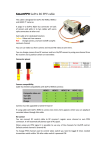
By default middle 5V pin of RCCC CH1 cable is not connected to
CH2 and CH3 connector middle pins to avoid short circuit.
In order to power servos connected to CH2 and CH3, you need to
solder together pads of solder jumper shown in picture under
board.
4