1
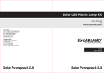
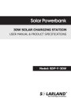
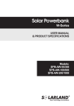
Solarland Grid Connect Solar Kits
User Manual
On-grid Solar Power System
Contents
1. Introduction
Page1
2. How your Solarland Solar Power System Works
Page1
3. System Performance
Page2
4. Safety
Page2
5. Inverter Operations (Samil)
Page4
6. Inverter Operations (EverSolar)
Page6
7. System Maintenance Timetable
Page8
8. Warranty Terms and Conditions
Page8
9. System Drawings
Page11
Warranty Card
Back Cover
1. Introduction
Thank you for placing confidence in Solarland and congratulations on the installation of your new solar power
system. Our Solar Kits have been designed to provide flexibility of use and ease of installation and are designed
to meet standards and to perform in Australian conditions.
These operating instructions describes the operation of Solarland’s various kits. Invariably, the only major
difference between systems will be the amount of solar panels on your roof and the type of inverter used. For
your ease of reference, we have included in this manual a simple overview of inverter operations for both the
inverters we use in our kits. For more information and troubleshooting please see the inverter operations manual
that is supplied with your inverter. You can also view your system diagram in Appendix A.
This documentation is intended for the operator of the system. Information provided in this document is primarily
related to the operation of the unit, display and safety instructions. Be sure to read this manual and the inverter
manual carefully before using. If you encounter any problems during operation of this unit, first check this manual
before contacting your dealer. You should retain this manual and the inverter manuals for trouble shooting in the
future.
2. How your Solarland Solar Power System Works
Solar electricity generation works by converting energy from the sun, in the form of light, into electricity. An
overview of the system is provided in the diagrams on the following page.
Solar modules contain multiple numbers of solar cells encased in a durable casing. Toughened glass is used to
cover and protect the solar cells and an anti reflective coating is used to minimize light reflection from the
surface.
A DC protection breaker is installed on your roof, this breaker enables one to isolate the solar panels from the
rest of the house by disconnecting them from the inverter.
The inverter converts DC electricity produced from the solar panels to AC electricity which is the type of
electricity you use in your house and can be fed into the electricity grid.
In between your inverter and the meter box, we include another AC and DC protection circuit, enabling one to
disconnect the DC current coming from your panels into the inverter or the AC current coming out of the
inverter into the meter box.
1
On-grid Solar Power System
3. System Performance
Your solar system will generate different amounts of electricity depending on your location, the amount of
sunlight, the array angle and direction, and whether there is any shading on your panels at any point during the
day. Weather on a day to day and season to season basis will dramatically effect the output of your systems.
On average, you can expect the following electricity production, measured in kWh.
1.5kW Kit
(kWh per)
Location
Sydney
Melbourne
Brisbane
Adelaide
Perth
Darwin
Canberra
year
2164
1997
2330
2330
2441
2441
2386
day
5.9
5.5
6.4
6.4
6.7
6.7
6.5
1.5kW Kit
(kWh per)
Location
Sydney
Melbourne
Brisbane
Adelaide
Perth
Darwin
Canberra
year
2114
1951
2277
2277
2385
2385
2331
day
5.8
5.3
6.2
6.2
6.5
6.5
6.4
SOLARLAND MONO-CRYSTILLINE KITS
Estimated average power production from the
1.9kW Kit
2.3kW Kit
3.0kW Kit
3.99kW Kit
4.9kW Kit
(kWh per)
(kWh per)
(kWh per)
(kWh per)
(kWh per)
year
2705
2497
2913
2913
3051
3051
2982
day
7.4
6.8
8.0
8.0
8.4
8.4
8.2
year
3246
2996
3495
3495
3662
3662
3578
day
8.9
8.2
9.6
9.6
10.0
10.0
9.8
year
4327
3995
4660
4660
4882
4882
4771
day
11.9
10.9
12.8
12.8
13.4
13.4
13.1
year
5680
5243
6117
6117
6408
6408
6262
day
15.6
14.4
16.8
16.8
17.6
17.6
17.2
year
7032
6491
7573
7573
7934
7934
7753
day
19.3
17.8
20.7
20.7
21.7
21.7
21.2
SOLARLAND POLY-CRYSTILLINE KITS
Estimated average power production from the
2.0kW Kit
2.3kW Kit
3.0kW Kit
4.1kW Kit
(kWh per)
(kWh per)
(kWh per)
(kWh per)
year
2947
2720
3173
3173
3324
3324
3249
day
8.1
7.5
8.7
8.7
9.1
9.1
8.9
year
3274
3022
3526
3526
3694
3694
3610
day
9.0
8.3
9.7
9.7
10.1
10.1
9.9
year
4256
3929
4584
4584
4802
4802
4693
day
11.7
10.8
12.6
12.6
13.2
13.2
12.9
year
5893
5440
6347
6347
6649
6649
6498
day
16.1
14.9
17.4
17.4
18.2
18.2
17.8
5.1kW Kit
(kWh per)
year
7303
6741
7864
7864
8239
8239
8052
day
20.0
18.5
21.5
21.5
22.6
22.6
22.1
4.1kW Kit
(kWh per)
year
7203
6649
7757
7757
8126
8126
7942
day
19.7
18.2
21.3
21.3
22.3
22.3
21.8
4. Safety
The following safety instructions are important. They help protect your personal safety and also are intended to
assist you get the optimum performance of your solar system. The safety instructions must NOT be ignored.
Appropriately Licensed Electricians:
The service and maintenance of your solar system must be carried out by a licensed electrical contractor in
strict compliance with the Australian building and electrical safety rules. If you are not a licensed electrical
contractor or a qualified person do not attempt to do any modification and/or maintenance work on the solar
power system. Doing so may put you in danger and may also void component warranties.
Safety Guidelines
Your solar system produces electricity at levels that can be FATAL
if safety measures are not followed. Never ignore safety instructions.
2
a. Never pour cold water on solar module surfaces when the sun is shining and they are hot. Doing so can
shatter the solar module glass. This type of damage will not be covered by the solar module warranty. This
activity could also expose you to the danger of electrocution.
Never walk on the surface of the solar modules. Doing so will damage the solar module and will not be
covered by warranty.
b. Avoid working in the vicinity of the installed solar module area when raining or when the area is still wet.
The installed solar power system generates electricity when exposed to the sun. The generated voltage is
dangerous and can be fatal. The whole surface must be covered by black sheets prior to working on the
system, in order to ensure that no electricity is being generated.
c. Observe all safety signs installed as part of your system.
d. Please note that DC voltages will be present on the solar module side of the inverter even if the isolating
circuit breakers are completely switched off.
Opening, Repair and Modification system components
Do not open any of the components of your solar power system unless you are a qualified licensed electrical
contractor. Any work on the electrical components, such as repairs or modifications, must be carried out by a
licensed electrical contractor.
Shutting down
The solar power system must be shut down before commencing any electrical work on the building. The
licensed electrician must follow the following proceedure to shut down the system, please refer to the system
drawings in Appendix A.
Step 1-Disconnect the utility grid system from the inverter via the AC Grid Disconnection Circuit Breaker
Step 2-Disconnect the DC power to the inverter at the DC side of the inverter via Grid Disconnection Circuit
Breaker;
Step 3- Disconnect the DC power isolation switch on the roof of your house;
Step 4-Disconnect all MC plugs between solar modules to create lower voltage for a safe work environment.
Even when the system has been disconnected, the solar panels will
still produce electricity during daylight hours. Care must be taken.
Fire
Alert your fire department on arrival that you have a solar system. The system should be shut down the system
as far as possible and all circuit breakers must remain off until the fire is extinguished.
Safe work on roofs
If persons are working on your roof, it you must make them aware that there is the possibility of a small, nonlethal electrical charge being present in the base frame and module frames.
Cleaning the solar array
Depending on the roof slope, the solar panels clean themselves during rainy weather. However, a layer of dust
can form if there is a prolonged dry spell. This could reduce the amount of energy produced by the solar power
system.
We do NOT recommend that you climb on the roof to clean the solar panels. Please do not use a high-pressure
cleaner or chemical cleaning product on the surface of the solar panels – use plain water at mains pressure or
less.
DO NOT wash solar panels when they are hot. Avoid washing them in
the middle of the day, and instead, wash them early in the morning or
late in the afternoon.
Heat build-up
Exercise caution when touching the inverter housing. The inverter can become hot during use. Some part of
the Inverter housing become hot during operation, and sometimes the temperature can reach 60°C in normal
operation. Never cover the inverter’s heat sinks or vents when it is in use. Please observe the distances around
the inverter as laid out in the operating instructions.
3
On-grid Solar Power System
Dust formation
Do not allow excessive dust to build up around the inverter. Never touch damaged cables; report the damage
to your installer immediately.
Circuit breaker
Recurrent tripping of the circuit breaker indicates a fault. Please report this fault to your installer immediately.
Inverter display
Regularly check the inverter display and report any malfunctions or warning signals.
Operating instructions
Please refer to the enclosed operating instructions for further safety information on your inverter and
instructions for displaying your system performance data.
Warning Notices
All safety instructions and signs on the installation must be kept visible and in legible condition. If the signs are
removed, please contact your place of purchase to obtain replacements. Do not cover or paint over safety
signs.
Disconnecting Solar Panels
Your electrician must never disconnect DC plugs on the solar modules while the inverter is feeding power into
the grid. Before disconnecting the DC plug you must always switch off the inverter and turn off all AC and DC
isolation switches as explained in the steps above.
5. Inverter Operations (Samil)
The systems that utilized Samil inverters are those Solar Systems of greater than 2.3kW. These systems utilize a
Samil 3kW, 4kW or 5kW depending on your system size. We have provided the basics below for operating the
inverter below – further information can be found in the inverter manual.
The “state” of an inverter lets the user know whether the inverter is outputing electricity to the mains grid. A
summary of the operating states as will be shown on your LCD display are described in the table below. The
“State” display is the default display on your inverter.
LCD Display
Nothing displayed
Operating State
Power off
Description
If the DC input voltage is less than 70V the inverter
will switch off and the display will not work.
“Waiting”
Initialisation and waiting
Input voltage is in-between 70V and 150V where
the inverter is on but in standby mode.
“Checking”
Checking
Input voltage is greater than 150V and the inverter
is checking with the mains grid to connect.
“Normal State”
Operating
The inverter is connected to the mains grid and is
generating electricity.
The Samil inverter’s function key will switch between the various displays. If you press the key once it will move
to the next item in the menu as shown in the diagram below. The menu is continuous and you have to scroll
through by pressing the button multiple times to get to the menu item you wish to view. If you don’t press the key
for about 10 seconds, the inverter will revert back to showing the state information.
4
ETOTAL
Energy Generated since starting/restarting the inverter
ETODAY
Energy generated on the current day
VPV
Present voltage of the solar system
IPV
Present current of the solar system
VAC
Present voltage of the mains grid
FREQ
Present frequency of the mains grid
MODEL
Model of the inverter
VER
Software Version
SET LANGUAGE
Lanugage Setting
RESET ETODAY
Resets the count for energy produced today
5
On-grid Solar Power System
6. Inverter Operations (EverSolar)
The systems that utilized Eversolar inverters are those Solar Systems of less than or equal to 2.3kW. These
systems utilize an EverSolar 1.7 or 2.3kW inverter depending on your system size. We have provided the basics
below for operating the inverter below – further information can be found in the inverter manual.
The EverSolar inverters are equipped with three LED indicators (Green, Yellow and Red) which provide
information about various operating states. When the green light is on, the inverter is operating normally. When
the Red light on it indicates a fault in the system or with the inverter and the LCD display will provide some
information on the fault that we have provided in a table after the following figure. The Yellow indicator shows that
the inverter is communicating with other devices if you have set up the inverter to a personal computer for
example.
Function Key
Green LED Indicator (Normal)
Red LED Indicator (Fault)
Yellow LED Indicator (Communication)
The “state” of an inverter lets the user know whether the inverter is outputing electricity to the mains grid. A
summary of the operating states as will be shown on your LCD display are described in the table below. The
“State” display is the default display on your inverter.
LCD Display
Nothing displayed
Operating State
Power off
Description
If the DC input voltage is less than 70V the inverter
will switch off and the display will not work.
“Waiting”
Initialisation and waiting
Input voltage is in-between 70V and 150V where
the inverter is on but in standby mode.
“Reconnect”
Reconnecting
Voltage has risen above 150V and the inverter is
reconnecting.
“Checking”
Checking
Input voltage is greater than 150V and the inverter
is checking with the mains grid to connect.
“Normal”
Operating
The inverter is connected to the mains grid and is
generating electricity.
The Eversolar inverter’s function key will switch between the various displays. If you press the key once it will
move to the next item in the menu as shown in the diagram below. The menu is continuous and you have to scroll
through by pressing the button multiple times to get to the menu item you wish to view. If you don’t press the key
for about 10 seconds, the inverter will revert back to showing the state information.
6
E-TODAY
Energy generated on the current day
E-TOTAL
Energy Generated since starting/restarting the inverter
VPV
Present voltage of the solar system
IPV
Present current of the solar system
IAC
Present current of the mains grid
FREQ
Present frequency of the mains grid
MODEL
Model of the inverter
VER
Software Version
SET LANGUAGE
Lanugage Setting
VAC
Mains grid voltage
7
On-grid Solar Power System
7. System Maintenance Timetable
Once a fortnight:
Check inverter and meter displays to ensure operating status is normal and that the energy production is not
lower than expected.
Once every three months
Check the array for shading during the middle of the day, ideally between 10am and 4pm. Surrounding trees
may have grown since the solar system was installed, and may need to be trimmed.
Check your electricity bill to ensure you are being credited for energy generated by your solar power system.
The easiest way to do this is to compare your current bill with the bill for the same period last year. The bill
should show fewer kilowatt hours being consumed.
If not, you may have:
a. Bought any new appliances or made changes to your lifestyle that may mean you are using more energy than
in the same period last year?
b. Your solar power system generates less energy in winter and more in summer. If it is currently winter, the
solar power system may not make a significant difference to your bill.
c. If you have not had your solar power system for the full quarter, it may not have generated enough energy to
make a significant difference to your bill.
If none of the above explains the difference, and you are still concerned, call your system installer and ask for
assistance to test the inverter and find out how much energy you have generated. Then, if required, contact
your electricity retailer and check that their billing system includes energy generated by your solar power
system.
Once a year:
The installer of your Solarland power system or a qualified electrician should carry out an annual maintenance
check.
8. Warranty Terms and Conditions
Inclusive within this warranty are all terms, conditions and rights provided to the end consumer under Australian
Law, and as are described in the Trade Practices Act 1974 (Cth) and any other statutory rights to which the
purchaser may be entitles subject to meeting the terms and conditions as set out below.
Solarland Australia warrants the Solar Kit against defects in manufacturing, performance and any defects subject
to the following conditions. The Solar Kit is comprised of a photovoltaic solar panel array, mounting brackets and
racking, direct current to alternating current inverter, enclosures, circuit breakers, cabling and wiring.
Product Types & Warranty Term
Solarland Australia warrants that the Solar Kit components shall be fee of manufacturing defects and shall
perform in accordance with their specifications. Details are provided below on product types:
SolarlandTM On-Grid Panels
Solarland Australia warrants that a solar panel provided as part of the Solar Kit shall provide a minimum of 90%
of the nominated DC power output of the panel for a period of 10 years from the date of sale. Further, the panel
shall provide a minimum of 80% of the nominated DC power output capacity of the panel for a period of twenty
five years from the date of sale. Panel workmanship is warranted for a period of ten years.
Inverters
Solarland Australia provides a local service point for all the inverters that it supplies in Solarland’s Solar Kits.
Inverters are provided with a manufactures warranty for 5 years. The customer must complete the inverter
warranty card supplied with the inverter must and send it to the address specified by the inverter manufacturer.
Talk to the dealer from who you purchased the system to find out about extending your inverter warranty to 10
years.
Balance of System
All other components (enclosures, cabling, breakers, racking system) are covered by Solarland Australia for a
period of 5 years.
Performance Testing
Performance of system components shall be deemed and tested as set out in the testing procedures below.
During the Warranty Period, testing of the performance of a system shall be conducted at all times in accordance
with the following procedure:
8
Level 1 performance testing: If a system is producing zero electricity, the customer will first contact the place
of purchase or the installer to action testing*1 . The Seller or Installer will then co-ordinate a visit to the site to
determine the cause of the fault. If the fault is reasonably determined to be due to manufacturing, faulty
material or installation, the fault will be rectified at no cost to the customer. If determined to be caused by
external sources, rectification will be at the customers expense as set out below.
Level 2 performance testing - If the customer believes the system to be underperforming, the customer will
contact the Seller or Installer get information on recording and completing a Performance Log for the system*.
The Seller or Installer will assess Performance Log Form based on installation parameters, and reasonably
expected performance under specific conditions applicable to the installation location. If Solarland Australia
determines the Solar Kit to be performing at lower than expected capacity, then a visit will be made by a
technician to the installation address to determine the cause of the fault. If the fault is reasonably determined
to be due to manufacturing, faulty material or installation, the fault will be rectified at no cost to the customer. If
determined to be caused by external sources, rectification will be at the customer’s expense as set out below.
Level 3 Performance Testing - If the customer requires performance testing to be carried out in respect of the
Solar Kit which requires materials to be tested by any external third party, then any costs associated with the
dismantling of the Solar Kit component, transport and labour shall be paid for in full by the customer. If during
the warranty period, testing determine that the component is not performing within specifications, then the
testing fees, transport and labour shall be waived or reimbursed, and testing provided at no cost to the
customer. If any performance outside the specifications is determined to be the result of external factors
including but not limited to the exceptions below, then any testing fees, transportation and labour shall be
immediately payable by the customer.
Fees - Expenses incurred in respect of testing shall be determined as follows (ex-GST):
Level 1 performance testing fee - $300
Level 2 performance testing fee- $500
Level 3 performance testing - AT COST
Transport and labour costs - AT COST
Warranty Exclusions and Exceptions
Notwithstanding any statutory obligations to the contrary:
Under no circumstances shall Solarland Australia be liable for any replacement of materials:
Where the Warranty Card has not been fully completed and a legible Tax Invoice for purchase are not
presented at the time of warranty claim.
Where there is any evidence of tampering with the installation by a third party that is not an approved
technician of Solarland Australia.
Damage, malfunctions or service failures are caused by misuse, abuse or negligent acts.
Where any fault or defect is due to any solid matter on the panels
Due to any Act of God (power failure surges, lightening strike, pest damage, storm, fire or other natural
occurrence) whatsoever or other events outside Solarland Australia’s reasonable control.
Where the serial numbers on the Solar Kit components have been altered, removed or rendered illegible.
Replacement components will carry the balance of warranty from the original date of purchase, not a full new
warranty.
This Warranty specifically excludes any and all consequential losses suffered whatsoever by the customer
including but not limited to replacement of goods or materials, due to any direct or indirect consequence of power
surge, water leak or other factor determined or otherwise associated with the installation and performance of the
Solar Kit
This Warranty excludes replacement of panels due to breakage of glass after installation of the panels, which
replacement would be covered by standard household insurances.
Performance warranty excludes any reduction in capacity or performance degradation due to incorrect
installation, or installation in non ideal locations or directions, or subject to shading. Any Solar Kit installed under
conditions different to the nominal output testing conditions shall have a de-rate factor applied in accordance with
the installation conditions.
Installation warranties shall be specifically excluded if the installation is undertaken by an installer other than as
recommended by Solarland Australia.
1
*If the customer can not contact the Seller or Installer, the customer can contact Solarland Australia via email at [email protected] with a scanned copy
of the installation documentation and receipt that shows the place and data of purchase and the name and contact details of the installer. The Customer should
include in the subject of the email the installation address – Subject: Warranty Claim - <insert installation address>.
9
On-grid Solar Power System
Validity Requirements
For this Solarland Australia Warranty to be valid, the customer must:
Have the Solar Kit installed in accordance with Australian Standard AS4777 by a licensed electrician who is
approved and accredited by the Clean Energy Council.
Use Solar Kit Components supplied by Solarland Australia only
Provide a Tax Invoice for the system purchase and a singed system warranty card including date of
installation, and signed by the installer when making any claim whatsoever.
Limitation of Liability
The Warranty terms and conditions here to attached shall in no circumstances create a liability in excess of the
amount paid by the customer for the Solar Kit.
Solarland Australia makes no warranties, express or implied, other than the warranties made herein, and
specifically disclaims any warranty of merchantability or fitness for a particular purpose. Any warranties implied
by, including those of merchantability and fitness for particular purpose, which are not effectively excluded herein
are limited in duration to the terms stated in this warranty.
Solarland Australia is not responsible for any special incidental consequential or punitive damages arising from
the use or loss of the use of or failure of your product to perform as warranted.
Solarland Australia, to the extent required by applicable law, nothing in this warranty shall operate or shall be
construed to operate so as to exclude or restrict the liability of Solarland Australia for the death or personal injury
caused to the purchaser by reason of the negligence of Solarland Australia or its servants, employees or agents.
Any claim or dispute arising under or in connection with this warranty must be brought in the courts of the State of
New South Wales, Australia.
10
9. System Drawings
MONO 1.5kW
IP66 Enclosure
500VDC DP MCB
IP65 Enclosure
500VDC DP MCB
+
-
+
PV PANEL
190W 24V
Vmp = 36.80V
Imp = 5.16A
Voc = 45.0V
Isc = 5.56A
PV PANEL
190W 24V
Max System Voltage = 1000VDC
Vmp = 36.80V
Imp = 5.16A
Voc = 45.0V
Isc = 5.56A
PV PANEL
190W 24V
Max System Voltage = 1000VDC
Vmp = 36.80V
Imp = 5.16A
Voc = 45.0V
Isc = 5.56A
PV PANEL
190W 24V
Vmp = 36.80V
Imp = 5.16A
Voc = 45.0V
Isc = 5.56A
PV PANEL
190W 24V
Max System Voltage = 1000VDC
PV PANEL
190W 24V
Vmp = 36.80V
Imp = 5.16A
Voc = 45.0V
Isc = 5.56A
PV PANEL
190W 24V
Vmp = 36.80V
Imp = 5.16A
Voc = 45.0V
Isc = 5.56A
Max System Voltage = 1000VDC
PV PANEL
190W 24V
Max System Voltage = 1000VDC
Max System Voltage = 1000VDC
Vmp = 36.80V
Imp = 5.16A
Voc = 45.0V
Isc = 5.56A
ROOF
Max System Voltage = 1000VDC
NEUTRAL
450VAC DP MCB
IP65 Enclosure
Vmp = 36.80V
Imp = 5.16A
Voc = 45.0V
Isc = 5.56A
IP65
MAX DC INPUT 450VDC
18A
1800W
L2
L1
Max System Voltage = 1000VDC
DC
1.5kW INVERTER
AC
ENCLOSURE
to solar ready meter
NAME
SIGNATURE
UNLESS OTHERWISE SPECIFIED: FINISH:
DIMENSIONS ARE IN MILLIMETERS
SURFACE FINISH:
TOLERANCES:
LINEAR:
ANGULAR:
DRAWN
CHK'D
Q.A
MFG
APPV'D
DATE
MATERIAL:
WEIGHT:
DO NOT SCALE DRAWING
REVISION
SHEET 1 OF 1
MONO_1.5kW
A1
SYSTEM SPECIFICATIONS
TITLE:
Wmp - 1520W
Vmp - 288VDC
Imp - 5.16A
1 string
DEBUR AND
BREAK SHARP
EDGES
DWG NO.
SCALE:1:1
11
On-grid Solar Power System
MONO 1.5kW with earthing
IP66 Enclosure
500VDC DP MCB
IP65 Enclosure
500VDC DP MCB
+
-
+
PV PANEL
190W 24V
PV PANEL
190W 24V
Max System Voltage = 1000VDC
Vmp = 36.80V
Imp = 5.16A
Voc = 45.0V
Isc = 5.56A
PV PANEL
190W 24V
Max System Voltage = 1000VDC
Vmp = 36.80V
Imp = 5.16A
Voc = 45.0V
Isc = 5.56A
PV PANEL
190W 24V
Vmp = 36.80V
Imp = 5.16A
Voc = 45.0V
Isc = 5.56A
PV PANEL
190W 24V
Vmp = 36.80V
Imp = 5.16A
Voc = 45.0V
Isc = 5.56A
PV PANEL
190W 24V
Max System Voltage = 1000VDC
Vmp = 36.80V
Imp = 5.16A
Voc = 45.0V
Isc = 5.56A
Vmp = 36.80V
Imp = 5.16A
Voc = 45.0V
Isc = 5.56A
PV PANEL
190W 24V
Max System Voltage = 1000VDC
Max System Voltage = 1000VDC
PV PANEL
190W 24V
Vmp = 36.80V
Imp = 5.16A
Voc = 45.0V
Isc = 5.56A
Max System Voltage = 1000VDC
Max System Voltage = 1000VDC
ROOF
Vmp = 36.80V
Imp = 5.16A
Voc = 45.0V
Isc = 5.56A
450VAC DP MCB
IP65 Enclosure
Max System Voltage = 1000VDC
IP65
MAX DC INPUT 450VDC
18A
1800W
L1
N
ENCLOSURE
DC
1.5kW INVERTER
AC
to solar ready meter
NAME
SIGNATURE
UNLESS OTHERWISE SPECIFIED: FINISH:
DIMENSIONS ARE IN MILLIMETERS
SURFACE FINISH:
TOLERANCES:
LINEAR:
ANGULAR:
DRAWN
CHK'D
Q.A
MFG
APPV'D
DATE
MATERIAL:
WEIGHT:
DO NOT SCALE DRAWING
REVISION
A1
SYSTEM SPECIFICATIONS
TITLE:
Wmp - 1520W
Vmp - 288VDC
Imp - 5.16A
1 string
DEBUR AND
BREAK SHARP
EDGES
SHEET 1 OF 1
MONO_1.5kWv4
DWG NO.
SCALE:1:1
12
MONO 2.3kW
IP66 Enclosure
500VDC DP MCB
IP65 Enclosure
500VDC DP MCB
+
-
+
Vmp = 36.80V
Imp = 5.16A
Voc = 45.0V
Isc = 5.56A
PV PANEL
190W 24V
PV PANEL
190W 24V
Vmp = 36.80V
Imp = 5.16A
Voc = 45.0V
Isc = 5.56A
PV PANEL
190W 24V
Max System Voltage = 1000VDC
Vmp = 36.80V
Imp = 5.16A
Voc = 45.0V
Isc = 5.56A
PV PANEL
190W 24V
Vmp = 36.80V
Imp = 5.16A
Voc = 45.0V
Isc = 5.56A
Max System Voltage = 1000VDC
Vmp = 36.80V
Imp = 5.16A
Voc = 45.0V
Isc = 5.56A
PV PANEL
190W 24V
PV PANEL
190W 24V
Max System Voltage = 1000VDC
Max System Voltage = 1000VDC
Vmp = 36.80V
Imp = 5.16A
Voc = 45.0V
Isc = 5.56A
PV PANEL
190W 24V
Vmp = 36.80V
Imp = 5.16A
Voc = 45.0V
Isc = 5.56A
Max System Voltage = 1000VDC
Vmp = 36.80V
Imp = 5.16A
Voc = 45.0V
Isc = 5.56A
PV PANEL
190W 24V
PV PANEL
190W 24V
Max System Voltage = 1000VDC
Max System Voltage = 1000VDC
Vmp = 36.80V
Imp = 5.16A
Voc = 45.0V
Isc = 5.56A
PV PANEL
190W 24V
Vmp = 36.80V
Imp = 5.16A
Voc = 45.0V
Isc = 5.56A
Max System Voltage = 1000VDC
PV PANEL
190W 24V
PV PANEL
190W 24V
Max System Voltage = 1000VDC
DRAWN
NAME
SIGNATURE
UNLESS OTHERWISE SPECIFIED: FINISH:
DIMENSIONS ARE IN MILLIMETERS
SURFACE FINISH:
TOLERANCES:
LINEAR:
ANGULAR:
to solar ready meter
Max System Voltage = 1000VDC
Vmp = 36.80V
Imp = 5.16A
Voc = 45.0V
Isc = 5.56A
ROOF
Max System Voltage = 1000VDC
NEUTRAL
450VAC DP MCB
IP65 Enclosure
Vmp = 36.80V
Imp = 5.16A
Voc = 45.0V
Isc = 5.56A
IP65
MAX DC INPUT 500VDC
18A
2300W
L2
L1
Max System Voltage = 1000VDC
DC
2.0kW INVERTER
AC
ENCLOSURE
CHK'D
Q.A
MFG
APPV'D
DATE
MATERIAL:
WEIGHT:
DO NOT SCALE DRAWING
REVISION
SHEET 1 OF 1
MONO_2.3kW
A1
SYSTEM SPECIFICATIONS
TITLE:
Wmp - 2280W
Vmp - 432VDC
Imp - 5.16A
1 string
DEBUR AND
BREAK SHARP
EDGES
DWG NO.
SCALE:1:1
13
On-grid Solar Power System
MONO 3.0kW
IP66 Enclosure
500VDC DP MCB
IP66 Enclosure
500VDC DP MCB
+
-
IP65 Enclosure
500VDC DP MCB
Vmp = 36.80V
Imp = 5.16A
Voc = 45.0V
Isc = 5.56A
PV PANEL
190W 24V
Vmp = 36.80V
Imp = 5.16A
Voc = 45.0V
Isc = 5.56A
PV PANEL
190W 24V
Max System Voltage = 1000VDC
Vmp = 36.80V
Imp = 5.16A
Voc = 45.0V
Isc = 5.56A
PV PANEL
190W 24V
Max System Voltage = 1000VDC
Vmp = 36.80V
Imp = 5.16A
Voc = 45.0V
Isc = 5.56A
PV PANEL
190W 24V
Max System Voltage = 1000VDC
Vmp = 36.80V
Imp = 5.16A
Voc = 45.0V
Isc = 5.56A
PV PANEL
190W 24V
PV PANEL
190W 24V
Max System Voltage = 1000VDC
Max System Voltage = 1000VDC
Vmp = 36.80V
Imp = 5.16A
Voc = 45.0V
Isc = 5.56A
PV PANEL
190W 24V
Vmp = 36.80V
Imp = 5.16A
Voc = 45.0V
Isc = 5.56A
Max System Voltage = 1000VDC
Vmp = 36.80V
Imp = 5.16A
Voc = 45.0V
Isc = 5.56A
PV PANEL
190W 24V
PV PANEL
190W 24V
Max System Voltage = 1000VDC
Max System Voltage = 1000VDC
Vmp = 36.80V
Imp = 5.16A
Voc = 45.0V
Isc = 5.56A
PV PANEL
190W 24V
PV PANEL
190W 24V
Vmp = 36.80V
Imp = 5.16A
Voc = 45.0V
Isc = 5.56A
Max System Voltage = 1000VDC
Vmp = 36.80V
Imp = 5.16A
Voc = 45.0V
Isc = 5.56A
PV PANEL
190W 24V
PV PANEL
190W 24V
Max System Voltage = 1000VDC
ROOF
Vmp = 36.80V
Imp = 5.16A
Voc = 45.0V
Isc = 5.56A
IP65 Enclosure
450VAC DP MCB
to solar ready meter
Max System Voltage = 1000VDC
IP65
MAX DC INPUT 550VDC
17.5A
3480W
L2
SIGNATURE
TITLE:
-
+
REVISION
SHEET 1 OF 1
MONO_3.0kW
DO NOT SCALE DRAWING
Wmp - 3040W
Vmp - 288VDC
Imp - 10.32A
2 string
DEBUR AND
BREAK SHARP
EDGES
DWG NO.
SCALE:1:1
A1
SYSTEM SPECIFICATIONS
Vmp = 36.80V
Imp = 5.16A
Voc = 45.0V
Isc = 5.56A
Max System Voltage = 1000VDC
Vmp = 36.80V
Imp = 5.16A
Voc = 45.0V
Isc = 5.56A
DC
3.3kW INVERTER
AC
NEUTRAL
NAME
UNLESS OTHERWISE SPECIFIED: FINISH:
DIMENSIONS ARE IN MILLIMETERS
SURFACE FINISH:
TOLERANCES:
LINEAR:
ANGULAR:
DRAWN
WEIGHT:
Max System Voltage = 1000VDC
Max System Voltage = 1000VDC
PV PANEL
190W 24V
Max System Voltage = 1000VDC
Vmp = 36.80V
Imp = 5.16A
Voc = 45.0V
Isc = 5.56A
L1
DATE
MATERIAL:
PV PANEL
190W 24V
PV PANEL
190W 24V
Vmp = 36.80V
Imp = 5.16A
Voc = 45.0V
Isc = 5.56A
Max System Voltage = 1000VDC
+
ENCLOSURE
CHK'D
Q.A
MFG
APPV'D
14
MONO 4.0kW
IP66 Enclosure
500VDC DP MCB
IP66 Enclosure
500VDC DP MCB
IP66 Enclosure
500VDC DP MCB
+
-
-
Vmp = 36.80V
Imp = 5.16A
Voc = 45.0V
Isc = 5.56A
PV PANEL
190W 24V
Max System Voltage = 1000VDC
Vmp = 36.80V
Imp = 5.16A
Voc = 45.0V
Isc = 5.56A
PV PANEL
190W 24V
PV PANEL
190W 24V
Max System Voltage = 1000VDC
Vmp = 36.80V
Imp = 5.16A
Voc = 45.0V
Isc = 5.56A
PV PANEL
190W 24V
PV PANEL
190W 24V
Max System Voltage = 1000VDC
Vmp = 36.80V
Imp = 5.16A
Voc = 45.0V
Isc = 5.56A
PV PANEL
190W 24V
PV PANEL
190W 24V
Max System Voltage = 1000VDC
Vmp = 36.80V
Imp = 5.16A
Voc = 45.0V
Isc = 5.56A
PV PANEL
190W 24V
PV PANEL
190W 24V
Max System Voltage = 1000VDC
Vmp = 36.80V
Imp = 5.16A
Voc = 45.0V
Isc = 5.56A
PV PANEL
190W 24V
PV PANEL
190W 24V
Vmp = 36.80V
Imp = 5.16A
Voc = 45.0V
Isc = 5.56A
Max System Voltage = 1000VDC
Vmp = 36.80V
Imp = 5.16A
Voc = 45.0V
Isc = 5.56A
PV PANEL
190W 24V
Max System Voltage = 1000VDC
PV PANEL
190W 24V
Vmp = 36.80V
Imp = 5.16A
Voc = 45.0V
Isc = 5.56A
Vmp = 36.80V
Imp = 5.16A
Voc = 45.0V
Isc = 5.56A
Max System Voltage = 1000VDC
PV PANEL
190W 24V
Max System Voltage = 1000VDC
Vmp = 36.80V
Imp = 5.16A
Voc = 45.0V
Isc = 5.56A
Vmp = 36.80V
Imp = 5.16A
Voc = 45.0V
Isc = 5.56A
Max System Voltage = 1000VDC
PV PANEL
190W 24V
Max System Voltage = 1000VDC
ROOF
-
+
+
DRAWN
NAME
SIGNATURE
UNLESS OTHERWISE SPECIFIED: FINISH:
DIMENSIONS ARE IN MILLIMETERS
SURFACE FINISH:
TOLERANCES:
LINEAR:
ANGULAR:
to solar ready meter
Vmp = 36.80V
Imp = 5.16A
Voc = 45.0V
Isc = 5.56A
Vmp = 36.80V
Imp = 5.16A
Voc = 45.0V
Isc = 5.56A
PV PANEL
190W 24V
450VAC DP MCB
NEUTRAL
Max System Voltage = 1000VDC
Max System Voltage = 1000VDC
Vmp = 36.80V
Imp = 5.16A
Voc = 45.0V
Isc = 5.56A
Vmp = 36.80V
Imp = 5.16A
Voc = 45.0V
Isc = 5.56A
PV PANEL
190W 24V
Max System Voltage = 1000VDC
Max System Voltage = 1000VDC
Vmp = 36.80V
Imp = 5.16A
Voc = 45.0V
Isc = 5.56A
Vmp = 36.80V
Imp = 5.16A
Voc = 45.0V
Isc = 5.56A
PV PANEL
190W 24V
Max System Voltage = 1000VDC
Max System Voltage = 1000VDC
PV PANEL
190W 24V
Vmp = 36.80V
Imp = 5.16A
Voc = 45.0V
Isc = 5.56A
IP65
MAX DC INPUT 550VDC
22.0A
4580W
L2
IP65 Enclosure
Max System Voltage = 1000VDC
DC
4.4kW INVERTER
AC
L1
Vmp = 36.80V
Imp = 5.16A
Voc = 45.0V
Isc = 5.56A
Max System Voltage = 1000VDC
Vmp = 36.80V
Imp = 5.16A
Voc = 45.0V
Isc = 5.56A
PV PANEL
190W 24V
Max System Voltage = 1000VDC
PV PANEL
190W 24V
-
Max System Voltage = 1000VDC
IP65 Enclosure
500VDC DP MCB
+
ENCLOSURE
CHK'D
Q.A
MFG
APPV'D
DATE
MATERIAL:
WEIGHT:
DO NOT SCALE DRAWING
REVISION
A1
SYSTEM SPECIFICATIONS
TITLE:
Wmp - 3990W
Vmp - 252VDC
Imp - 15.48A
3 string
DEBUR AND
BREAK SHARP
EDGES
SHEET 1 OF 1
MONO_4.0kWv4
DWG NO.
SCALE:1:1
15
On-grid Solar Power System
MONO 5.0kW
IP66 Enclosure
500VDC DP MCB
IP66 Enclosure
500VDC DP MCB
IP66 Enclosure
500VDC DP MCB
+
-
-
Vmp = 36.80V
Imp = 5.16A
Voc = 45.0V
Isc = 5.56A
PV PANEL
190W 24V
Max System Voltage = 1000VDC
Vmp = 36.80V
Imp = 5.16A
Voc = 45.0V
Isc = 5.56A
PV PANEL
190W 24V
Max System Voltage = 1000VDC
Vmp = 36.80V
Imp = 5.16A
Voc = 45.0V
Isc = 5.56A
PV PANEL
190W 24V
Max System Voltage = 1000VDC
Vmp = 36.80V
Imp = 5.16A
Voc = 45.0V
Isc = 5.56A
PV PANEL
190W 24V
Max System Voltage = 1000VDC
Vmp = 36.80V
Imp = 5.16A
Voc = 45.0V
Isc = 5.56A
PV PANEL
190W 24V
Max System Voltage = 1000VDC
Vmp = 36.80V
Imp = 5.16A
Voc = 45.0V
Isc = 5.56A
PV PANEL
190W 24V
Max System Voltage = 1000VDC
Vmp = 36.80V
Imp = 5.16A
Voc = 45.0V
Isc = 5.56A
PV PANEL
190W 24V
Max System Voltage = 1000VDC
Vmp = 36.80V
Imp = 5.16A
Voc = 45.0V
Isc = 5.56A
PV PANEL
190W 24V
Vmp = 36.80V
Imp = 5.16A
Voc = 45.0V
Isc = 5.56A
PV PANEL
190W 24V
PV PANEL
190W 24V
PV PANEL
190W 24V
PV PANEL
190W 24V
PV PANEL
190W 24V
PV PANEL
190W 24V
PV PANEL
190W 24V
Max System Voltage = 1000VDC
Vmp = 36.80V
Imp = 5.16A
Voc = 45.0V
Isc = 5.56A
PV PANEL
190W 24V
Max System Voltage = 1000VDC
Vmp = 36.80V
Imp = 5.16A
Voc = 45.0V
Isc = 5.56A
PV PANEL
190W 24V
PV PANEL
190W 24V
Vmp = 36.80V
Imp = 5.16A
Voc = 45.0V
Isc = 5.56A
Vmp = 36.80V
Imp = 5.16A
Voc = 45.0V
Isc = 5.56A
Max System Voltage = 1000VDC
PV PANEL
190W 24V
Max System Voltage = 1000VDC
Vmp = 36.80V
Imp = 5.16A
Voc = 45.0V
Isc = 5.56A
Vmp = 36.80V
Imp = 5.16A
Voc = 45.0V
Isc = 5.56A
Max System Voltage = 1000VDC
PV PANEL
190W 24V
Max System Voltage = 1000VDC
Vmp = 36.80V
Imp = 5.16A
Voc = 45.0V
Isc = 5.56A
Vmp = 36.80V
Imp = 5.16A
Voc = 45.0V
Isc = 5.56A
Max System Voltage = 1000VDC
PV PANEL
190W 24V
Max System Voltage = 1000VDC
Vmp = 36.80V
Imp = 5.16A
Voc = 45.0V
Isc = 5.56A
Vmp = 36.80V
Imp = 5.16A
Voc = 45.0V
Isc = 5.56A
Max System Voltage = 1000VDC
PV PANEL
190W 24V
Max System Voltage = 1000VDC
Vmp = 36.80V
Imp = 5.16A
Voc = 45.0V
Isc = 5.56A
PV PANEL
190W 24V
Vmp = 36.80V
Imp = 5.16A
Voc = 45.0V
Isc = 5.56A
Max System Voltage = 1000VDC
PV PANEL
190W 24V
Max System Voltage = 1000VDC
Vmp = 36.80V
Imp = 5.16A
Voc = 45.0V
Isc = 5.56A
PV PANEL
190W 24V
Vmp = 36.80V
Imp = 5.16A
Voc = 45.0V
Isc = 5.56A
ROOF
Max System Voltage = 1000VDC
450VAC DP MCB
IP65 Enclosure
Vmp = 36.80V
Imp = 5.16A
Voc = 45.0V
Isc = 5.56A
IP65
MAX DC INPUT 550VDC
26.0A
5200W
L2
NEUTRAL
-
+
+
DRAWN
NAME
SIGNATURE
UNLESS OTHERWISE SPECIFIED: FINISH:
DIMENSIONS ARE IN MILLIMETERS
SURFACE FINISH:
TOLERANCES:
LINEAR:
ANGULAR:
to solar ready meter
Max System Voltage = 1000VDC
DC
5.1kW INVERTER
AC
L1
Vmp = 36.80V
Imp = 5.16A
Voc = 45.0V
Isc = 5.56A
-
Max System Voltage = 1000VDC
Max System Voltage = 1000VDC
Max System Voltage = 1000VDC
Max System Voltage = 1000VDC
PV PANEL
190W 24V
Vmp = 36.80V
Imp = 5.16A
Voc = 45.0V
Isc = 5.56A
Max System Voltage = 1000VDC
PV PANEL
190W 24V
Vmp = 36.80V
Imp = 5.16A
Voc = 45.0V
Isc = 5.56A
Max System Voltage = 1000VDC
IP65 Enclosure
500VDC DP MCB
+
ENCLOSURE
CHK'D
Q.A
MFG
APPV'D
DATE
MATERIAL:
WEIGHT:
DO NOT SCALE DRAWING
REVISION
A1
SYSTEM SPECIFICATIONS
TITLE:
Wmp - 5130W
Vmp - 324VDC
Imp - 15.48A
3 string
DEBUR AND
BREAK SHARP
EDGES
SHEET 1 OF 1
MONO_5.0kWv4
DWG NO.
SCALE:1:1
16
POLY 1.5kW
IP66 Enclosure
500VDC DP MCB
IP65 Enclosure
500VDC DP MCB
+
+
Vmp = 34.80V
Imp = 3.87A
Voc = 43.4V
Isc = 4.25A
PV PANEL
135W 24V
Max System Voltage = 1000VDC
Vmp = 34.80V
Imp = 3.87A
Voc = 43.4V
Isc = 4.25A
PV PANEL
135W 24V
Max System Voltage = 1000VDC
Vmp = 34.80V
Imp = 3.87A
Voc = 43.4V
Isc = 4.25A
PV PANEL
135W 24V
Max System Voltage = 1000VDC
Vmp = 34.80V
Imp = 3.87A
Voc = 43.4V
Isc = 4.25A
PV PANEL
135W 24V
Vmp = 34.80V
Imp = 3.87A
Voc = 43.4V
Isc = 4.25A
PV PANEL
135W 24V
Max System Voltage = 1000VDC
Vmp = 34.80V
Imp = 3.87A
Voc = 43.4V
Isc = 4.25A
PV PANEL
135W 24V
DRAWN
NAME
SIGNATURE
UNLESS OTHERWISE SPECIFIED: FINISH:
DIMENSIONS ARE IN MILLIMETERS
SURFACE FINISH:
TOLERANCES:
LINEAR:
ANGULAR:
to solar ready meter
Max System Voltage = 1000VDC
Vmp = 34.80V
Imp = 3.87A
Voc = 43.4V
Isc = 4.25A
PV PANEL
135W 24V
Max System Voltage = 1000VDC
Vmp = 34.80V
Imp = 3.87A
Voc = 43.4V
Isc = 4.25A
ROOF
Max System Voltage = 1000VDC
PV PANEL
135W 24V
Max System Voltage = 1000VDC
Vmp = 34.80V
Imp = 3.87A
Voc = 43.4V
Isc = 4.25A
Vmp = 34.80V
Imp = 3.87A
Voc = 43.4V
Isc = 4.25A
450VAC DP MCB
NEUTRAL
Max System Voltage = 1000VDC
L1
L2
IP65 Enclosure
PV PANEL
135W 24V
Max System Voltage = 1000VDC
PV PANEL
135W 24V
IP65
MAX DC INPUT 450VDC
18A
1800W
Max System Voltage = 1000VDC
Vmp = 34.80V
Imp = 3.87A
Voc = 43.4V
Isc = 4.25A
-
PV PANEL
135W 24V
DC
1.5kW INVERTER
AC
ENCLOSURE
CHK'D
Q.A
MFG
APPV'D
DATE
MATERIAL:
WEIGHT:
DO NOT SCALE DRAWING
REVISION
SHEET 1 OF 1
POLY_1.5kW
A1
SYSTEM SPECIFICATIONS
TITLE:
Wmp - 1485W
Vmp - 396DC
Imp - 3.87A
1 string
DEBUR AND
BREAK SHARP
EDGES
DWG NO.
SCALE:1:1
17
On-grid Solar Power System
POLY 2.3kW
IP66 Enclosure
500VDC DP MCB
IP65 Enclosure
500VDC DP MCB
+
DC
+
-
IP65
MAX DC INPUT 500VDC
18A
2300W
2.0kW INVERTER
AC
Max System Voltage = 1000VDC
Vmp = 29.20V
Imp = 7.87A
Voc = 36.5V
Isc = 8.65A
PV PANEL
230W 20V
Vmp = 29.20V
Imp = 7.87A
Voc = 36.5V
Isc = 8.65A
PV PANEL
230W 20V
Max System Voltage = 1000VDC
Vmp = 29.20V
Imp = 7.87A
Voc = 36.5V
Isc = 8.65A
PV PANEL
230W 20V
Max System Voltage = 1000VDC
Vmp = 29.20V
Imp = 7.87A
Voc = 36.5V
Isc = 8.65A
PV PANEL
230W 20V
Max System Voltage = 1000VDC
Vmp = 29.20V
Imp = 7.87A
Voc = 36.5V
Isc = 8.65A
Max System Voltage = 1000VDC
PV PANEL
230W 20V
Vmp = 29.20V
Imp = 7.87A
Voc = 36.5V
Isc = 8.65A
PV PANEL
230W 20V
Max System Voltage = 1000VDC
Vmp = 29.20V
Imp = 7.87A
Voc = 36.5V
Isc = 8.65A
PV PANEL
230W 20V
DRAWN
NAME
SIGNATURE
UNLESS OTHERWISE SPECIFIED: FINISH:
DIMENSIONS ARE IN MILLIMETERS
SURFACE FINISH:
TOLERANCES:
LINEAR:
ANGULAR:
to solar ready meter
Max System Voltage = 1000VDC
Vmp = 29.20V
Imp = 7.87A
Voc = 36.5V
Isc = 8.65A
PV PANEL
230W 20V
Max System Voltage = 1000VDC
Vmp = 29.20V
Imp = 7.87A
Voc = 36.5V
Isc = 8.65A
PV PANEL
230W 20V
ROOF
Max System Voltage = 1000VDC
Vmp = 29.20V
Imp = 7.87A
Voc = 36.5V
Isc = 8.65A
Max System Voltage = 1000VDC
NEUTRAL
450VAC DP MCB
IP65 Enclosure
PV PANEL
230W 20V
L1
L2
ENCLOSURE
CHK'D
Q.A
MFG
APPV'D
DATE
MATERIAL:
WEIGHT:
DO NOT SCALE DRAWING
REVISION
SHEET 1 OF 1
POLY_2.3kW
A1
SYSTEM SPECIFICATIONS
TITLE:
Wmp - 2300W
Vmp - 300DC
Imp - 7.87A
1 string
DEBUR AND
BREAK SHARP
EDGES
DWG NO.
SCALE:1:1
18
POLY 3.0kW
IP66 Enclosure
500VDC DP MCB
+
Max System Voltage = 1000VDC
Vmp = 29.20V
Imp = 7.87A
Voc = 36.5V
Isc = 8.65A
PV PANEL
230W 20V
IP65 Enclosure
500VDC DP MCB
-
+
Max System Voltage = 1000VDC
Vmp = 29.20V
Imp = 7.87A
Voc = 36.5V
Isc = 8.65A
PV PANEL
230W 20V
Max System Voltage = 1000VDC
Vmp = 29.20V
Imp = 7.87A
Voc = 36.5V
Isc = 8.65A
PV PANEL
230W 20V
Vmp = 29.20V
Imp = 7.87A
Voc = 36.5V
Isc = 8.65A
PV PANEL
230W 20V
Max System Voltage = 1000VDC
Vmp = 29.20V
Imp = 7.87A
Voc = 36.5V
Isc = 8.65A
PV PANEL
230W 20V
Max System Voltage = 1000VDC
Vmp = 29.20V
Imp = 7.87A
Voc = 36.5V
Isc = 8.65A
PV PANEL
230W 20V
Max System Voltage = 1000VDC
Vmp = 29.20V
Imp = 7.87A
Voc = 36.5V
Isc = 8.65A
Max System Voltage = 1000VDC
PV PANEL
230W 20V
Vmp = 29.20V
Imp = 7.87A
Voc = 36.5V
Isc = 8.65A
PV PANEL
230W 20V
Max System Voltage = 1000VDC
Vmp = 29.20V
Imp = 7.87A
Voc = 36.5V
Isc = 8.65A
PV PANEL
230W 20V
DRAWN
NAME
SIGNATURE
UNLESS OTHERWISE SPECIFIED: FINISH:
DIMENSIONS ARE IN MILLIMETERS
SURFACE FINISH:
TOLERANCES:
LINEAR:
ANGULAR:
to solar ready meter
Max System Voltage = 1000VDC
Vmp = 29.20V
Imp = 7.87A
Voc = 36.5V
Isc = 8.65A
PV PANEL
230W 20V
Max System Voltage = 1000VDC
Vmp = 29.20V
Imp = 7.87A
Voc = 36.5V
Isc = 8.65A
PV PANEL
230W 20V
ROOF
Max System Voltage = 1000VDC
Vmp = 29.20V
Imp = 7.87A
Voc = 36.5V
Isc = 8.65A
PV PANEL
230W 20V
450VAC DP MCB
NEUTRAL
Max System Voltage = 1000VDC
Vmp = 29.20V
Imp = 7.87A
Voc = 36.5V
Isc = 8.65A
Max System Voltage = 1000VDC
IP65
MAX DC INPUT 550VDC
17.5A
3480W
L1
L2
IP65 Enclosure
PV PANEL
230W 20V
DC
3.3kW INVERTER
AC
ENCLOSURE
CHK'D
Q.A
MFG
APPV'D
DATE
MATERIAL:
WEIGHT:
DO NOT SCALE DRAWING
REVISION
SHEET 1 OF 1
POLY_3.0kW
A1
SYSTEM SPECIFICATIONS
TITLE:
Wmp - 2990W
Vmp - 390DC
Imp - 7.87A
1 string
DEBUR AND
BREAK SHARP
EDGES
DWG NO.
SCALE:1:1
19
On-grid Solar Power System
POLY 4.0kW
IP66 Enclosure
500VDC DP MCB
IP66 Enclosure
500VDC DP MCB
+
-
Vmp = 29.20V
Imp = 7.87A
Voc = 36.5V
Isc = 8.65A
PV PANEL
230W 20V
Vmp = 29.20V
Imp = 7.87A
Voc = 36.5V
Isc = 8.65A
PV PANEL
230W 20V
Max System Voltage = 1000VDC
Vmp = 29.20V
Imp = 7.87A
Voc = 36.5V
Isc = 8.65A
PV PANEL
230W 20V
Max System Voltage = 1000VDC
Vmp = 29.20V
Imp = 7.87A
Voc = 36.5V
Isc = 8.65A
PV PANEL
230W 20V
Max System Voltage = 1000VDC
Vmp = 29.20V
Imp = 7.87A
Voc = 36.5V
Isc = 8.65A
PV PANEL
230W 20V
PV PANEL
230W 20V
Max System Voltage = 1000VDC
Max System Voltage = 1000VDC
Vmp = 29.20V
Imp = 7.87A
Voc = 36.5V
Isc = 8.65A
PV PANEL
230W 20V
Vmp = 29.20V
Imp = 7.87A
Voc = 36.5V
Isc = 8.65A
Max System Voltage = 1000VDC
Vmp = 29.20V
Imp = 7.87A
Voc = 36.5V
Isc = 8.65A
PV PANEL
230W 20V
PV PANEL
230W 20V
Max System Voltage = 1000VDC
Max System Voltage = 1000VDC
Vmp = 29.20V
Imp = 7.87A
Voc = 36.5V
Isc = 8.65A
PV PANEL
230W 20V
Vmp = 29.20V
Imp = 7.87A
Voc = 36.5V
Isc = 8.65A
Max System Voltage = 1000VDC
Vmp = 29.20V
Imp = 7.87A
Voc = 36.5V
Isc = 8.65A
PV PANEL
230W 20V
PV PANEL
230W 20V
Max System Voltage = 1000VDC
Max System Voltage = 1000VDC
Vmp = 29.20V
Imp = 7.87A
Voc = 36.5V
Isc = 8.65A
PV PANEL
230W 20V
PV PANEL
230W 20V
Vmp = 29.20V
Imp = 7.87A
Voc = 36.5V
Isc = 8.65A
Max System Voltage = 1000VDC
Vmp = 29.20V
Imp = 7.87A
Voc = 36.5V
Isc = 8.65A
PV PANEL
230W 20V
Max System Voltage = 1000VDC
ROOF
Vmp = 29.20V
Imp = 7.87A
Voc = 36.5V
Isc = 8.65A
450VAC DP MCB
IP65 Enclosure
Max System Voltage = 1000VDC
IP65
MAX DC INPUT 550VDC
22.0A
4580W
L2
NEUTRAL
DRAWN
NAME
-
+
SIGNATURE
UNLESS OTHERWISE SPECIFIED: FINISH:
DIMENSIONS ARE IN MILLIMETERS
SURFACE FINISH:
TOLERANCES:
LINEAR:
ANGULAR:
to solar ready meter
Vmp = 29.20V
Imp = 7.87A
Voc = 36.5V
Isc = 8.65A
DC
4.4kW INVERTER
AC
L1
Max System Voltage = 1000VDC
Max System Voltage = 1000VDC
PV PANEL
230W 20V
Max System Voltage = 1000VDC
Vmp = 29.20V
Imp = 7.87A
Voc = 36.5V
Isc = 8.65A
-
PV PANEL
230W 20V
PV PANEL
230W 20V
Vmp = 29.20V
Imp = 7.87A
Voc = 36.5V
Isc = 8.65A
Max System Voltage = 1000VDC
IP65 Enclosure
500VDC DP MCB
+
ENCLOSURE
CHK'D
Q.A
MFG
APPV'D
DATE
MATERIAL:
WEIGHT:
DO NOT SCALE DRAWING
REVISION
SHEET 1 OF 1
POLY_4.0kW
A1
SYSTEM SPECIFICATIONS
TITLE:
Wmp - 4140W
Vmp - 270VDC
Imp - 20.64A
2 string
DEBUR AND
BREAK SHARP
EDGES
DWG NO.
SCALE:1:1
20
POLY 5.0kW
IP66 Enclosure
500VDC DP MCB
IP66 Enclosure
500VDC DP MCB
+
-
Vmp = 29.20V
Imp = 7.87A
Voc = 36.5V
Isc = 8.65A
PV PANEL
230W 20V
Vmp = 29.20V
Imp = 7.87A
Voc = 36.5V
Isc = 8.65A
PV PANEL
230W 20V
Max System Voltage = 1000VDC
Vmp = 29.20V
Imp = 7.87A
Voc = 36.5V
Isc = 8.65A
PV PANEL
230W 20V
Max System Voltage = 1000VDC
Vmp = 29.20V
Imp = 7.87A
Voc = 36.5V
Isc = 8.65A
PV PANEL
230W 20V
Max System Voltage = 1000VDC
Vmp = 29.20V
Imp = 7.87A
Voc = 36.5V
Isc = 8.65A
PV PANEL
230W 20V
Max System Voltage = 1000VDC
Vmp = 29.20V
Imp = 7.87A
Voc = 36.5V
Isc = 8.65A
PV PANEL
230W 20V
PV PANEL
230W 20V
Max System Voltage = 1000VDC
Max System Voltage = 1000VDC
Vmp = 29.20V
Imp = 7.87A
Voc = 36.5V
Isc = 8.65A
PV PANEL
230W 20V
Vmp = 29.20V
Imp = 7.87A
Voc = 36.5V
Isc = 8.65A
Max System Voltage = 1000VDC
Vmp = 29.20V
Imp = 7.87A
Voc = 36.5V
Isc = 8.65A
PV PANEL
230W 20V
PV PANEL
230W 20V
Max System Voltage = 1000VDC
Max System Voltage = 1000VDC
Vmp = 29.20V
Imp = 7.87A
Voc = 36.5V
Isc = 8.65A
PV PANEL
230W 20V
Vmp = 29.20V
Imp = 7.87A
Voc = 36.5V
Isc = 8.65A
Max System Voltage = 1000VDC
Vmp = 29.20V
Imp = 7.87A
Voc = 36.5V
Isc = 8.65A
PV PANEL
230W 20V
PV PANEL
230W 20V
Max System Voltage = 1000VDC
Max System Voltage = 1000VDC
Vmp = 29.20V
Imp = 7.87A
Voc = 36.5V
Isc = 8.65A
PV PANEL
230W 20V
Vmp = 29.20V
Imp = 7.87A
Voc = 36.5V
Isc = 8.65A
Max System Voltage = 1000VDC
Vmp = 29.20V
Imp = 7.87A
Voc = 36.5V
Isc = 8.65A
PV PANEL
230W 20V
PV PANEL
230W 20V
Max System Voltage = 1000VDC
Max System Voltage = 1000VDC
Vmp = 29.20V
Imp = 7.87A
Voc = 36.5V
Isc = 8.65A
PV PANEL
230W 20V
PV PANEL
230W 20V
Vmp = 29.20V
Imp = 7.87A
Voc = 36.5V
Isc = 8.65A
Max System Voltage = 1000VDC
Vmp = 29.20V
Imp = 7.87A
Voc = 36.5V
Isc = 8.65A
PV PANEL
230W 20V
Max System Voltage = 1000VDC
ROOF
to solar ready meter
Vmp = 29.20V
Imp = 7.87A
Voc = 36.5V
Isc = 8.65A
IP65 Enclosure
450VAC DP MCB
TITLE:
-
+
REVISION
SHEET 1 OF 1
POLY_5.0kW
DO NOT SCALE DRAWING
Wmp - 5060W
Vmp - 330VDC
Imp - 20.64A
2 string
DEBUR AND
BREAK SHARP
EDGES
DWG NO.
SCALE:1:1
A1
SYSTEM SPECIFICATIONS
Max System Voltage = 1000VDC
IP65
MAX DC INPUT 550VDC
26.0A
5200W
L1
L2
SIGNATURE
DATE
Vmp = 29.20V
Imp = 7.87A
Voc = 36.5V
Isc = 8.65A
DC
5.1kW INVERTER
AC
NEUTRAL
NAME
UNLESS OTHERWISE SPECIFIED: FINISH:
DIMENSIONS ARE IN MILLIMETERS
SURFACE FINISH:
TOLERANCES:
LINEAR:
ANGULAR:
DRAWN
WEIGHT:
MATERIAL:
Max System Voltage = 1000VDC
Max System Voltage = 1000VDC
PV PANEL
230W 20V
Max System Voltage = 1000VDC
Vmp = 29.20V
Imp = 7.87A
Voc = 36.5V
Isc = 8.65A
-
PV PANEL
230W 20V
PV PANEL
230W 20V
Vmp = 29.20V
Imp = 7.87A
Voc = 36.5V
Isc = 8.65A
Max System Voltage = 1000VDC
IP65 Enclosure
500VDC DP MCB
+
ENCLOSURE
CHK'D
Q.A
MFG
APPV'D
21
Warranty Card
Installation Address: (no PO Boxes)
Owners Name:
Owners email address:
Telephone:
Date of Installation:
Dealer name:
Dealer Address:
Telephone:
E-Mail:
Installers Name:
Installers License Number:
Installers Contact details:
Solar Panel Serial Numbers:
Inverter Type:
Inverter Code:
Inverter Serial Number:
Hereby I confirm the correctness of the data and that I have taken note of the warranty terms and conditions.
Date:
Customer Signature:
Date:
Installer Signature:
NOTE: This Card, the Warranty Card of the Inverter, and the Tax Invoice for the purchase of the system must be
kept in a safe place, out of sunlight. When making a warranty claim, these must presented, where all sections are
legible.
Contact Details:
Solarland Australia Pty Ltd
Wetherill Park, New South Wales
Phone 1300 228 966
Email: [email protected]