1
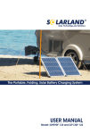
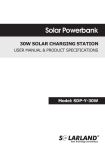
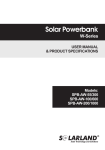
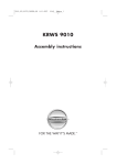
Solar LED Matrix Lamp Kit
User Manual
&
Product Specifications
Head Office
12Fl., C Bldg., 16 Changjiang Rd.,
Wuxi,214028,Jiangsu,P.R.China
Tel: +86-510-81191956
Fax: +86-510-85203812
www.solarland.com
[email protected]
Chicago Office:
PO BOX 6128, Lindenhurst,
IL 60046, USA
Tel : 847-282-4796
Fax: 847-245-8649
E-mail: [email protected]
Model
BSS-00504S
Index
General safety.................................................Page1
System Components........................................Page1
How Solar Home System Works..........................Page1
Specifications..................................................Page2
Installation.....................................................P age2
Electrical Connection........................................Page4
Maintenance...................................................P age6
Trouble-shooting Guide....................................Page6
FAQ...............................................................P age7
Warranty........................................................P age7
General Disclaimer...........................................Page7
Value Parameters
12V
Max. Charging Current/Load Current
≤1A
≤2mA
Current Natural Loss
5W
STC Power
System components
Components
Your system should include all the following components. If there is anything missing
please contact the distributor you purchased the kit from to arrange replacement.
Solar Module
Battery
17V
Operating Current (Imp)
0.29A
Open-Circuit Voltage (Voc)
21.6V
Short-Circuit Current (Isc)
0.34A
Battery Type
Maintenance Free Lead-acid battery
12V/5.0AH
Capacity
12 Super Bright LED
Light Source
0.6W
Rate Power
LED Lamp(4pcs)
PV Module
Power Pack
Extension Cable
Spare Part
(2sets)
Manual
DC Lamp
Phone Charging Kit
Charging Time
Cigarette Lighter
Adopter(1pc)
How Solar Home System Works
Operating Voltage (Vmp)
3pcs
4pcs
4pcs
1set
(7 kinds)
1pc
PV Module:
Absorbs sunlight and converts it to electricity.
Controller:
1 Protection against over-charge
2 Protection against over-discharge
3 Protection against short circuit and overload
Luminosity
50lm
Approximately 17 hours in full sunlight when the battery is fully
discharged.
1 Lamp
72 hours
2 Lamps
36 hours
3 Lamps
24 hours
4 Lamps
18 hours
-20~50°C(-4~122°F)
Solar Panel Installation Guidelines
Switch
PV Module
50mA
Installation
12V DC output
for lamp
Battery
12V
Rate Current
Operating Temperature Range
How Solar Home System Works
Controller
Continuous
Use
Rate Voltage
5V DC output
for mobile
phone
Environmental Parameters
The PV module should be installed in areas where the following environmental
conditions exist:
Temperature Range: -20°C to 40°C*
Operating temperature: -20°C to 80°C
High temperature will reduce the performance of module, lowering power output.
Good ventilation can effectively reduce the effect of power loss due to excessive heat.
Panels should be installed in a well ventilated location.
The solar panels are water resistant but not waterproof. Do not submerge in water or
expose the panel to a continual flow of water.
Orientation & Tilt
The solar panels perform best when set up at 90° to the direct sunlight.
Power Pack
Page1
Specifications
Please read this manual carefully before using your solar power system.
Save this manual. This manual contains guidelines for maintaining your power system.
Please follow the installation instructions on pages 2-5 of this manual to ensure
personal safety and satisfactory product operation.
Normal Voltage
Page2
Installation
General safety
Specifications
General safety
Controller Installation
Lamp Installation
Hang the lamp based on requirements.
Installation
100mm
Back View
Mounting Hole
The Power Pack and
the lamps are
designed for indoor
(protected) use only.
Note: Please place the solar panel at a position directly facing the sun.
Electrical Connection
Please avoid shadowing
cells in order to prevent
solar module reduction
in power.
STEP1
Press the button on the top of the PowerPack to the "ON" position before use.
Main Switch
Do not install module on smooth roof.
Use a blunt object to depress the switch.
Turn switch off for long term storage.
Do not drill holes in
frame.
Do not install the
module or mounting
system in high
corrosion areas.
Do not drop or
allow objects to
fall onto module.
STEP2
Before use, fully charge the battery.
Charging
Keep away from fire.
Flammable
Gases
The module must not be
immersed in water (either
fresh or salt) or constantly
be exposed to water (either
fresh or salt) (i.e. from
fountains, sea spray).
Do not install module
near flammable
gases.
DC socket for 12VDC PV module
Charging Indicater
(Yellow LED)
PV Module
Do not mark the
back of modules
with sharp materials.
AC Power Supply
Do not stand or step on the glass
surface of a solar module. The
glass may break. The module
may also stop generating power.
Yellow LED Mode:
Do not destroy modules,
tear down modules.
Page3
· ON----Battery is charging.
· Flash----Battery is fully charged.
Warning:
The Power Pack can be supplied with the AC charger with special
configuration. Please do not use other AC adaptor not supplied by
use. This may influence the electrical properties of the products.
Page4
Electrical Connection
Installation
Knock two nails into the wall
which the PowerPack is going
to be installed, with the distance
of 100mm between the two nails.
Hang the Power Pack on the wall.
STEP3
Working
A
B
D
C
E
Do not change any system components with non approved Solarland components.
Failure to follow this instruction could cause system failure and nullify the product
warranty.
PV Module; …clean the glass surface of the module as necessary. Use water and a soft
sponge or cloth for cleaning. A mild, non-abrasive cleaning agent can be used if
necessary. Do not use dishwasher detergent.
Protect the cables against mechanical stress when they are being laid (e.g. against
pressure from being trodden on).
If a mechanical defect is identified in a PV panel (e.g. if the glass in the front panel is
broken by a forceful impact), this panel must be changed and replaced with a new
one.
Cleaning the battery terminals, do not use any metal files or other harsh abrasives
(eg. sand paper) to remove corrosion or oxidization from terminals or posts as this
may cause a poor fit when terminals are reconnected.
Non-use:turn off the main switch during long-term storage.
Maintenance
Maintenance
Trouble-shooting Guide
The Solar Powapack kit is a maintenance free design and there are no userserviceable parts. If you have any problems please follow the trouble-shooting
guide below or call the distributor you purchased the kit from.
Replace battery
C DE
New Battery
DC sockets for
12VDC LED lamp
DC socket for 5VDC
mobile phone
Switch for A, B, C
Switch for D, E
Low Voltage Indicater
(Red LED)
Mobile Phone
(not included)
Note:
Ensure correct connection as indicated.
The red LED is a low voltage indicator.
When this lights up the kit will stop
working till recharged.
The battery/controller
should be installed in a
shaded location, avoiding
direct sunlight and must
be free from moisture.
The surface temperature of
the controller will heat up
during use, please avoid
contact and exposure with
combustibles.
If the battery/controller is
to be used outside, please
place the unit in a protective
housing keeping it free from
dust and water.
Safety Warning!
Page5
is “+”
is “-”
Note: Please don’t
reverse “+”and “-”.
Charging indicater(Yellow LED) not on and not flash:
Check if solar panel DC plug and cable OK or not.
Check if main switch off or not.
Battery capacity is low, the battery should be changed.
Low voltage indicater(Red LED)on , lamp not working:
The battery is low voltage, the system should be charged.
When on overcurrent or short-current happens, please turn off main switch. When faults
removed, please turn on the main switch again.
Low voltage indicater(Red LED) on, battery running out in a short time:
Battery capacity is low, the battery should be changed.
Charging indicater(Yellow LED) flash, battery fully charging in a short time:
Battery capacity is low, the battery should be changed.
Page6
Trouble-shooting Guide
Electrical Connection
AB
FAQ
What direction should I tilt the module?
The solar panel's top surface is the area that generates electricity and thus it is
this surface should be exposed to the sun to capture maximum light.
The maximum light is captured when the panel surface is at 90° angle to the sun's
rays.
Will shading affect my solar module output?
FAQ
Yes. Don't install the PV module where shading occurs. Shading could cause loss of
output.
Will my solar module work in cloudy weather?
Yes, solar modules can work in low light conditions. On overcast or cloudy days
there will be less energy reaching the solar module and therefore less output.
Will my solar module output increase with temperature rising?
No. High temperature will reduce the performance of the panel, lowering the power
output. Good ventilation can effectively prevent overheating photovoltaic
components.
How often should I clean my solar module?
There is no need to clean if the modules have pitch (at least 15º).Rainwater has the
ability to clean them. Excessive debris and dust should be removed using warm
water.
Should I cover my solar module in the winter months?
No, solar modules can withstand extreme environments including heat, cold, ice
and even hail and work normal.
Warranty
Warranty
Limited Warranty Materials & Workmanship
The seller warrants the solar power system to be free from defects in material and
workmanship under normal application, installation, usage and service conditions.
If the solar modules fail to conform to this warranty, then for a period ending 12 months
from date of sale to the original end-customer, the Seller at its option, either repair or
replacement or refund, or refund the purchase price as paid by the Customer
[“Purchase Price”]
Limited Warranty Power Output
The seller guarantees that the output power of PV module is more than 80% of the
minimum Peak Power within 5 years. If the output power of PV module can't reach the
warranty data, SOLARLAND will , at its own discretion, replace such loss in power either
by replacing the defective PV modules or by refunding the Purchase Price Provided that
the loss in power is due to defects in materials and /or workmanship under normal
installation, application and use.
General Disclaimer
In no event shall the manufacturer liable for any damage or personal injury caused by
non-compliance to the operating instructions and safety suggestions in this brochure.
The manufacturer will not bare any responsibility for misuse, damage, injure, incorrect
installation and system design as such.
Page7