1
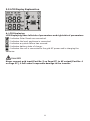
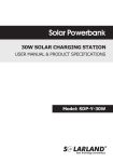
W-Series
USER MANUAL
& PRODUCT SPECIFICATIONS
Models:
SPB-AW-55/300
SPB-AW-100/600
SPB-AW-200/1000
Thank you for choosing the Solarland® Solar Powerbank. Please read this manual
carefully before setting up and using the product. Pay close attention to all
instructions and keep this user manual for future reference.
Content
1. Product Introduction
01
1.1 Features
01
1.2 Technical Data
01
1.3 Storage and Working Environment
02
1.4 Application
02
2. Installation Instructions
03
2.1 Kit Components (All sold Separately)
03
2.2 Solar Panel Installation
03
2.3 Powerbank Installation
05
2.4 Connecting the System
05
3. Powerbank Control Panel & Connections
06
3.1 Schematic Drawings & Powerbank Layout Explanation
06
3.2 Connecting an External Battery to the AC bank
08
3.3 Performance
09
3.4 Setting Up the Powerbank
10
3.5 LCD Display Explanation
11
3.6 Common Faults & Fixes
12
4. FAQ & Trouble Shooting Guide
15
5. Warranty
17
1. Product Introduction
Since 2003 Solarland has been developing, designing and manufacturing off-grid solar
systems, bringing power to structures and villages all over the world where no electrical
power grid exists. The Solar Powerbank is the latest innovation in this series of power
products: Simplified structure, reliable performance, easy operation. It can offer stable
and reliable electricity to those regions that are short of power or even without power.
1.1 Features
Compact, portable and convenient
Quick and easy installation
Simple design; …adapt the system to meet your requirements
LCD display clearly shows system status at all times
Reliable, maintenance free performance
Power generation and storage for uninterrupted use in places without electricity
Various applications ranging from everyday to emergency power supply
1.2 Technical data
Component
Solar Panel
Parameters
SAP-W/300
SAP-W/600
SAP-W/1000
Type NO./Qty
SLP100-12(1pc)
SLP100-12(1-2pcs)
SLP100-12(2-4pcs)
Peak Power (Pm)
100W
100W
100W
Open Circuit Voltage (Voc)
21.6V
21.6V
21.6V
Max. Power Voltage (Vmp)
17.2V
17.2V
17.2V
Short Circuit Current (Isc)
6.46A
6.46A
6.46A
Max. Power Current (Imp)
5.81A
5.81A
5.81A
2×1.5 mm² x 5m
2×1.5mm² x 5m
2×1.5mm² x 5m
Nominal Capacity
55Ah
100Ah
200Ah
Nominal Voltage
12V
12V
12V
275x175x235mm
440x235x280mm
530x285x285mm
SPB-AW-55/300
SPB-AW-100/600
SPB-AW-200/1000
Cable
Battery
Max. Outer Dimensions
(LxWxH)
Model
Type NO.
Rate Voltage
12V
Max. PV Charging Current
Powerbank
10A
DC
Controller High-Voltage
30A
30A
≤25V
Max. PV Input Voltage
14±0.2V
13.7±0.2V
Low-Voltage Disconnection
10.5±0.2V
10.7±0.2V
Low-Voltage Reconnection
11.5+0.2V
12.6±0.2V
Disconnection
01
Parameters
Component
AC
Charger
DC
Output
Charging Starting Voltage
N/A
11.5±0.2V
Charging Stopping Voltage
N/A
13.7±0.2V
USB Max. Output
Voltage/Current
5V/600mA
DC Outlet Max. Output
Current/Voltage
1A/One Route/12V
≤300W
Modified Wave
Output Voltage/Frequency
≤600W
≤1000W
Pure Sine Wave
AC 120V±10% 60Hz±2Hz
≤1.5%
Self-comsunption
Low-Voltage Disconnection
10.0±0.5V
High Voltage Disconnection
Other
SAP-W/1000
8A
Output Wave Mode
Inverter
SAP-W/600
N/A
Max. AC Output Power
Powerbank
SAP-W/300
Max. AC Charging Current
10.0±0.5V
15.5±0.5V
Low-Voltage Alarm
10.5±0.3V
Dimension(LxWxH)
300x180x550mm
10.5±0.3V
460x240x550mm
560x290x480mm
1.3 Storage and Working environment
A. Storage
Place in a well ventilated area free from dust and debris;
Ideal Temperature Range for Safe Storage:
Inverter & Battery: -10°C ~ 40°C;
Solar panel: -40°C~ 90°C;
Avoid humid conditions and moisture, such as condensation;
Keep away from erosive gases and/or liquids;
When storing for long periods it is important to completely charge and
discharge the system at least once every 6 months.
B. Working environment
Ideal Working Temperature Range:
Inverter & Battery: -10°C ~ 40°C;
Solar panel: -40°C~ 90°C;
Moisture: 0 ~ 90%;
Elevation: ≤5000m;
Avoid humid conditions and moisture, such as condensation.
1.4 Application
The Solarland Powerbank kits are scaled to meet many different power demands and
can be used in many applications including households, schools, communications,
marine, military, rural electricity, agriculture, street lamps, street stalls, special events,
etc.
02
2. Installation Instructions
2.1 Kit Components (All sold Separately)
Component
SAP-W/300
SAP-W/600
SAP-W/1000
Type
Qty.
Type
Qty.
Type
Qty.
SPB-AW-55/300
1pc
SPB-AW-100/600
1pc
SPB-AW-200/1000
1pc
55Ah
1pc
100Ah
1pc
200Ah
1pc
Solar Panel
SLP100-12
1pc
SLP100-12
1-2pcs
SLP100-12
2-4pcs
Solar Bracket(*Optional)
SLB-0103
1set
SLB-0103
1-2sets
SLB-0103
2-4sets
Powerbank Cabinet
Battery(*Recommend)
User’s Manual
Other
2.2 Solar Panel Installation
A. Orientation & Tilt
The solar panels perform best when set up at 90° to the direct sunlight.
90°
NOTICE
Panels should be installed in a well ventilated location. High temperatures will
reduce the performance of module, lowering power output.
The solar panels are water resistant but not waterproof. DO NOT submerge in
water or expose the panel to a continual flow of water.
03
Do not install the panel in a location
where the sunlight may be blocked
from getting to the panel.
Do not install panels flush to the roof,
there must be a gap for ventilation.
Do not drill holes in
frame.
Do not install the
module or mounting
system in high
corrosion areas.
Do not drop or
allow objects to
fall onto module.
Keep away from fire.
Flammable
Gases
The module must not be
immersed in water (either
fresh or salt) or constantly
be exposed to water (either
fresh or salt) (i.e. from
fountains, sea spray).
Do not install module
near flammable
gases.
Do not mark the
back of modules
with sharp materials.
Do not destroy modules,
tear down modules.
B. Optional Solar Panel Mounts
Wall mount
Roof mount
Note: Panel mounts are not included in the kit and are optional add-ons. The kit
shown above is the Solarland SLB-0103 Tilt Mount Kit.
04
2.3 Powerbank Installation
It is most important you follow these instructions properly otherwise damage
and/or injury can occur.
NOTICE
Place and operate the unit on a stable and level floor.
Do not spray or splash water directly onto the unit.
Keep the unit away from direct sunlight.
Keep away from open flame and high temperatures (Keep well ventilated).
Avoid placing near corrosive gases and/or liquids.
Place in a well ventilated, cooler location.
Do not insert objects and/or liquids into the unit.
It is advised that only a qualified professional open the box and perform
maintenance.
2.4 Connecting the System
DANGER
In order to avoid electrocution and fire hazards, pay attention to the following:
Before commencing installation, make sure the switch on the Powerbank is OFF.
It is advised that only a qualified professional install the system.
Avoid contact with terminals and circuit boards.
Be careful not to short-circuit the terminals.
The AC inverter has a high-voltage output, avoid contact at all times.
This kit has been specifically designed to work with just the provided
components. The use of non-standard components, such as different panels
can cause damage and void the warranty.
THE METAL HOUSING OF THE POWERBANK SHOULD BE PROPERLY
GROUNDED AT ALL TIMES. PLEASE CONSULT WITH A QUALIFIED
ELECTRICIAN FOR GROUNDING ADVICE.
WARNING:
FAILURE TO GROUND, OR IMPROPER GROUNDING, MAY RESULT IN
SERIOUS INJURY AND/OR POSSIBLE DEATH.
05
NOTICE
Ensure all master power switch and breaker switch are in the off position before
commencing with the connections.
Connection Order:
1. Powerbank to Battery
2. Powerbank to Solar Panel/s
Please DO NOT do withstanding voltage test to the Powerbank. Irrepairable
damages to the Powerbank and components will occur.
3. Powerbank Control Panel & Connections
3.1 Schematic Drawings & Powerbank Layout Explanation
A. SAP-W/300
No.
5 1
13 14
6
11
7
12
8
9
4
3 2
10
Name
Function
1
Analog Voltmeter
Display the voltage of the battery
2
DC 12V output(L1,L2,L3,L4)
Connect with 12V DC load
3
USB 5V output
Connect with 5V DC load
4
120V AC output
Connect with 120V AC load
5
Switch
Inverter switch
6
Green LED
Inverter work indicator
7
Red LED
Inverter failure indicator
8
Red LED
Charging indicator
9
Green LED
DC load indicator
10
Breaker
General power switch
11
Solar panel +
Connect with PV +
12
Solar panel -
Connect with PV -
13
Battery +
Connect with the battery +
14
Battery -
Connect with the battery -
Note: Allowing for additional battery storage in parallel with battery
inside cabinet.
06
B. SAP-W/600
No.
1
2
9
7 8 5
4
10 11
6 3
12
13
Name
Function
1
LCD display
Display the status of system
2
DC 12V output(L1,L2,L3,L4)
Connect with 12V DC load
3
USB 5V output
Connect with 5V DC load
4
120V AC output
Connect with 120V AC load
5
Grid input
Connect with grid Power
6
Switch
Inverter switch
7
Green LED
Inverter work indicator
8
Red LED
Inverter failure indicator
9
Breaker
General power switch
10
Solar panel +
Connect with PV +
11
Solar panel -
Connect with PV -
12
Battery +
Connect with the battery +
13
Battery -
Connect with the battery -
Note: Allowing for additional battery storage in parallel with battery
inside cabinet.
C. SAP-W/1000
No.
1
2
9
7 8 5
10 11
4
6 3
12
13
Name
Function
1
LCD display
Display the status of system
2
DC 12V Output(L1,L2,L3,L4)
Connect with 12V DC load
3
USB 5V output
Connect with 5V DC load
4
120V AC output
Connect with 120V AC load
5
Grid input
Connect with grid Power
6
Switch
Inverter switch
7
Green LED
Inverter work indicator
8
Red LED
Inverter failure indicator
9
Breaker
General power switch
10
Solar panel +
Connect with PV +
11
Solar panel -
Connect with PV -
12
Battery +
Connect with the battery +
13
Battery -
Connect with the battery -
Note: Allowing for additional battery storage in parallel with battery
inside cabinet.
Note:
The SAP-W/600 and SAP-W/1000 units feature both solar charging and AC grid charging capabilities.
When the solar and AC inputs are connected they will both charge the battery when the battery voltage
is below 11.5V. This combined charge will continue till the batteries are fully charged at 13.7V. If the
battery voltage is above 11.5V only the solar panels will be charging the system except in initial use.
07
3.2 Connecting an External Battery to the AC bank
Additional battery storage capacity can be added to the Powerbank utilizing the
parallel connections provided.
Built-in Battery
External Battery
+
SOLAR PANEL
-
+
BATTERY
-
BREAKER
-
+
+
-
BATTERY
BATTERY
Please note the charging performance of the system will be affected when adding
additional battery capacity. It will take the system longer to fully charge the
batteries.
The type and nominal voltage of the external battery has to be same as the
battery inside the powerbank, but battery capacity can be different.
When adding a battery please follow the steps below:
Turn off the BREAKER
Securely connect the positive and negative battery terminals to the
corresponding terminals on the Powerbank. (Incorrect connection can cause
system damage.)
Make sure all connections are secure and tight. (Loose connections will cause
system performance issues and possible system damage.)
The wires/cables to the external battery should not exceed 1m (40”) It is
important to select the correct wire size to ensure the best possible system
performance; …see chart below:
CABLE
SAP-W/300
6mm²
SAP-W/600
12mm²
SAP-W/1000
20mm²
Turn on the BREAKER and the system should function properly with the
additional battery capacity.
08
3.3 Performance
Battery Charging Function:
The Solarland Powerbanks utilize a "state of the art" Smart controller to ensure
the most efficient battery charging. The battery will not overcharge and the
system has reverse polarity protection.
Low Voltage Disconnection Function (LVD):
The Solarland Powerbanks utilize a long life inverter that automatically
recognizes a battery with low voltage and will disconnect the DC loads to avoid
permanent battery damage. This disconnect occurs at 10.7±0.2V on models
SPB-AW-100/600 and SPB-AW-200/1000. The disconnect occurs at 10.5±0.2V
on model SPB-AW-55/300. All models will disconnect the AC loads when
10.0±0.5V.
High Voltage Disconnection Function (HVD):
The rated input voltage of the inverter is 12V. If the input voltage of inverter is
more than 16V, the High Voltage Disconnection will occur automatically to
protect the battery.
Electronic Overload Protection:
When the total power draw exceeds the rated power of the inverter, the
overload protection will stop the inverter functioning within 10 seconds. The
protection indicator light will indicate the system overload state.
Power down the system by turning the power breaker switch to the OFF
position and disconnect the loads. After 10~15 seconds switch the Powerbank
back ON and start connecting the loads being careful not to overload the unit.
Short Circuit Protection:
When a short circuit occurs the inverter stops functioning immediately. The
protection indicator light will indicate the short circuit has occured. You must
identify the source of the short circuit and resolve the issue.
Power down the system by turning the power breaker switch to the OFF
position. After 10~15 seconds switch the Powerbank back ON.
High Temperature Protection:
When the inverter temperature reaches 75C it stops functioning immediately.
The protection indicator light and alarm will indicate the temperature is a
problem. Power down the system by turning the power breaker switch to the
OFF position. Allow the system to cool down and we recommend you look for a
better ventilated location to place the unit to avoid future overheating. After
sufficient cooling switch the Powerbank back ON.
09
3.4 Setting Up the Powerbank
Please carefully read the following safety precautions and related
operation instructions before commencing installation and set-up. :
Ensure the intended location meets the requirements set out in section 2.3 of
this document.
Ensure the power breaker switch is set to the OFF position.
Ensure the battery to be used meets the minimum battery voltage
requirements.
Connect the red cable to the positive battery terminal and the black cable to the
negative battery terminal. Make sure all connections are tight and secure.
Note that connecting the battery incorrectly can cause a short circuit and
system damage.
Switch the power breaker switch to the ON position. The LCD display will
indicate the battery charge condition.
Switch the inverter on and the indicator light should come on.
Connect the solar panels to the assigned positive and negative connections on
the Powerbank. If the panels are in sunlight the LCD will indicate the state of
the solar charging.
DANGER
It is VERY IMPORTANT to follow the set-up instructions exactly.
The breaker switch will automatically disconnect the system in the event
of a major failure.
Do NOT disconnect the breaker switch when the system is working
normally.
If you have to disconnect using the breaker switch be sure to disconnect
the solar panels first.
When re-setting the breaker switch make sure you reconnect the solar
panels after the breaker switch has been reconnected.
10
3.5 LCD Display Explanation
A. LCD Displaying
LCD Displaying have left side of parameters and right side of parameters
: Indicates Solar Panels are connected.
: Indicates the load, appliance is connected.
: Indicates a system failure has occured.
: Indicates battery state of charge.
: Indicates the unit is connected to the grid AC power and is charging the
batteries.
DANGER
Never connect grid input(Part No. 5 on Page 07) to AC output(Part No. 4
on Page 07), it will cause irreparable damage to the inverter.
11
B. Adjusting System Parameters
: Interface Button; ...use this to switch between the various charging
parameters. (Figure 1)
: Use this button the adjust the parameter up.
: Use this button the adjust the parameter down.
To reset to factory default press and hold the + button for more than 5 seconds.
HVD
Main interface
Load mode
LVD
LVR
(Low Voltage Reconnection)
Figure 1
C. LCD Screen Explanations
View & set system parameters
Display on left shows solar panels are connected, load is
connected, battery status, battery voltage, and AC output voltage.
0000This function switches the load On/Off.
View and set the High Voltage Disconnect
The value for the HVD - High Voltage Disconnect is shown. When
this is achieved the controller will disconnect the charge to prevent
over-charging battery.
This parameter can be adjusted up or down. Press
and the
number will flash. Use the
to adjust the parameter up or
down, then press the
for 5 seconds till the number stops
flashing.
Press
again to go to the next parameter.
12
View and set the Low Voltage Reconnect
The value for the LVR - Low Voltage Reconnect is shown.
This parameter can be adjusted up or down. Press
and the
number will flash. Use the
to adjust the parameter up or
down, then press the
for 5 seconds till the number stops
flashing.
Press
again to go to the next parameter.
View and set the Low Voltage Disconnect
The value for the LVD - Low Voltage Disconnect is shown. When
this is achieved the controller will disconnect the load to prevent
over discharging battery.
This parameter can be adjusted up or down. Press
and the
number will flash. Use the
to adjust the parameter up or
down, then press the
for 5 seconds till the number stops
flashing.
Press
again to go to the next parameter.
View and set the Load Working Mode
24h - Indicates Normal Mode: The bank has continual DC power
output.
1h-23h-means Light Control and Time Control Mode, the bank has
DC power output after dark, and then cut off the DC power output
according to the timer setting.
0h-Means Light Control Mode, the bank has DC power output after
dark, and then cut off the DC power output after dawn.
In this interface you can use the button
,
to adjust the
parameter. The number will be flash. After long press the key
(>5seconds), the number will be saved and stop flash. Short press
to give up save the number and exit to next interface.
13
3.6 Common Faults & Fixes
Error Code E04 - Low Voltage Protection:
The LVD protection has been activated. and the load circuit has
been disconnected by the controller. The batteries require to be
charged and the system will resume normal operation when the
LVR voltage has been attained.
Error Code E02 - Overload Protection:
The screen will display as shown. The system load has exceeded
the controller has entered the system parameter. Turn the unit off,
remove loads. Add loads carefully to not overload the system
again and press the
button to restore power to the load.
Error Code E01 - Short Circuit Protection:
The screen will display as shown. This indicates a short circuit on
the load loop circuit. Check the load/s for damage after trouble
shooting and clearing the problem, press the
button to restart
the system.
14
4. FAQ & Trouble Shooting Guide
Problem
LCD Display Not Working
LCD Displays, but no
DC Output. No fault
displayed on LCD
No AC Output
Solar Panels connected,
but no Charging Status
showing on the LCD
5VDC & 12VDC Outputs
only work at night
Possible Reason
Corrective Action
Circuit Breaker Switch in OFF
position.
Set Circuit Breaker to the ON
position.
Battery is connected in reverse.
Turn Powerbank OFF, disconnect and
reconnect the battery correctly.
(Note the reverse connection of the
battery may have damaged the
inverter.)
Battery is deteriorated and voltage
is below 9V.
Check battery condition and try
recharge. If they do not hold the
charge they should be replaced with
new batteries.
The LCD wire conncetions are loose
or have come away from the meter
during transportation.
Turn the Powerbank off and
reconnect the wires to the LCD
meter.
The solar controller wire
conncetions are loose or have come
away from the meter during
transportation.
Turn the Powerbank off and
reconnect the wires to the solar
controller.
DC Output is not turned ON.
Press the button below the LCD
screen to turn the DC Output ON.
Poor connections on the solar
controller, particularly check the
load output connection.
Turn Powerbank OFF and reconnect
all solar controller connections.
Inverter switch is not in the ON
position.
Press Switch to the ON position.
Inverter Switch is damaged.
Turn Powerbank OFF and replace
Switch.
Inverter is damaged.
Turn Powerbank OFF and replace
Inverter.
Poor connections on the solar
controller, particularly check the
load output connection.
Turn Powerbank OFF and reconnect
all solar controller connections.
Solar panels are not correctly
positioned.
Ensure the panels are placed in full
sunlight with no shadows or other
obstructions.
Insufficient sunlight.
In cloudy and rainy condistions the
solar panels will generate a small
charging current. The Powerbank
will not detect the current if it is
below 0.1A.
Solar Panel connections are loose.
Check all connections and tighten
where required.
Solar Panels connected in reverse.
Turn Powerbank OFF and reconnect
the Solar Panels correctly.
Load mode of the controller has
been reset to 0~23.
Reset the load mode to 24.
15
Problem
Possible Reason
Corrective Action
LCD Displays E01 Fault
Short circuit has occurred.
Turn Powerbank OFF & check all
components and cabling to clear
any short circuit.
LCD Displays E02 Fault
DC Output overload has occurred.
Turn Powerbank OFF & remove all
loads. Turn the Powerbank ON and
reconnect the loads, careful not to
overload again.
LCD Displays E04 Fault
Battery Voltage is LOW.
Turn Powerbank OFF & remove all
loads. Turn the Powerbank ON and
allow the battery to recharge before
connecting any loads.
AC Output Overload has occurred.
Turn Powerbank OFF & remove all
loads. Turn the Powerbank ON and
reconnect the loads, careful not to
overload again. Check the power
draw of the appliances does not
exceed the system limit.
AC Appliances peak power exceeds
system limitations.
Check each appliance power
specification and ensure they do not
exceed the inverter output.
Battery input voltage is too high.
Check battery voltage and ensure it
does not exceed the maximum
safety voltage of the inverter.
AC Starting Load is too big.
This is a normal situation and occurs
when too many loads are attached
at start up. Disconnect the loads
and add them in order from largest
to smallest.
Low Voltage.
Battery is discharged and has low
voltage. Turn Powerbank OFF and
recharge the batteries till a full
charge is achieved.
High Temperature, the Powerbank
has overheated.
Turn Powerbank OFF. Remove loads
and allow to cool. Check location of
the Powerbank is well ventilated.
RED LED is ON, no AC
output
AC Load Power is low
Alarm is sounding
Battery discharges
quickly
AC load is too big, resulting in rapid
discharge.
Lifetime of battery is over.
16
Reduce the AC Load.
Add external battery to handle the
extra power requirements.
To change a new battery.
5. Warranty
The Solarland AC Powerbank has a warranty of 1 year from date of invoice.
Please read these instructions very carefully. The manufacturer shall not be
liable for damages to the system, including the battery, caused by misuse
and/or the user failing to follow the instructions as set out in this manual.
The manufacturer shall not be liable for damages caused by service or repair by
an unauthorized person, incorrect set-up & Installation or bad system design.
The warranty is immediately void if batch numbers, serial numbers or
identification-marks are manipulated or are unidentifiable.
The warranty covers parts and components only.
The warranty does neither cover the cost of transportation for the return of the
system or components, nor for the additional shipment of replacement
components.
The warranty does not cover the cost for installation or reinstallation of the
system.
17
Head Office
12Fl., C Bldg., 16 Changjiang Rd.,
Wuxi,214028,Jiangsu,P.R.China
Tel: +86-510-81191956
Fax: +86-510-85203812
www.solarland.com
[email protected]
Version: M1305U
General Disclaimer
In no event shall the manufacturer liable for may damage or personal injury caused by
non-compliance to the operating instructions and safety suggestions in this brochure.
The manufacturer will not bear any responsibility for misuse, damage, injury, incorrect installation
and/or system design as such.