1
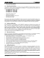
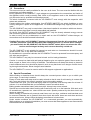
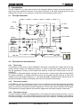
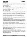
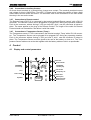
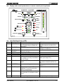
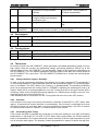
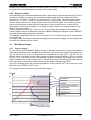
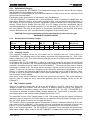
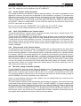
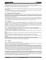
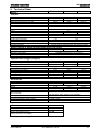
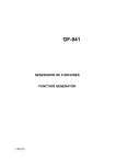
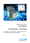
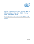
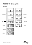
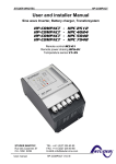
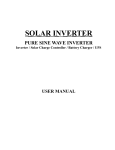
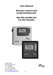
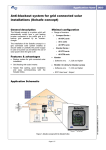
STUDER INNOTEC
XP-COMPACT
User and installer Manual
Combi Inverter, Battery charger
and Transfersystem
XP-COMPACT XPC 1112
XP-COMPACT XPC 1624
XP-COMPACT XPC 1648
Remote control RCC-01
Temperature sensor CT-35
Solar charge controller XPCxxxx-S
AC cable cover CFC-01
IP-23 top cover C-IP23
STUDER INNOTEC
Rue des Casernes 57
CH-1950 SION
User manual
TEL: ++41 (0)27 205 60 80
FAX: ++41 (0)27 205 60 88
EMAIL : [email protected]
XP-COMPACT V2.0 E
STUDER INNOTEC
XP-COMPACT
Summary
1
General Information .................................................................................................................3
1.1
1.2
1.3
1.4
1.5
1.6
2
OPERATING INSTRUCTIONS ................................................................................................................................3
QUALITY AND WARRANTY.................................................................................................................................3
WARRANTY DISCLAIMER ...................................................................................................................................3
LIABILITY DISCLAIMER ......................................................................................................................................3
PRECAUTIONS ....................................................................................................................................................4
SPECIAL PRECAUTIONS ......................................................................................................................................4
Introduction...............................................................................................................................5
2.1
PRINCIPLE SCHEMATIC .......................................................................................................................................5
2.2
DESCRIPTION OF MAIN FUNCTIONS .....................................................................................................................5
2.2.1 The inverter...................................................................................................................................................5
2.2.2 The transfer system .......................................................................................................................................5
2.2.3 The battery charger.......................................................................................................................................5
2.2.4 The solar charge controller (optional)..........................................................................................................6
2.2.5 Remote control ..............................................................................................................................................6
2.3
BATTERY CONNECTIONS ....................................................................................................................................6
2.3.1 Connection in parallel ..................................................................................................................................6
2.3.2 Connection in serie .......................................................................................................................................6
2.3.3 Connection in parallel and in serie...............................................................................................................7
3
Mounting and installing ...........................................................................................................7
3.1
INSTALLATION PLACE.........................................................................................................................................7
3.2
FIXING................................................................................................................................................................7
3.2.1 XP-COMPACT..............................................................................................................................................7
3.3
PROTECTION COVER IP23...................................................................................................................................7
3.4
CONNECTIONS ....................................................................................................................................................7
3.4.1 General instructions on connecting ..............................................................................................................7
3.4.2 Protection cover for the terminals connections ............................................................................................8
3.5
CONNECTING PANEL / FRONT SIDE .....................................................................................................................8
3.6
CABLING/WIRING ...............................................................................................................................................9
3.6.1 Pre-installation settings ................................................................................................................................9
3.6.2 Connection to battery....................................................................................................................................9
3.6.3 Connecting the 230Vac-Consumer Appliance (AC OUTPUT) .....................................................................9
3.6.4 Connecting the 230Vac Input (AC INPUT)...................................................................................................9
3.6.5 Connecting the Solar modules: SOLAR +/- (Only with solar option)...........................................................9
3.6.6 Connection to Auxiliary Contact.................................................................................................................10
3.6.7 Connection to Temperature Sensor (Temp.) ...............................................................................................10
4
Control.....................................................................................................................................10
4.1
DISPLAY AND CONTROL PARAMETERS..............................................................................................................10
4.2
DISPLAY AND CONTROL PARAMETERS ON REMOTE CONTROL PANEL (OPTIONAL) ............................................11
4.3
LIGHT EMITTING DIODES (LED) ......................................................................................................................11
4.4
PUSH BUTTONS .................................................................................................................................................12
4.5
TURNING KNOBS ..............................................................................................................................................12
4.6
THE INVERTER .................................................................................................................................................12
4.6.1 Charge detection system „Standby“ ...........................................................................................................12
4.6.2 Overload .....................................................................................................................................................12
4.6.3 Overheating (Over Temp) ...........................................................................................................................12
4.6.4 Battery Condition........................................................................................................................................13
4.7
THE BATTERY CHARGER ..................................................................................................................................13
4.7.1 Cycle of charge ...........................................................................................................................................13
4.7.2 Equalization charging.................................................................................................................................14
4.7.3 Default value for battery charger ...............................................................................................................14
4.7.4 Charging current ........................................................................................................................................14
4.8
THE TRANSFER SYSTEM ...................................................................................................................................14
4.8.1 Set the transfer voltage threshold ...............................................................................................................15
4.8.2 FAST (UPS)- MODE for the Transfer Switch .............................................................................................15
User manual
XP-COMPACT V2.0 E
1
STUDER INNOTEC
XP-COMPACT
4.8.3 Delayed mode of the Transfer System .........................................................................................................15
4.9
THE SOLAR CHARGE CONTROLLER (OPTION)....................................................................................................15
4.10
THE MULTIFUNCTIONAL CONTACT ..................................................................................................................16
4.11
THE TEMPERATURE SENSOR .............................................................................................................................16
5
The Remote Control ...............................................................................................................16
5.1
REMOTE CONTROL PLUG-IN ..............................................................................................................................16
5.2
POWER MONITOR..............................................................................................................................................16
5.3
BATTERY CONDITION:......................................................................................................................................17
5.4
FAULT INDICATOR ............................................................................................................................................17
5.4.1 Overtemp. (10) ............................................................................................................................................17
5.4.2 Overload (11)..............................................................................................................................................17
5.4.3 Battery low/high..........................................................................................................................................17
5.5
DEPORTED ALARM CONTACT AND ON/OFF CONTROL ........................................................................................17
5.6
MANUAL CONTROL OF THE AUXILIARY CONTACT ............................................................................................17
6
Programming: .........................................................................................................................17
6.1
STANDARD SETTING .........................................................................................................................................18
6.1.1 Battery voltage ............................................................................................................................................18
6.1.2 Auxiliary contact.........................................................................................................................................18
6.2
RESET VALUE ...................................................................................................................................................18
6.3
BATTERY VOLTAGES AND ABSORPTION TIME: ..................................................................................................18
6.3.1 Table of voltage and timing threshold.........................................................................................................18
6.3.2 Set the voltage and timing threshold ...........................................................................................................18
6.4
PROGRAM THE AUXILIARY CONTACT ...............................................................................................................19
6.4.1 Principle......................................................................................................................................................19
6.4.2 The programming of the Auxiliary Contact is carried out in the following Steps.......................................19
6.4.3 Example ......................................................................................................................................................19
6.5
DISABLING SOME OF THE XP-COMPACT FUNCTIONS .....................................................................................20
6.5.1 Diagram of the different mode ....................................................................................................................20
7
Maintenance............................................................................................................................20
8
EC Compliance .......................................................................................................................20
9
Technical Data ........................................................................................................................21
User manual
XP-COMPACT V2.0 E
2
STUDER INNOTEC
XP-COMPACT
1 General Information
1.1
Operating instructions
This manual is a part of the delivery package of every XP-COMPACT inverter-charger. It serves as
guidelines for safe and efficient operation of XP-COMPACT. The instructions are only valid for use
with the following appliances and options:
- XP-COMPACT XPC1112
- XP-COMPACT XPC1624
- XP-COMPACT XPC1648
-
Temperature sensor CT-35
Remote control RCC-01
Solar charge controller. XPCxxxx-S
AC cable cover CFC-01
IP-23 top cover C-IP23
Every person who installs a XP-COMPACT and/or works with it must be fully familiar with the contents of this manual and must follow exactly all the warnings and safety instructions. Installation of
or any work on the XP-COMPACT must be carried out by a qualified and trained staff. Installation
and application must comply with the respective local installations codes and safety regulations.
1.2
Quality and Warranty
During production and assembling, all XP-COMPACT appliances go through many controls and
tests. Production, controls and tests are carried out in accordance with firm and established procedures. Every XP-COMPACT has its own serial number, which helps to refer back to its original
data in the event of controls or repairs. That is why you should never remove the identification
plate showing the serial number. The production assembly and tests on all XP-COMPACT appliances are totally carried out in our company in Sion, Switzerland. The warranty for these appliances is valid for uses and operating possibilities mentioned in this manual.
The warranty period for the XP-COMPACT is 2 Years.
1.3
Warranty Disclaimer
We do not accept any responsibility for any damages occurring through use, manipulation, working
situation and handling, which are not explicitly mentioned in these operating instructions.
Following cases are not covered by the warranty:
•
High voltage at INPUT (i.e. 48V at the Battery INPUT of XP-COMPACT 1112)
•
Reverse polarity on Battery connections (+/- reversed)
•
Running liquid or oxidation through condensation in the appliance
•
Defects caused by force, physical or mechanical means
•
Changes not explicitly authorized by STUDER INNOTEC
•
Not or only partly tightened screws and nuts after change of fuses or connecting cables
•
Connecting other sources of energy such as PV-Modules on the INPUT „SOLAR +/-„
•
Transport damage, i.e. through bad handling and /or packing
•
Damage from atmospheric overvoltage
1.4
Liability Disclaimer
Respecting this manual, servicing and method of installation, functioning, application and maintenance of the appliance can not be controlled or supervised by STUDER INNOTEC. Hence we do
not accept any liability and responsibility for damages, loses and costs which result through the
use of this appliance or which result through incorrect installation, incorrect operation or wrong
application and maintenance or which by some other means maybe connected together to these.
Similarly, we do not accept any responsibility for any violation of the patents rights or violation of
any third party’s rights resulting from the use of this appliance
STUDER INNOTEC reserves the right to modify the technical data or these operating instructions
without issuing any prior notice.
User manual
XP-COMPACT V2.0 E
3
STUDER INNOTEC
1.5
XP-COMPACT
Precautions
This manual must be readily available for the user at all times. The user must be familiar with the
precautions and safety aspects.
During operation of XP-COMPACT, high voltages are generated at the connections and inside of
the appliance which could be deadly fatal. Work on the appliance and on the installation should
only be carried out by qualified and trained personnel.
The whole installation connected with the XP-COMPACT must comply with the respective valid
codes and ordinances.
Persons without the written authorization from STUDER INNOTEC are strictly forbidden to carry
out any changes or repairs on the appliances. For authorized changes only original parts are to be
used.
The XP-COMPACT may only be used when it has been installed in accordance with these instructions and all parts have been correctly assembled and installed.
On the IN- and OUTPUT points of the XP-COMPACT only the already selected energy sources
and consumer appliances should be connected.
In order to carry out any maintenance or repair work on the XP-COMPACT without danger, all
connections must be disconnected beforehand.
Caution: Even when a XP-COMPACT has been disconnected from the all connections, at the
OUTPUT point there could still be deadly fatal voltages present. To remove these voltages
you must switch the XP-COMPACT ON with the ON/OFF switch. After one minute the electronics are discharged and any work can now be safely carried out.
The XP-COMPACT is only suitable for internal use and under no circumstances should it be subjected to snow, rain, or any other wet conditions
By installations in motorized vehicles the XP-COMPACT must be protected from water-spray and
any other wet conditions..
The XP-COMPACT may only be connected to lead –acid or lead-gel batteries.
Caution: In normal use lead-acid and lead-gel batteries give out explosive gases. Never smoke or
allow a spark or flame in the vicinity of batteries. The batteries must always be stored or placed in
a well ventilated area, they should be placed in such a way that there is no danger of short circuiting through carelessness. Never charge frozen batteries.
The XP-COMPACT is not to be used or sold for life support equipment or applications.
1.6
Special Precautions
While working on batteries there should always be a second person close to you or within your
voice range, in case help is needed.
Plenty of fresh water and soap must be ready at hand so that in case of acid coming in contact with
skin, eyes and clothes, the areas in question can be thoroughly washed.
If acid enters the eyes, you must thoroughly wash the eyes with cold running water for at least 15
minutes. It is recommended that you immediately consult a medical doctor.
Baking powder neutralizes battery acid electrolyte. Always keep some at hand.
Special care must be taken when working with metal tools near or on the batteries. With tools such
as screwdrivers, spanners etc. short-circuits can result. Sparks produced by the short-circuit can
cause an explosion.
When working on batteries all personal metal items such as rings, necklaces and bracelets must
be removed. Batteries are so powerful that short-circuit with these items can melt them and thus
cause severe burns. Always follow the battery manufacturer’s instructions.
Under certain conditions the XP-COMPACT or a connected generator can start automatically.
While working on an electrical installation you must ensure that these appliances are disconnected
beforehand from the installation.
User manual
XP-COMPACT V2.0 E
4
STUDER INNOTEC
XP-COMPACT
2 Introduction
The XP-COMPACT is a sine wave inverter with integrated battery charger and solar charge controller with many additional functions, it has been developed to be used as stand-alone (no grid
feeding) AC provider, or as continuous / break-free current supply provider (UPS).
2.1
Principle schematic
AC IN
Input
100nF
PE
230Vac
10nF
1uF
L
PE Output
N
10nF
Filter
4x2,7MΩ
CT35
Temp. Sensor
1uF
Microprocessor,
Control, Adjustment
SOLAR
Display
Solarmodule
Max. 6m
230Vac
Inverter
Charger
150A
1uF
N
AUX. CONT.
Battery
BATTERY
AC OUT
L
Remote
Remotecontrol
control
Temp.
6p
RJ11
8p
Remote control
COMPACT
RCC-01
Max. 40m
AC IN
CHARGER
SOLAR CHARGE
EQUALIZE
Program
INVERTER - CHARGER
TRANSFER
AC OUT
RESET
ALARM
(Select)
Over Temp.
Overload
Battery
Low/High
Contact active
Contact manual
AUXILIARY
2.2
CONTACT
(Program)
A
%
160
130
INVERTER
70
100
60
80
50
60
40
40
30
20
20
10
10
Ch
arg
er
5
Inv
ert
er
OFF
ON/ OFF
(Change
status)
Description of main functions
2.2.1 The inverter
The sinewave inverter built in the XP-COMPACT generates a sinusoidal AC voltage with an exceptionally precise voltage and stabilized frequency. In order to start large electric motors, the user
has the possibility to employ a short-start-power which is 3-times the nominal power of the XPCOMPACT.
The inverter is protected against overload and short-circuits. A power stage with the latest MOSFET power transistors, a toroidal transformer and a fast regulating system make-up a robust and
reliable inverter with highest efficiency. A 1-20 Watt adjustable charge detection system serves to
provide the smallest energy consumption and ensures a long life for the battery.
2.2.2 The transfer system
XP-COMPACT can be connected to an AC source, for example a stand-by emergency generator
or the AC network. With the transfer system, on one side you have an alternating voltage at the
output for use by the connected consumer appliances. On the other side the batteries are charged.
The distribution of energy between the consumer appliances and battery charger is automatic.
2.2.3 The battery charger
The built-in battery charger is so designed that it can charge the battery quickly and fully. A microprocessor controlled, 3 to 4 Step charging process ensures the optimum charging of the batteries.
The desired charging current can be set continuously from 0 to maximum, according with particular
User manual
XP-COMPACT V2.0 E
5
STUDER INNOTEC
XP-COMPACT
technical specification (chap.6). The battery charger is meant for the lead-acid and lead-gel batteries. Thanks to the floating charge system the battery can remain continuously connected.
2.2.4 The solar charge controller (optional)
With the built-in solar charge controller, the XP-COMPACT is a complete solar-power-center. In a
solar installation this controller ensures that the batteries are charged correctly. With the XPCOMPACT, batteries can be charged with a generator and with the solar modules at the same
time. The charging of batteries with both energy sources is carried out fully automatically.
2.2.5 Remote control
As an option, a remote control can be connected to XP-COMPACT. Extra display and programming possibilities are available on the remote control (see Chap.5). The remote control is supplied
with a 20m long cable. This cable can go to 40m long. On the remote control output power and
charging current are also monitored.
2.3
Battery connections
Lead-acid batteries are normally available in blocks of 2V, 6V or 12V. In most cases, to generate
the necessary operating voltage and the capacity of the batteries for the XP-COMPACT many batteries have to be connected together in parallel and or in series. Following three examples are
shown:
2.3.1
Connection in parallel
12V
2.3.2
12V
12V
12V
Connection in serie
2V
2V
2V
2V
2V
2V
2V
2V
2V
2V
2V
2V
12V
24V
2V
2V
12V
User manual
2V
12V
2V
2V
12V
2V
12V
XP-COMPACT V2.0 E
48V
6
STUDER INNOTEC
2.3.3
XP-COMPACT
Connection in parallel and in serie
12V
12V
12V
12V
24V
3 Mounting and installing
3.1
Installation place
The location of the XP-COMPACT must be chosen by the following criteria:
- Protection against unauthorized handling
- Dry dust free room, no condensation
- Never install directly over the battery and never in a cabinet together with the batteries
- Keep ventilation holes free. The ventilation of XP-COMPACT is designed in such a way that it can
only work efficiently when the appliance is fully lying on its back
In mobile installations it is important to keep down the vibrations as low as possible.
3.2
Fixing
3.2.1 XP-COMPACT
Basically the XP-COMPACT can be installed in any desired location. Preferred is that the appliance be wall mounted with battery cables downwards. The XP-COMPACT is fixed on the wall with
four screws through the four holes (diam. 5.5mm) which are accessible from the outside. In motor
vehicles XP-COMPACT must be fixed on vibrations reducing elements. The XP-COMPACT must
not be fixed on a combustible base, as the back of the casing can get hot and reach up to 80 degree Celsius.
3.3
Protection cover IP23
This cover IP23 (Order ref. C-IP23), can be easily installed after the fixation of the XP-COMPACT. To install it,
release a little the too screws down and more the two up.
Then insert the IP 23 cover between the XP-COMPACT
and the wall. The cover must touch the screws. Lock on
the four screws, it’s ready.
3.4
Connections
3.4.1 General instructions on connecting
The cable connection on the terminals AC INPUT / AC OUTPUT / 15A 230VAC are carried out
with a screwdriver Nr.1 and the connection on the SOLAR terminal with a screwdriver Nr.2.
The conductor cross section on the terminals AC INPUT / AC OUTPUT / 15A 230VAC of the connecting cable must be minimum 2.5mm2.
All connecting cables and also the mounted battery cables must be fixed with strain relief clamps.
The XP-COMPACT is delivered with battery cables already connected.
The battery cables must never be extended. If the extension can not be avoided, then the conductor cross section must be elevated accordingly.
To protect the battery cable, a fuse corresponding to the conductor cross section must be fixed
directly on to the battery.
All cables must be tightly screwed in place. For safety, a yearly control is recommended. In mobile
installations control must be carried out more often.
User manual
XP-COMPACT V2.0 E
7
STUDER INNOTEC
XP-COMPACT
Connecting must be done by qualified staff. Material such as cable, connectors and distribution
boxes, fuses etc. used in the installation must comply with the respective valid low-voltage installation rules and regulations.
3.4.2
Protection cover for the terminals connections
The protection cover is available in option (Order
ref. CFC-01) and avoids to do wrong hazardous
contact on the terminals 230Vac. It is mounted with
strain relief clamps for the cable.
3.5
Connecting panel / Front side
J
M Caution: Check battery
polarity (+/-) before connecting!
A wrong connection could
damage the system.
Don't open before
disconnect line and battery
BATTERY
.
SOLAR
A
Remote
control
Equalize
Transfer delay
L
16A-250Vac
AC IN
Temp.
sens.
N
B
C
A
B
C
D
E
F
G
H
Battery +/SOLAR +/Remote contr.
Equalize
Transfer delay
Temp.
Aux. Contact
AC Input
J
K
N
ID Plate
AC Output
16A Protection
User manual
D
E
F
G
AC OUT
L
N
N
H
L
K
Battery cable (already installed)
Connecting terminal for Solar modules
Connecting terminal for Remote Control RCC-01
Slide switch for equalization of the Battery
Slide switch for Transfer Delay
Connecting terminal for Temperature sensor CT-35
Connecting terminal for Auxiliary Contact
Connecting terminal for AC-input. Located directly above this
terminal is the automatic safety cut-out for this terminal.
Identification plate with Technical data and Serial number
Connecting terminal for AC-output
16A Protection switch for the Transfer system
XP-COMPACT V2.0 E
8
STUDER INNOTEC
3.6
XP-COMPACT
Cabling/wiring
Connecting of the XP-COMPACT is a very important step in the installation. You must take care
that all connecting work is carried out in a clean and correct manner and that under no circumstance a cable is connected to a wrong terminal.
Connecting of the XP-COMPACT must be carried out in the following order. In case of dismantling
this order must be reversed.
3.6.1 Pre-installation settings
Before you start with the cabling of the XP-COMPACT you must set the type of battery. In case
that sealed-gel batteries are used then you must set the small slide-switch „Equalize“ which is on
the front with the connecting terminals, to OFF position. In case of „normal“ lead-acid batteries,
these can handle a higher equalizing charge, the same slide switch can be set to ON position. In
case of doubt leave the setting in OFF position.
3.6.2 Connection to battery
Get the batteries ready for connection: matching battery terminals, matching fuse on a clamp. Prepare battery cables, if necessary press on cable tabs/shoes. Connect red cable on Plus(+)- Pole
and the black cable on the Minus(-) pole. On connecting the second cable to the battery pole a
spark is produced, because for a short time high current flows into the XP-COMPACT to charge
the capacitors. For this reason follow strictly the safety measures described in this manual. Check
if the red LED OFF (13) is lit. If not, press shortly on the switch ON/OFF (19), now OFF should be
lit.
On connecting the battery the XP-COMPACT needs 1 – 2 Minutes to calculate the actual capacity
of the battery. During this time the battery condition is shown as 100% charged. (LED 15 lit).
If the LED 12 Battery Low/High is lit, the battery charge is too low. If the LED 12 Battery Low/High
is blinking, the battery charge is too high.
Caution: With a wrong battery voltage the XP-COMPACT can be destroyed. (For example:
connecting a XPC 1112 to a 48V-Battery).
Nevertheless if the XP-COMPACT had been connected with reverse polarity, it is highly probable
that the fuse inside the casing is broken. Before opening the casing cover all terminals must be
disconnected including the battery. If the XP-COMPACT does not function after the change of the
fuse and correction of the polarity, it means that it is broken and must be sent for repair.
3.6.3 Connecting the 230Vac-Consumer Appliance (AC OUTPUT)
The 230V consumer appliance must be connected to the screw terminal AC OUTPUT. For this,
use a 3-core cable with a conductor cross section of 2,5mm2. Connections are marked as follows:
“N“ Neutral, “PE“ Earth, “L“ Live.
Caution: High voltage can by there. By sure that’s the XP-COMPACT is turned off (LED 13 alight)
before the connecting.
3.6.4 Connecting the 230Vac Input (AC INPUT)
The 230V-supply from network or from a generator must be connected to the screw terminals AC
INPUT. For this use a 3-core cable with a conductor cross section of 2,5mm2. Connections are
marked as follows: “N“ Neutral, “PE“ Earth, “L“ Live.
3.6.5 Connecting the Solar modules: SOLAR +/- (Only with solar option)
Solar modules are connected on these terminals. Under no circumstance should any other energy
source i.e. wind generator be connected to these terminals! Only solar modules must be connected
with two cables +/-. Depending on the power of the modules, the cable cross section should be 2.5
up to 6mm2. Before connecting it is necessary to check with a Voltmeter that the voltage of the
Module meets the following values:
XPC 1112 17-25V/30A, XPC 1624 34 – 45V/30A, XPC 1648 68 – 90V/20A.
User manual
XP-COMPACT V2.0 E
9
STUDER INNOTEC
XP-COMPACT
3.6.6 Connection to Auxiliary Contact
On these three terminals is a potential free change-over contact. The maximal permitted current
and voltage for this is 16A/250Vac. The LED 5 “Contact active” shows the position of them: alight
means active and off means non-active. The schematic view of the connections on the front shows
the relay in the non-active mode.
3.5.7 Connection to Remote control
The Remote Control RCC 01 is connected in the terminal marked „Remote control“ with a RJ11/8
connector. The Remote Control can be plugged IN or plugged OUT during any operation situation.
Push in the connector, without forcing it, until you hear the „click“, now the connector is locked in
place. The same applies to the plug in the Remote Control. The length of the cable for Remote
Control should not exceed 40m. We deliver it with 20m cable.
3.6.7 Connection to Temperature Sensor (Temp.)
The Temperature sensor CT-35 is connected in the terminal marked „Temp“ with a RJ11/6 connector. The Temperature Sensor can be plugged IN or plugged OUT during any operating situation.
Push in the connector without forcing it, until you hear a „click“, now the connector is locked in
place. The Temperature Sensor must be glued to the wall of the battery or close to it. The Temperature Sensor cable must not be tied together with the battery cables or laid in a rope/bundle.
4 Control
4.1
Display and control parameters
7
23
AC IN
1
8
CHARGER
Current adj.
22
24
0%
Reset
Solar charge
100%
19
0
ON /
OFF
20W
13
3
15
Equalize
User manual
14
BATTERY
12
XP-COMPACT V2.0 E
AC OUT
Search mode
INVERTER
Standby adj.
Off / Alarm
Temporary off
Batt 100%
Absorption
Batt undervolt.
Batt overvolt.
10
STUDER INNOTEC
Display and control parameters on remote control panel (optional)
COMPACT
INVERTER - CHARGER
TRANSFER
8
AC IN
AC OUT
2
7
9
CHARGER
SOLAR CHARGE
INVERTER
14
4 Program
15
5 Contact active
16
6 Contact manual
17
RCC-01
90
160
80
130
70
100
60
80
50
60
40
40
Over Temp.
30
20
11
Overload
20
10
12
Battery
Low/High
10
5
13
OFF
25
ON/OFF
(Change status)
19
Light Emitting Diodes (LED)
LED
1
Marking
AC IN
2*
CHARGER
3
SOLAR
CHARGE
Program
Contact active
Contact manual
4*
5*
6*
7
21
%
160
10
18
AUXILIARY CONTACT
(Program)
4.3
20
3
EQUALIZE
RESET
ALARM
(Select)
A
100
Inverter
1
Charger
4.2
XP-COMPACT
LED lit
Voltage at the AC IN input is within
the accepted range (voltage and
frequency)
Battery Charger is working
Connected Solar modules are
delivering energy
Program mode for Aux. Contact
Auxiliary Contact is activated
Aux. Cont. manually activated
Transfer system is active. Input
AC voltage is directly connected to
AC OUT outlet
Voltage is present at the AC OUT
outlet
8
AC OUT
9*
INVERTER
Inverter is working
10*
Over Temp.
For the time being the XPCOMPACT is out of service because of overheating.
11*
Overload
The XP-COMPACT is out of service because of overload or shortcircuit
12
Batt. Low/High
Battery voltage is too low
User manual
XP-COMPACT V2.0 E
LED blinks
Voltage, outside of the selfadjusted values is at the AC IN
input.
The input voltage is out value
(voltage or frequency)
Transfer system (by-pass) is disabled (see chap.6.5.1)
The Inverter is in Standby mode.
No loads are detected at the output
Inverter mode is disabled (see
chap.6.5.1)
Battery voltage is too high
11
STUDER INNOTEC
13
OFF
XP-COMPACT
XP-COMPACT is turned off. Turn- XP-COMPACT is for the time being turned off. Turning it back on
ing it back on is only possible
will follow automatically!
manually.
14
Battery Charger and/or Solar
Charge Controller are doing an
equalization cycle
15-18*
Charge condition of Battery
25*
CURRENT
MONITOR
LED 15 – Absorption time is running
Display the value of the output power in % of Pnom (in Inverter Mode)
and the charge current in Amps. (in Charger Mode)
4.4
Push buttons
19
ON/OFF
Turning the XP-COMPACT on and off (Help Button for Programming)
20*
RESET
Alarm Signal off (Help Button for Programming)
21*
Aux. Contact
Control Aux. contact (Help Button for Programming)
4.5
Turning Knobs
22
CHARGER
Adjustment for max. Charging Current (Not for Solar charge controller)
23
TRANSFER
Adjustment for Transfer Voltage Threshold (TRANSFER – INVERTER)
24
STANDBY
Adjustment for „Standby“ system
* Only on the remote control RCC-01
4.6
The Inverter
An Inverter is built in the XP-COMPACT, which generates a sinusoidal alternating voltage of a very
high quality. With this Inverter any alternating voltage consuming appliance 230Vac up to the
nominal power of your XP-COMPACT can be operated. Thanks to the generous dimensioning of
the XP-COMPACT, you can operate appliances requiring higher power than the nominal power of
the XP-COMPACT for a short time. The XP-COMPACT provides up to 3-times the nominal power
to start motors.
4.6.1 Charge detection system „Standby“
In order to avoid unnecessary discharge of the battery, the inverter switches OFF automatically if
no consuming appliance is connected and switches ON automatically again if a consuming appliance is connected. The LED 8 blinks if the inverter is in Standby-Mode. The switching-on/starting
level can be adjusted with the turning knob 24 „STANDBY. Adjusting the switching-on level is as
follows: Switch off all consuming appliances; turn the Turning Knob 24 to the right until the LED 8
is blinking, switch on the smallest consuming appliance (i.e. Mobile phone charger); turn the Turning Knob slowly to the left until LED 8 is lit.
If the Standby mode is not wanted, turn the Turning Knob 24 to the left, to the OFF position.
4.6.2 Overload
If the Inverter is too long or too heavily overloaded, it switches off and LED 13 „OFF“ blinks. After
approx. 10 seconds the inverter switches on automatically. If the Inverter is overloaded four times
one after the other in a short time, then it no longer switches on automatically. The LED 13 remains
lit. Press the push button 19 „ON/OFF“ in order to switch on the inverter.
4.6.3 Overheating (Over Temp)
If the Inverter has been overloaded for a long time or it has been working in a too high surrounding
temperatures, it will switch off. The LED 13 „OFF“ blinks. After cooling down, the inverter switches
back on automatically. One minute before the inverter switches off for too high temperature it gives
out an acoustic alarm signal. The Auxiliary Contact programmed in factory to detect the high tem-
User manual
XP-COMPACT V2.0 E
12
STUDER INNOTEC
XP-COMPACT
perature synchronizes the relay with the alarm signal. In this way, for example, an emergency back
up system can be started without any break in the energy supply.
4.6.4 Battery Condition
Deep discharging of the lead-acid batteries leads to high losses in capacity and early aging. This is
why battery condition is continuously controlled and supervised. With low voltage the inverter
switches off. The LED 12 „L/H Batt.“ is lit and the LED 13 „OFF“ blinks. When the battery voltage
gets up to 12.1V / 24.2V / 48.4V, the Inverter switches on automatically. One minute before the
Inverter switch off due to low voltage it gives out an acoustic alarm signal. If the Auxiliary Contact
has been programmed to detect the low voltage then it synchronizes the aux. contact with the
alarm signal. In this way, for example, an emergency back up system can be started without any
break in the energy supply.
The low voltage is set to 11.8V / 23.6V / 47.2V. These settings are standard for most batteries.
These voltage levels are maintained by the built-in Battery-Management-System of XP-COMPACT
by matching the load and the battery condition.
This setting is comparable with the levels of 10.8V/ 21.6V / 43.2, which are given for most batteries
on nominal load.
All voltage levels (equalization absorption floating and disconnection voltage), can be programmed
by mean of the optional remote control.
4.7
The Battery charger
4.7.1 Cycle of charge
The full automatic XP-COMPACT Battery Charger is adjusted at the factory so that most lead-acid
and lead-gel batteries can be charged to the maximum. As soon as the minimum alternating voltage for the AC IN set on the Turning Knob 23 is available at the input (LED 1 AC IN is lit), the
transfer switch is activated and the battery charger is switched on automatically (LED 2 on optional
RCC-01 is lit). The battery is fully automatically charged matching to the charge level, the presettled voltage levels and the charge current. Thanks to the built-in Float Charge System, the batteries can be left connected for unlimited time with the Battery Charger switched on.
During the charging phase the consuming appliances at the outlet AC OUT are continuously supplied with power (LED 8 AC OUT is lit).
The charger functions are shown in the following diagram:
[V/cell]
[A]
2.50
Equalization
70
2.3
Absorption
60
Floating
Charging current (adjusted)
2.1
40
1.9
20
A
User manual
A
Charging time
B
Egalization time
C
Absorption time
D
Floating
t
B
C
D
XP-COMPACT V2.0 E
13
STUDER INNOTEC
XP-COMPACT
4.7.2 Equalization charging
Before you program the XP-COMPACT for Equalization-charge you must check with your supplier
that the batteries are suitable for this process.
Equalization is recommended for the lead-acid batteries in order to mix well the electrolyte fluid
and to clean the lead plates.
Equalization mode should never be used when using Gel-Batteries
If the XP-COMPACT is operating with a lead-acid battery, which is suitable for equalization, the
slide switch „Equalize“ which is on the cable connection side, must be placed in the ON position. In
this setting, at every 25 charge cycles an equalization cycles is carried out for 30 minutes (factory
setting). During such a charge cycle the LED 14 is lit. Charge cycle with equalization can be
started independently of the actual program. For this the slide switch must be slid from “OFF” to
the “ON” position. The LED 14 will light up. If the periodic equalization is not required, slide switch
must be slid back to the „OFF“ position after the completion of the manual cycle.
CAUTION: During the equalization process, the batteries produce lot more gas.
DANGER OF AN EXPLOSION!!
4.7.3 Default value for battery charger
Low voltage
Float Charge
Absorption
Equalization
Absorpt. Time
LED 13
LED 12
LED 11
LED 10
LED 10->13
12V 24V 48V 12V 24V 48V 12V 24V 48V 12V 24V 48V
12/24/48V
11.6 23.2 46.4 13.5 27.0 54.0 14.4 28.8 57.6 15.6 31.2 62.4
2h
These values could be modified thanks the optional remote control.
4.7.4 Charging current
The maximum charging current for the battery can be adjusted with the Turning Knob 22
(CHARGER). The charging current of the battery should be set to approximately 10 – 20% of the
battery capacity (at C10). This means that the charging current for a battery with 200Ah should be
set between 20 – 45A.
In charging mode, the XP-COMPACT is acting as a consumer (load) like any other connected load
to the grid or the generator. His consumption should be added to the consumption of every active
consumer connected at the AC output of the XP-COMPACT. The maximum used current used by
the charger is limited to 6A. This mean that the minimum required current from the source is 6A or
greater. If that’s not the fact, the charging current should be diminished proportionally. For instance, a *A source will required to adjust (knob 22) the charging current to half of the max. value.
In order to insure a perfect functionality of the overall system with a generator as AC source, this
one should be at least 1500VA
Note: IN no cases the XP-COMPACT will limit the current from the source. The source should be
sized in order to supply all active connected appliance plus the charging current of the XPCOMPACT.
4.8
The Transfer system
When an ac voltage is at the input AC IN of the XP-COMPACT, the LED 1 AC IN is lit. When this
voltage is higher than 200Vac, and the frequency is between 44Hz and 65Hz, this voltage is
switched directly to the battery charger and to the output AC OUT. The LED 7 TRANSFER is lit.
The inverter is switched off and the battery charger switched on. This process is automatic, unless
the charger mode or the transfer mode is disabled (see Chap. 8.5.1)
The maximum current of the Transfer switch is 15A. That means through this system, consuming
appliances up to a maximum of al 3500 Watt can be operated. When the Battery Charger is working, part of this power is used for the charging the battery.
The Transfer system is protected against overload with a 16Amp. Automatic safety fuse on the AC
Input side of the XP-COMPACT. If the system has been overloaded the button/pin of the fuse will
pop-out. To put the automatic safety system back in to operating you must push this pin back.
Note: In the Inverter operation, The XP-COMPACT generates a true sinusoidal and quartz stabilized output voltage. When, however the XP-COMPACT is supplied from a grid or a generator and
User manual
XP-COMPACT V2.0 E
14
STUDER INNOTEC
XP-COMPACT
the transfer contact is active, then you have at the output AC OUT the same voltage as that at the
input. This voltage can not be modified by the XP-COMPACT!
4.8.1 Set the transfer voltage threshold
The voltage threshold of the transfer is factory settled at 200Vac. This value is acceptable in most
application. However, this value can be adjusted fro 150 to 230Vac if necessary. To proceed to the
adjustment of this level, insert a screw-driver N° 0 vertically in the hole (23) and turn gently clockwise or counter clockwise to increase or diminish the threshold level.. When the Input voltages
reach the settled value on turning knob, the inverter switch off and the AC INPUT go directly on the
AC OUTPUT. When the voltage INPUT is less of 20V the value set, the transfer is stop and the
OUTPUT switch back on the inverter.
Don’t use the turning knobs “TRANSFERT” (23) to adjust the AC OUTPUT voltage!
This is only it’s only a voltage threshold level to enable or disable the transfer.
4.8.2 FAST (UPS)- MODE for the Transfer Switch
The quick and break free Transfer mode is programmed with a slide switch „Transfer Delay“ OFF,
which is on the front side (cable connections side).
The aim of the XP-COMPACT is to supply the consuming appliance with a break-free alternating
voltage. When the incoming voltage AC IN no longer matches values which have been set with the
Turning Knob 23, the Inverter switches on at once. The transfer is carried out in 0.02 seconds. This
quick transfer ensures a break-free function for most consuming appliances. If you have an alternating voltage back at the input AC IN, transfer system starts up again without any break, and the
inverter is stopped.
4.8.3 Delayed mode of the Transfer System
The delayed mode of the transfer system „Transfer Delay ON“ is programmed with the slide switch
on front with the cable connections. The XP-COMPACT provides a break-free alternating voltage
for the consuming appliance. A quick transfer switch is not always sensible nor is it always desired.
For example, when the consuming appliances are operated by a small back-up generator, an overload of a short duration on such a generator, i.e. start of a vacuum cleaner etc., has the effect of
decreasing the voltage for a short time. As in such cases the transfer to the Inverter is not desirable, the transfer system can be programmed with a delay. When the slide switch (Transfer delay)
is in the „On“ position, the transfer to the inverter takes place with a delay of 5 seconds. If the voltage falls below 100Vac, the transfer takes place without delay! The transfer switching to the Inverter takes place without any break.
4.9
The Solar charge controller (option)
The XP-COMPACT also has a Solar Charge Controller built in. For charging the batteries, Solar
modules can be connected to the screw terminal SOLAR +/-. The in-built controller is a „Shunt controller“ for the maximum input current of 30A for XPC 1112 and XPC 1624 and 20A for XPC 1648.
The operating voltage of Solar panels to be connected must match the actual operating voltage of
the XP-COMPACT and never exceeds the max. rated value.
Under no circumstances should any other systems such as wind-generator be connected at the
input of the Solar Charge Controller.
The Solar Charge Controller works automatically and is always in operation. As soon as the energy
is delivered from the Solar Charge Controller, LED 3 “SOLAR CHARGE” is lit and the batteries are
being charged. The Solar Charge Controller works even when the Battery Charger is functioning.
The way of working is the principally the same as that of the Battery Charger. The function is described in the section on Battery Charger. The programming and the adjustments, thanks the optional remote control, are carried out in accordance with the same conditions. Check with your battery supplier which adjustments must be carried out for your battery.
User manual
XP-COMPACT V2.0 E
15
STUDER INNOTEC
XP-COMPACT
4.10 The Multifunctional Contact
In the XP-COMPACT there is a built-in power relay. The potential-free change-over contact (NO –
NC) of this power relay is connected to the screw terminal AUX CONTACT.
Maximum Contact load:
230Vac /12Vdc/24Vdc/16Amp
60Vdc/3 Amp. !
The contact is activated when the XP-COMPACT is halted or by a fault condition, or by a normal
manual stop done by pushing push-button 19.
This auxiliary contact can be freely programmed for any displayed functional status through the
remote control (refer to chap.5)
4.11 The Temperature sensor
Operating voltage of lead-acid batteries change depending
on the temperature. To correct the operating voltages according to the actual temperatures, a temperature sensor can be
connected to the COMPACT.
The compensation through the sensor is –3mV/°C/Cell.
Order Number: CT-35
Dimensions: H x B x T / 58 x 51.5 x 22mm
5 The Remote Control
As an option a Remote Control can be connected to the XP-COMPACT through a standard supplied 20m long cable. It can be extended to 40m.
The Remote Control is suitable for surface mounting on the wall or on to a
switch board. It is fixed with 4 screws.
All operating controls and displays except from level adjustment are available
on the Remote Control. Several extra
features are implemented in the remote
control:
A charging current monitor (25)
Output power monitor (25)
The battery status monitor
Auxiliary contact programming
Battery voltage level adjustment
Remote Alarm contact and command
Remote control plug-in
5.2
8
AC IN
AC OUT
2
7
9
CHARGER
SOLAR CHARGE
Power monitor
INVERTER
14
15
5 Contact active
16
6 Contact manual
17
10
Over Temp.
11
21
A
%
100
160
90
160
80
130
70
100
60
80
50
60
40
40
30
20
Overload
20
10
12
Battery
Low/High
10
5
13
OFF
25
18
AUXILIARY CONTACT
(Program)
XP-COMPACT V2.0 E
RESET
ALARM
(Select)
20
3
4 Program
RCC-01
User manual
TRANSFER
1
EQUALIZE
The instantaneous power of the inverter
in % off Pnom or the charging current is
continuously displayed on LED lines
(25).
COMPACT
INVERTER - CHARGER
Inverter
The remote is delivered with a 20m long
cable and can be connected or disconnected at any time while the main unit is
running (hot plug).
The remote control can be mounted with
the frame or directly on a board. The
screws are not supplied.
Charger
5.1
ON/OFF
(Change status)
19
16
STUDER INNOTEC
5.3
XP-COMPACT
Battery Condition
Built-in microprocessor calculates the actual state of charge of the battery and displays it on LED
15 – 18. The LED 14 is lit when the system is carrying out a charge cycle with equalization.
The voltage levels and charge characteristics can be changed through Programming. The instruction for programming of battery levels is in the section „Programming”
5.4
Fault indicator
5.4.1 Overtemp. (10)
For the time being the XP-COMPACT is out of service because of overheating due to high ambient
temperature or excessive overload
5.4.2 Overload (11)
The LED indicator lights when the inverter is suffering a load higher than the permitted overload
during more than 5 seconds.
5.4.3 Battery low/high
The LED indicator lights when the battery voltage is too low and blinks when it is too high.
5.5
Remote alarm contact and on/off control
Remote contorl
In the Remote Control there is an additional Alarm Contact and a Control Input built in. These two
functions are available through Tipjack RJ11/4 for use. This Auxiliary
Contact is Front / Work Contact
(max. 0.5A!), which is independent of
the Auxiliary Contact of the XPCOMPACT. This contact is active in
case of an alarm of the XPON/OFF
COMPACT.
! -batt !
The Control Input is connected in
parallel to the ON/OFF- push button.
The XP-COMPACT can be switched
on or off through this input with an
impulse button or an impulse contact.
1234
COMPACT
Remote control
Dry contact
60V/0,5A
max.
only
Order Number for Remote Control: RCC-01
Dimensions: H x B x T / 111.5 x 136.5 x 25mm
Caution: No external voltage should be connected to this Input Control.
5.6
Manual control of the auxiliary contact
The auxiliary Contact can be operated at any time with the Push Button 21 (AUX. CONTACT). The
LED 6 „Contact manual“ lights up as information that the Contact is manually operated, and LED 5
„Contact active“ lights up when the Contact is active. By pushing the Push Button 21 a second
time, the Contact is deactivated. By pushing it the third time, automatic functions are restored.
When the auxiliary contact is manually controlled (LED 6 lit) the programmed control of the contact
is disabled. In program mode, the auxiliary contact may be automatically actuated by every displayed status of the XP-COMPACT. Refer to chapter 6.4 for programming the auxiliary contact.
6 Programming
Programming the charging parameter and the auxiliary contact is only possible thru the optional
remote control. This programming allows to change the factory setting parameters for battery management and auxiliary contact.
User manual
XP-COMPACT V2.0 E
17
STUDER INNOTEC
6.1
XP-COMPACT
Standard setting
The XP-COMPACT is delivered with the following default setting:
6.1.1 Battery voltage
Low voltage
Float Charge
End of Charge Voltage
Equalization
Absorption Time:
11.6V / 23.2V / 46.4V
13.5V / 27.0V / 54.0V
14.4V / 28.8V / 57.6V
15.3V / 30.6V / 61.2V
2 Hours
6.1.2 Auxiliary contact
Active in case of defect or manual turn off with the LED 10/11/12/13
6.2
Reset value
When the XP-COMPACT is to be connected to a battery or after an interruption (RESET), it is always programmed with these standard settings.
In order to get to these settings during operation you must press the three Push Buttons 20/21/22
simultaneously for a minimum of 2 seconds.
6.3
Battery voltages and absorption time
The voltage levels (low voltage, float charge, end of charge and equalization) and the duration of
the absorption charge can be changed.
The display of these voltages and the times in the program mode are in accordance with the diagram shown below:
6.3.1
Table of voltage and timing threshold
Low voltage
Float Charge
Absorption
LED 13
LED 12
LED 11
LED 12V 24V 48V 12V 24V 48V 12V 24V
14
12.0 24.0 48.0 13.7 27.4 54.8 15.0 30.0
15
11.8 23.6 47.2 13.6 27.2 54.4 14.8 29.6
16
11.6 23.2 46.4 13.5 27.0 54.0 14.6 29.2
17
11.4 22.8 45.6 13.4 26.8 53.6 14.4 28.8
18
11.2 22.4 44.8 13.3 26.6 53.2 14.2 28.4
The heavy printed values show the standard settings.
48V
60.0
59.2
58.4
57.6
56.8
Equalization
LED 10
12V 24V 48V
15.5 31.0 62.0
15.4 30.8 61.6
15.3 30.6 61.2
15.2 30.4 60.8
15.1 30.2 60.4
Absorpt. time
LED 10->13
4h
3h
2h
1h
0 – 1Min.
6.3.2 Set the voltage and timing threshold
The programming is done in accordance with the following steps:
Push and hold down, the Push Button 21 (Program) and the Push Button 19 (Change status) for
minimum 2 seconds simultaneously.
RESET
With the Push Button 20 (select) select with of the
ALARM
20
battery level and the absorption time to be changed.
(Select)
These four red
LED show the function set:
Low voltage
LED 13
Float charge
LED 12
Absorption (End of charge) LED11
Equalization
LED 10
Absorptions Time
LED 10/11/12/13
With the Push Button 19 (Change status) set the
desired parameter (voltage or the time) to modify
(LED 14/15/16/17/18). Push Button 19 (Change
status) to set the desired value according to the
User manual
14
15
16
17
10
Over Temp.
11
Overload
12
Battery
Low/High
13
OFF
18
21
XP-COMPACT V2.0 E
ON/OFF
(Change status)
19
18
STUDER INNOTEC
XP-COMPACT
table 6.3.1.
If desired, repeat the operation with any other parameter (voltage or time) to be changed.
If during 10 seconds no buttons are pressed, the selected values are automatically stored and the
XP-COMPACT switches back in to the normal operating status.
The voltage levels and times changed through programming are only first active with the next
charge cycle!
The voltage levels which are not suitable can greatly reduce the battery life or could even destroy
it! Therefore check beforehand with your battery supplier.
6.4
Program the auxiliary contact
With the Push Button 21 „AUXILARY CONTACT“ the contact can be manually switched on or off
independent of programming and the operating situation. The LED 5 “Contact active” show the
state of the contact. The drawing up the screw terminal “AUX CONTACT” is the inactive position
mode, LED 5 “Contact active” off.
The switching on and off of this contact can be freely programmed for every operating situation of
the XP-COMPACT witch situation is indicated with a LED. There is no limitation to its application
and it is left to your wishes and desires as to where and how you would like to use it.
6.4.1 Principle
The Auxiliary Contact can be basically programmed for any operating situation of the XPCOMPACT which is indicated with a LED. The programming is possible for one or more operating
situations. If the contact is programmed for many situations, it is activated as soon as the XPCOMPACT finds itself in any one of the programmed situations. This means that the way of workings of the contact meets that of the logic OR–Function.
6.4.2 The programming of the Auxiliary Contact is carried out in the following Steps
The Push Button 21 (Program) press down for min. 2 seconds. The LED 4 „Program“ is lit as an
indication, that the XP-COMPACT is in program mode.
A lit LED shows the programmed condition for the auxiliary contact. (LED 10/11/12/13 factory setting)
With the Push Button 20 (select), select the desired condition in which the contact should be activated.
With the Push Button 19 (Change status) confirm or change the status for this condition.
If desired, with the Push Button 20 (select) select another condition in which the contact should be
activated.
With the Push Button 19 (Change status) confirm or change the status for this condition.
If during 10 seconds no buttons are pushed, then the settled values are automatically stored and
the XP-COMPACT switches back to normal operating condition.
6.4.3
Example
6.4.3.1 Auxiliary Contact as generator starter
When in the programming of the Auxiliary Contact, the Battery Capacity (LED 15-18) is used as a
condition, then you must take note of the following requirements.
If you have to start an emergency back-up supply with a battery having a certain residual capacity,
then two battery levels must be programmed. The first (i.e. Battery 25% LED 17) for starting or
activating the Auxiliary Contact, and the second (i.e. Battery 100% LED15) for stopping or deactivating the Auxiliary Contact. By programming like this the Auxiliary Contact is active with the lowest
set condition and release when it has reached the highest programmed condition through charging.
6.4.3.2 Auxiliary Contact as Twilight Switch (With solar charger option)
The Auxiliary Contact of the XP-COMPACT can also be used as a twilight switch, i.e. for operating
automatically the exterior lighting. With it the connected solar modules measure the light intensity.
To function as a twilight-switch the Auxiliary Contact must be programmed so that the condition
SOLAR CHARGE (LED 3) is active. Programming must be carried out in steps and in accordance
with the description for the programming of the Auxiliary Contact.
User manual
XP-COMPACT V2.0 E
19
STUDER INNOTEC
XP-COMPACT
6.4.3.3 Second priority cut-off
The Auxiliary Contact can use to cut-off second priority load with the criteria of the battery status or
overtemp. One of the 4 LED 15 to 18 or 10 will be chosen as the cut off criteria. The second priority loads will be supply only if the battery as a sufficient residual capacity
6.5
Disabling some of the XP-COMPACT functions
Each different function charger, inverter and transfer can be disabled. This is useful for specific
applications witch required to disable some of these tree functions.
If you press the button (20) more than 2 seconds, you can have the access to the different possibilities shown in the following diagram.
In programming mode the display show only the different types of program with the three DEL 2,7
and 9 to each functions. To change the type of programming press shortly the button 20 until your
reach to the right function use according table below. After 10 seconds the XP-COMPACT exits the
programming mode and load the new change.
In user mode, the disabled functions are displayed by blinking LED. So you can see in witch mode
is disabled.
6.5.1
Diagram of the different mode
Show an off LED
Show a blinking LED
Show a lighted LED
9
AC IN
1
CHARGER
2
AC IN
1
CHARGER
2
AC IN
1
CHARGER
2
AC IN
1
CHARGER
2
7
7
7
7
8
AC OUT
9
INVERTER
8
AC OUT
9
INVERTER
8
AC OUT
9
INVERTER
8
AC OUT
9
INVERTER
All the functions are enabled. This is the factory setting.
The inverter is disabled. Only the transfer
switch and the charger will work normally.
Charger and transfer switch are disabled. the
inverter will work continuously even if there is
a correct AC voltage at the input
Inverter and charger are both disabled.
Only the transfer switch function is enabled in
input voltage and frequency is OK.
7 Maintenance
Apart from the periodic controls mentioned for the connections, the XP-COMPACT does not need
any maintenance. Keep the appliance clean and from time to time wipe it clean with a damp cloth.
8 EC Compliance
Hereby we state that the products described in this user manual meet the following standards:
EN50081 I/II, EN55014 – EN61000-2-3, IEC801 II/III/IV, LVD 73/23/EEC, EMC Dir. 89/336
CH-1950 Sion the 1st of January 2003
User manual
STUDER INNOTEC (R.Studer)
XP-COMPACT V2.0 E
20
STUDER INNOTEC
XP-COMPACT
9 Technical Data
Model
XPC1112
XPC1624
XPC1648
Inverter
Nominal battery voltage
Input voltage range
Nominal power
Maximum power load 30 min. P30
Maximum power load 5 sec
Maximum load
Maximum asymmetric load
Standby adjustment
Cos ϕ
Maximum efficiency
Consumption OFF/Standby/ON
Output voltage
Output frequency crystal controlled
Total harmonic distortion
Dynamic behaviour on load change 0 → 100 %
Overload and short circuit protection
Overheat protection
12 V
9.5 – 17 V
1100 W
1400 W
24 V
48 V
19 – 34 V
38 – 68 V
1600 W
1600 W
2200 W
2000 W
3 x Pnom
up to short circuit
up to Pnom
1 to 25 W
0.1 - 1
94 %
95 %
95 %
0.5 / 0.6 / 4 W
0.8 / 0.9 / 7 W
1.2 / 1.3 / 7 W
230 Vac
(- 10% / 0)
50 Hz ± 0.05 %
< 4%
< 2%
0.5 ms
Automatic disconnection with 3 time restart attempt
Acoustic warning before shut-off - with automatic restart
Battery charger (4 STEP) I-U-Uo-Equalize (every 25 cycles)
Charging current adjustable
Maximum input voltage
Minimum input voltage
Input frequency
Power Factor Correction (PFC)
0 – 45 A
0 – 37 A
0 – 20 A
265 Vac
Adjustable threshold from 150 to 230 Vac
45 – 65 Hz
EN 61000-3-2
Optional solar charger (4 stages)
Maximum PV open circuit voltage (V)
Maximum charge current (A)
Working principle: I-U-Uo-Equalize (every 25 cycles)
25 V
30 A
Shunt
45 V
30 A
Shunt
90 V
20 A
Shunt
Battery control (thresholds and times adjustable by the user, only with RCC-01)
Absorption time
End charge cycle voltage
Floating voltage
Equalisation voltage
Deep-discharge protection
Temperature compensation (optional CT-35)
14.4 V
13.6 V
15.6 V
10.8 V
0-4 h
28.8 V
27.2 V
31.2 V
21.6 V
-3mV / °C / cell
57.6 V
54.4 V
62.4 V
43.2 V
General data
Multifunction contact - potential free (3 points)
Max. current on transfer relay
Transfer time
Weight
Dimension h x l x L [mm]
IP protection index
16 A – 250 Vac
16A / 3.5 kVA
16A / 3.5 kVA
< 20 ms
11.7 kg
12.6 kg
12.6 kg
124 / 215 / 410
124 / 215 / 410
124 / 215 / 410
IP 20 / IP 23 with top cover
EN50081 I/II, EN 55014 – EN 55022, EN 61000-3-2
IEC 801 I/II/III/IV, IEC 1000-3-2, LVD 73/23/EEC
-20 to 55°C
from 45°C
< 10 dB / < 35 dB
2 years
16A / 3.5 kVA
EEC conformity
Working range
Ventilation
Acoustic level without / with ventilation
Warranty
Options
Solar charger
Remote control (112 x138 x 25mm / 20 m cable)
IP-23 top cover
AC cable cover
Battery temperature sensor
(58 x 51.5x 22mm / 3 m cable)
Data may change without any notice
User manual
XPC-xxxx-S
RCC-01
C- IP23
CFC-01
CT-35
XP-COMPACT V2.0 E
21