1
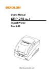
TP801/TP805/TP806 User Manual Desktop POS Printer TP801/TP805/TP806 User Manual TP801 TP805 TP806 Xiamen Hanin Electronic Technology Co.,Ltd. ADD: Room 305A,Angye Building, Pioneering Park, Torch High-tech Zone, Xiamen, China 361009 Tel.:+86-(0)592-5885993 Fax: +86-(0)592-5885992 Web: www.hprt.com www.hprt.com 1 TP801/TP805/TP806 User Manual REVISION RECORDS REV. DATE 1.0 2013.04.10 1.1 Drawn Checked Approved 1.Added the warnings of using crash drawer Chen weihua Lin yang Ren xiaowei 2013.04.19 1.Added the setting of Ethernet IP Chen weihua Lin yang Ren xiaowei 1.2 2013.04.20 1.Added the warnings of using power adaptor Chen weihua Lin yang Ren xiaowei 1.3 2013.04.23 1.Modified some error descriptions Chen weihua Lin yang Ren xiaowei 1.4 2013.05.11 1.Added the description of Parameters checking and resetting illustration of the Ethernet and Wi-Fi cards Chen weihua Lin yang Ren xiaowei 1.5 2013.06.01 1.Modified the packing list Chen weihua Lin yang Ren xiaowei 1.6 2013.11.05 1.Modified the printer’s driver Chen weihua Lin yang Ren xiaowei 2014.01.13 1.Added the description of Wi-Fi setting 2. Modified the description of print self-test page 3. Modified the layout of user manual Chen weihua Lin yang Ren xiaowei 1.7 www.hprt.com DESCRIPTION 2 TP801/TP805/TP806 User Manual CONTENTS Statement .................................................................................................................... 5 Important Safety Instructions ...................................................................................... 6 POS printer packing-case ............................................................................................. 7 1 Overview ................................................................................................................... 8 1.1 Introductions .................................................................................................. 8 1.2 The main features .......................................................................................... 8 2 Specification ............................................................................................................. 9 2.1 Printer specification ....................................................................................... 9 2.2 Printing media specification ......................................................................... 10 2.2.1 Continuous thermal paper specification ............................................ 10 2.2.2 Black mark paper specification .......................................................... 10 2.2.3 Notices .............................................................................................. 10 2.3 Printing and cutting position ........................................................................ 11 2.3.1 Printing position ................................................................................ 11 2.3.2 Cutting position ................................................................................. 11 3 Printer components ................................................................................................ 12 3.1 Appearance and component ........................................................................ 12 3.1.1 TP801 ................................................................................................ 12 3.1.2 TP805 ................................................................................................ 13 3.1.3 TP806 ................................................................................................ 14 3.2 Specification of Indicated light and beeper .................................................. 15 4 Printer packing ........................................................................................................ 16 4.1 Open packing ............................................................................................... 16 4.2 Choice installation site and direction of printer............................................ 16 4.3 Connect the printer power adaptor ............................................................. 16 4.4 Connecting the Interface Cable .................................................................... 17 4.5 Connecting the Cash Drawer ........................................................................ 17 4.6 Paper roll installation ................................................................................... 17 4.6.1 Confirmation of printing paper .......................................................... 17 4.6.2 TP801/TP805/TP806 installation/Change Paper ................................ 17 4.7 Setting DIP switch......................................................................................... 19 4.7.1 Serial interface(RS-232C).............................................................. 19 4.7.2 Interfaces of Parallel and USB2.0 ....................................................... 19 4.7.3 The choice of auto cutter................................................................... 20 4.8 Print self testing ........................................................................................... 20 4.9 Installation of Windows driver ..................................................................... 20 4.9.1 The driver installation instruction of USB /serial port /parallel interface ..................................................................................................... 20 4.9.2 The driver installation instruction of Ethernet and Wi-Fi ................... 22 www.hprt.com 3 TP801/TP805/TP806 User Manual 4.9.3 Parameters checking and resetting illustration of the Ethernet and WiFi cards ....................................................................................................... 24 4.9.4 Setting of Ethernet IP ........................................................................ 25 4.9.5 Wi-Fi settings ..................................................................................... 29 5 Interfaces signal ...................................................................................................... 40 5.1 Parallel interface .......................................................................................... 40 5.2 Serial interface ............................................................................................. 41 5.3 Power Supply interface definition ................................................................ 41 5.4 Cash Drawer interface signal ........................................................................ 42 5.5 Serial interface and Ethernet interface ......................................................... 42 6 Troubleshooting ...................................................................................................... 44 6.1 Printer not working ...................................................................................... 44 6.2 LED indicator on the control panel and beeper alarm .................................. 44 6.3 Troubles occur during printing ..................................................................... 44 6.4 Problems emerge during the paper cutting processes ................................. 45 6.5 Removing Jammed Paper ............................................................................. 45 www.hprt.com 4 TP801/TP805/TP806 User Manual Statement This manual content may be altered without permission, and Xiamen Hanin Electronic Technology Co., Ltd. reserves the rights to make changes without notice in technology, spare parts, hardware and software of the products. If more information is needed about the products, please contact Xiamen Hanin Electronic Technology Co., Ltd. Without any written permission from the company, any section of this manual is prohibited to be copied or transferred in any form. Copyright This manual is printed in 2013, the copyright belongs to Xiamen Hanin Electronic Technology Co. Ltd. Printed in China 1.0 Version Warnings : This must be complied with in order to avoid any damage to the human body and to the equipment. This is showing the important information and tips for the printer operating. www.hprt.com 5 TP801/TP805/TP806 User Manual Important Safety Instructions 1. Safety warning 1) Warnings: The print head will become very hot during printing; avoid contact with the print head after printing has finished. 2) Warnings: Do not touch the printer head and connector in case static damage the printer head. 2. Instructions Read the following instructions thoroughly before starting up your printer. 1) Place the printer on a solid and even base so that it cannot fall. 2) Leave enough space around printer for operation and maintenance. 3) Keep all liquids away from the printer. 4) Do not expose the printer to high temperatures, direct sunlight or dust. 5) Protect the printer from shock, impact and vibration. 6) Ensure the printer is connected to a socket with the correct mains voltage. 7) Switch off the printer power supply when won’t use it for a long time. 8) Do not printing when there is no paper, or it will damage printer head. 9) To ensure the printing quality and reliability, suggest use the same quality or recommend paper supplier. 10) Pls switch off the power supply when connect/disconnect all the ports or it will cause damage to the printer control circuit. 11) Never carry out maintenance or repair work yourself. Always contact a qualified service technician. 12) Keep this Operator’s Manual in a place which is easily accessible at all times. www.hprt.com 6 TP801/TP805/TP806 User Manual POS printer packing-case Pls. check you get all in carton as pic. 1 Power adapter Power line Quick start guide CD TP801 TP806 TP805 pic.1 www.hprt.com 7 TP801/TP805/TP806 User Manual 1 Overview 1.1 Introductions TP801/805/806 is a thermal receipt printer with auto-cutter, featured by high printing quality, high printing speed, high stability, etc. It can be used in commercial POS system, food industry and occasions which need real-time field print receipts. TP801/805/806 can connect with other equipments through parallel, serial, USB, and Ethernet interfaces. And the printer drivers are available for the WINDOWS XP/WINDOWS 7 32 bit/WINDOWS 7 64bit operating system. 1.2 The main features 1) 2) 3) 4) 5) 6) 7) 8) 9) Automatic paper cutting Low noise High printing speed Easy paper loading User convenient maintenance Support label paper and continuous paper printing Compatible with various width paper Cash drawer interface Communication interfaces optional www.hprt.com 8 TP801/TP805/TP806 User Manual 2 Specification 2.1 Printer specification Model Print method Resolution Printing width Printing Parameter Print speed TP805 RAM Flash Chinese Alphanumeric 203DPI,8dots/mm 72mm(576dots) 200~300mm/s 200~250mm/s Wi-Fi Serial, Parallel, Ethernet, USB Adjustable from level 1 to level 4 support 1Mb 4Mb GB18030 24×24 (Simplified/Traditional Chinese) ASCⅡ9×17,12×24. User-defined support Interface Print density Page Mode Memory TP801 Direct thermal line printing TP806 250~300mm/s Wi-Fi Optional international character sets 32: Fonts (PC437,Katakana,PC850,PC860,PC863,PC865,ABICOMP,PC857,PC737, Code page ISO8859-7 , WPC1252 , PC866,PC852,PC858,KU42,TIS11,TIS18,PC720 , WPC775 , PC855 , PC862 , PC864 , ISO8859-2 , ISO8859-15 , WPC1250 , WOC1251 , WPC1253,WPC1254,WPC1255,WPC1256,WPC1257,WPC1258) Support varied density bitmap as and download bitmap printing Max size of each bitmap is 40K, the total size of bitmap is 256k Graphics Barcode Detect Function LED Indicator Power Supply Paper 1D UPC-A、UPC-E、EAN8、EAN13、CODE39、ITF、CODEBAR、CODE128、CODE93 2D PDF417、QR code Paper end, paper near end, Paper end, paper near end Paper end, paper near end, take paper and cover open and cover open sensors paper jam and cover open sensors sensors Sensors Power indicator Green LED Paper indicator Blue LED Error indicator Red LED External power adapter Input AC100V-240V 50-60HZ DC 24V, 2A Output Paper type Standard Thermal Paper Paper width 79.5±0.5mm/57.5±0.5mm Paper thickness 0.056~0.1mm Paper roll diameter Max. OD ф83mm Paper load Paper cut Command Physical Spec. Reliability Software Function www.hprt.com Green LED Red LED Red LED Forward cover open and Easy Upward cover open and Easy paper loading paper loading Manual tear or Auto-cutter ESC/POS Operating condition -10℃~50℃,25%~80%RH Storage condition -40℃~70℃,≤93%RH(40℃) Dimensions 190×127 ×126mm 195×177×147mm L×W×H Weight TPH lifetime Cutter lifetime MTBF Driver program Green LED Red LED Red LED 1580g 1.8kg 150km 2,000,000 cuts 360, 000 hours Windows (Win7/Win8/Vistal/XP/2000) 197×145×146mm 1.8kg 9 TP801/TP805/TP806 User Manual 2.2 Printing media specification 2.2.1 Continuous thermal paper specification Paper type: thermal continuous paper/thermal black mark paper/thermal label paper. Paper width: 80±0.5 mm, 57.5±0.5 mm. Paper outer diameter:Max. 83 mm. Paper roller inner diameter:paper roll mandril inner diameter 12mm,paper roll mandril outer diameter 18mm. Paper thickness:0.065 ~ 0.10mm. 2.2.2 Black mark paper specification When using the black mark paper, the black mark paper must be at the front side of the receipt paper, and the reflectivity should be less than 15%, and the reflectivity of other part of the paper should be more than 85%. There must not be any graphics in the black mark space, such as advertising. The black mark should be qualified for the below requirement: 5mm<L1(black mark width)<10mm L2(black mark length)>12mm 20mm<L3(the distance between two black mark)<500mm Fig 2.2.1 2.2.3 Notices Notes: Pls. use the high quality thermal paper, otherwise it will influence the printing quality and decrease the thermal printer head life; Don’t stick the paper on the paper roll mandril; If the thermal paper is polluted by chemical or oil, the thermal paper heat sensibility decreases, which will influence the printing quality; Don’t use finger nail or hard articles to touch the surface o f thermal paper, otherwise it will cause color fading ; When the environment temperature is higher than 70°C, the thermal paper color will fade, so pay attention to the influence of temperature, humidity and sunlight. www.hprt.com 10 TP801/TP805/TP806 User Manual 2.3 Printing and cutting position 2.3.1 Printing position Fig 2.3.1 1) L1 Paper house width:TP801/805-83mm,TP806-81±0.5mm 2) L2 Valid printing width: 80mm 3) L3 The distance between the thermal printer head and the left side of the paper house(fixed width):3.5±0.3mm 4) L4 The distance between the thermal printer head and the right side of the paper house(fixed width):3.5±0.3mm 5) L5 The left side:default 4mm 6) L6 Printing width:decided by the command (see the program guide), and the default is 72mm. 7) L7 Te right side:default 4mm 2.3.2 Cutting position Paper feeding direction Cutting position Fig 2.3.2 www.hprt.com 11 TP801/TP805/TP806 User Manual 3 Printer components 3.1 Appearance and component 3.1.1 TP801 1.Printer Cover 2.Paper Detection 9.Feed LED 10.Cover Open Button 3.Paper Mouth 4.Front Cover 11. Flexible Interface Board (Serial/Parallel/Ethernet/Wi-Fi) 5.Power Switch 13.Cash Drawer Interface 6.Power LED 14.Power Interface 15.DIP Switch Cover 7.Error LED 8.Paper near end LED www.hprt.com 12.USB Interface 12 TP801/TP805/TP806 User Manual 3.1.2 TP805 1.Printer Cover 2.Paper Mouth 3.Front Cover 4.Power Switch 5.Power LED 6.Error LED 7.Paper nerd end LED 8.Feed LED www.hprt.com 9.Cover Open Button 10.Cable cover 11/12. Flexible Interface Board (Serial/Parallel/Ethernet) 13.USB Interface 14.Cash Drawer Interface 15.Power Interface 16.DIP Switch cover 13 TP801/TP805/TP806 User Manual 3.1.3 TP806 1.Printer Cover 2.Paper Mouth 3.Front Cover 4.Power Switch 5.Power LED 6.Error LED 7.Paper nerd end LED 8.Feed LED 9.Cover Open Button www.hprt.com 10.Flexible Interface Board (Serial/Parallel/Ethernet/Wi-Fi) 11.Rubber Pads 12.USB Interface 13.Cash Drawer Interface 14.Power Interface 15.DIP Switch cover 16.Waterproof Cover 17.Cable Cover 14 TP801/TP805/TP806 User Manual Specification of some part elements 1) Power switch Press “0” to turn off power and press “1” to turn on power supply; 2) Paper out indicator light Detect the status of paper .when warming light fast blink, it means paper will run out, you should change paper soon; Under this status, printer will keep working until paper out ; 3) Unusual indicator light During operation the if some abnormality has occurred, unusual light will flash, which indicates the printer is in an error state, should turn off power and check it . 3.2 Specification of Indicated light and beeper Function specification of Indicated light and beeper Name POWER Indicator light (Green) ERROR Indicator light (Red) PAPER Indicator light (TP801 Blue) (TP805/TP806 Red) Status Bright Extinguish Flashed Specification The printer work well The printer does not work The printer in an error state Extinguish The printer in an normal state TP801 Flashed Extinguish Description Open the cover of printer Full of paper No paper Paper will out The printer in paper out state TP805/TP806 Bright The printer in an normal state Power Unusual Paper out bright bright bright bright bright bright Extinguish bright Extinguish Extinguish bright bright Beeper Two short voice“ Beep ,Beep”,one long voice“ Beep” Silent Three short voice “Beep Beep Beep”. Silent Notes: The printer uses a thermistor to detect the temperature of the print head, if the print head is overheated, the circuit will cut off the power to the print head, and stop printing; The print head overheat protection temperature is 70 ° C www.hprt.com 15 TP801/TP805/TP806 User Manual 4 Printer packing 4.1 Open packing When opening the package, according to the packing list to check if items are missing or damaged, if so, please contact the dealer or manufacturer. 4.2 Choice installation site and direction of printer 1) Install the printer on a flat, stable place; recommend to install it at horizontal line, angle of inclination should not exceed ± 10 °(paper feed direction)if tilt install printer, it does not allow to tilt by other direction. 2) Keep printer far away from source of water; 3) Avoid the printer on place where it is vibration and shock 4) Ensure printer ground connect is sate; 5) When the printer is at operation and maintenance, it is recommended to retain the space as below to ensure the printer can work in reliability and ease of operation. 4.3 Connect the printer power adaptor 1) Make sure the printer's power switch is turned off; 2) Put the cable plug of power adapter facing up at flat side, insert the rear of the printer power connector; 3) Turn the power adapter input power; 4) Pay attention about disconnecting or connect the AC adapter at right method, or likely to cause damage. The plug of power adapter is designed in a switch type, when accessing power adapter and uttered the voice "click", it means the connected socket switch is locked the adapter connect well, otherwise please connect again . When pull out the adapter, please pinch the shell of power adaptor and pull the switch up, when the switch is fully opened then pull out the power adapter. Don’t put forth your strength to pull the plug by squeeze at any of place of power adaptor .Because, it is more difficult to pull it out and easy to damage the cable. www.hprt.com 16 TP801/TP805/TP806 User Manual Notes: ► Please only use the power adapter are recommended by supplied or equivalent products; ► When disconnecting the AC adapter plug, handheld plug connector housing, to avoid the pulling on the cable in force; ► Avoid drag the power adapter cable, otherwise it will damage the cables, causing fire and shock; ► Avoid put power adapter around a heating device, otherwise the cable may melt, causing fire and shock; ► If you do not use the printer in a long time, disconnect the power supply of printer power adapter. 4.4 Connecting the Interface Cable 1) Make sure the printer's power switch is turned off; 2) Put the interface cable into the matched interface and fixed with screws (or spring) on the plug; 3) Connect the other end of the interface cable to the host. 4.5 Connecting the Cash Drawer 1) Make sure the printer's power switch is turned off; 2) Connect the cash drawer cable into the cash drawer interface on the rear side of the printer. Warning: Cash drawer interface can only be connected to a voltage of 24V cash drawer device (can’t connect to the phone line, etc.) 4.6 Paper roll installation 4.6.1 Confirmation of printing paper After connecting the power adapter and interface cable, you can install media for printing. Confirm the type of paper used by the printer before printing. The default paper type is continuous paper. If you need to set the marked paper, please contact your dealer or manufacturer. 4.6.2 TP801/TP805/TP806 installation/Change Paper 1) Turn off printer power supply; 2) Flipping switch knob, open the top cover of TP805\TP806 and front cover of TP801(Like figure 4.6.1) www.hprt.com 17 TP801/TP805/TP806 User Manual TP806 TP805 TP801 Figure 4.6.1 3) Put the paper into printer(Like figure 4.6.2) TP805 TP806 TP801 Figure 4.6.2 Notes: ► According to the paper size to adjust the paper holder; ► Make sure the end of the paper roll fit for the graphics requirements; Figure 4.6.3 ► Make sure the paper inside is at tight status, or it will tissue paper or other obstacle. 4) Pull out of the end of paper roll, closed the cover and tear up sheet of paper. www.hprt.com 18 TP801/TP805/TP806 User Manual 4.7 Setting DIP switch 4.7.1 Serial interface(RS-232C) ·DIP switch 1 Switches 1-1 1-2 1-3 1-4 1-5 1-6 1-7 Functions Line feed automatic Handshaking Data length Odd-even verify Odd-even choice Turn on Yes XON/XOFF 7 bit Yes EVEN Turn off Prohibit DTR/DSR 8 bit No ODD Default Turn off Turn off Turn off Turn off Turn off Turn off Turn on Reference form 1 Choice baud rate(bps) 1-8 Turn off DIP switch 2 Switches 2-1 2-2 2-3 Functions The mode switch in both Chinese and English Internal control beeper Auto cutter 2-4 2-5 2-6 2-7 2-8 Busy condition Turn on Turn off Default English Chinese Turn on Permit Prohibit Prohibit Permit *Off-line * Receive buffer is full Turn off Turn off Receive buffer is full Printer density Paper out sensor status Turn off Turn off Turn off Turn off Reference form 2 Prohibit Turn off Permit 4.7.2 Interfaces of Parallel and USB2.0 DIP switch 1 Switches 1-1 1-2~1-8 Function Line feed automatic Reserve Turn on Permit - Turn off Prohibit - Default Turn off Turn off DIP switch 2 Switches 2-2 2-3 Functions The mode switch in both Chinese and English Internal control beeper Auto cutter 2-4 Busy condition Receive buffer is full 2-1 2-5 2-6 2-7 2-8 www.hprt.com Turn on Turn off Default English Chinese Turn on Prohibit Prohibit Permit Permit *Off-line * Receive buffer is full Turn off Turn off Printer density Paper out sensor status Reference form 2 Prohibit Permit Turn off Turn off Turn off Turn off Turn off 19 TP801/TP805/TP806 User Manual Form 1—The Choice of Baud rate Baud rate 2400 4800 9600 19200 38400 57600 115200 1-6 Turn on Turn on Turn off Turn off Turn off Turn off Turn on 1-7 Turn off Turn off Turn on Turn off Turn on Turn off Turn on 1-8 Turn off Turn on Turn off Turn off Turn on Turn on Turn on Default 9600 Form 2—The choice of print density 2-5 2-6 2-7 Printer density Turn on Turn on Reserve Turn off Turn on Turn off Turn off Reserve Reserve 1(diluted) 2 3 Turn off Turn on Reserve 4(dense) Default 2 4.7.3 The choice of auto cutter Switch2-3 Application program DIP Switch setting 2 Turn on Automatic paper cutting is prohibited Turn off Automatic paper cutting is permitted Ignore the automatic paper cutting error continuous printing 4.8 Print self testing 1) Make sure the printer has been installed paper roll and turn off the top cover; 2) Press on FEED button and turn on power switch, the printer will print out self-test page. 4.9 Installation of Windows driver Give an example of TP806, in printer’s CD has attached windows driver program, open the driver program and run “DriverSetup.exe”. 4.9.1 The driver installation instruction of USB /serial port /parallel interface 1) Double click” HPRTTPPrinterDriver-v-1.0.2.6.exe”, Choice “English” and click “OK”. www.hprt.com 20 TP801/TP805/TP806 User Manual 2) Click “Install”. 3) Choice the port and type you want(the installation program will recognize the usable printer ports automatically, USBxxx is for USB port ,COMx is for serial port,LPTx is for parallel port),click “Next” to next step. 4) Click “Finish” , it is successful to install. www.hprt.com 21 TP801/TP805/TP806 User Manual 4.9.2 The driver installation instruction of Ethernet and Wi-Fi 1) Install printer driver program just as USB installation. 2) Click “Control Panel”→”Hardware and Sound”→”Devices and Printers”. 3) Right click “HPRT TP806” and choice “Printer properties”, click “Ports”,choice”COM1”, Click “Add Port…” button. 4) Choice “Standard TCP/IP Port” and click “New Port…” button. www.hprt.com 22 TP801/TP805/TP806 User Manual 5) Click “Next>”. 6) Finishing the writing of printer name (or IP address)and port name ,Clicking “Next >”. “Printer Name or IP Address”: Depends on the display of printer’s self-test page. “Port Name”: Users can customize the name of the port. 7) Clicking “Next >”. www.hprt.com 23 TP801/TP805/TP806 User Manual 8) Click “Finish”. 9) Click Click “Control Panel”→”Hardware and Sound”→”Devices and Printers”., right click “Printer Properties” of printer HPRT TP806 and choice “Ports”→“Configure Port…”, finish the setting of related parameter, click “OK”. 4.9.3 Parameters checking and resetting illustration of the Ethernet and Wi-Fi cards Ethernet parameter checking: Press the button on the communication card round hole when the printer is power on, the printer will print the current Ethernet parameters. Ethernet card parameter resetting: Press the button on the communication card round hole then power on. After you power on, the parameter on the communication card is renew to the original situation. www.hprt.com 24 TP801/TP805/TP806 User Manual Wi-Fi card parameter checking: Press the button on the interface card round hole when the printer is power on, he printer will print software edition and the TCP/IP setting information of the interface card. Wi-Fi card parameter resetting: Press the button on the communication card round hole then power on. he parameter on the communication card is renew to the original situation. 4.9.4 Setting of Ethernet IP 1) Ethernet IP can be set through Web page, the operating steps are followed: 2) Connect the printer to computer, please refer to the USB, Serial interface and Parallel User Manual 4.9.1. 3) Connect Ethernet to the printer, please refer to the Ethernet driver installation in User Manual 4.9.2. 4) Print self- test page after power on. You can find the IP information in the self-test page IP address line. IP address: 192.168.0.31 //indicates the IP address is 192.168.0.31 5) Click Start-Operate in the computer and key in “cmd” in the input box then click Sure, see the following figure: 6) Key in ping 192.168.0.31 after “Administrator>”, see the following figure: www.hprt.com 25 TP801/TP805/TP806 User Manual 7) Click “Enter”, if the following figure is presented, you can sure that the Ethernet have been connected to the printer, if not presented, please check the connection between the Ethernet and the printer. 8) Then please input http://192.168.0.31, in the brower see the following figure: www.hprt.com 26 TP801/TP805/TP806 User Manual 9) Press “Enter”, the browser will skip to the IP setting interface, click Configuration in the left side then enter to the address modify page, 192.168.0.31 is the current IP address, see the following figure: 10) Modify the IP in the IP Address. For example, modify the IP to 192.168.0.32,see the following figure: www.hprt.com 27 TP801/TP805/TP806 User Manual 11) Click SUBMIT in the middle of the upper page then enter to the following webpage: 12) Click RESET in the middle of the upper webpage then enter to the following webpage: www.hprt.com 28 TP801/TP805/TP806 User Manual 13) Reboot the printer to effect the new IP, then you can print self-test page and find the new IP address 192.168.xx.xx. 4.9.5 Wi-Fi settings Wi-Fi work mode: AP mode:when printer under AP mode, it works as an access point. STA mode: when printer under STA mode, it works as a wireless terminal, which could find and connect to AP. To allow users to conveniently make WIFI setting change, AP mode has been set to default. User could use PC to connect to the printer by web browser. After entering WIFI setting page, users could switch to STA mode accordingly and make other setting changes, for example IP address, SSID. 1. Entering Wi-Fi setting page: 1) Power on the printer. 2) Enable Wi-Fi on the PC, and search for “TP806_WIFI”. www.hprt.com 29 TP801/TP805/TP806 User Manual 3) Open web browser, and enter http://192.168.0.XXX( this IP address is printed on the Wi-Fi configuration page). How to print Wi-Fi configuration page: power on the printer, long press the WIFI reset button (see below picture), then printer will print the configuration page. NOTE: hold Wi-Fi reset button, at same time power on the printer, Wi-Fi settings will be set to factory default. Example of Wi-Fi configuration page, which shows the IP address of 192.168.0.33. www.hprt.com 30 TP801/TP805/TP806 User Manual 4) Use Internet Explorer or other web browser to open http://192.168.0.33, input user name: admin; password: admin 5) After entering user name and password, click on OK to enter Wi-Fi setting page. www.hprt.com 31 TP801/TP805/TP806 User Manual 2. STA mode settings 1) Click on “Work Mode” on the left-hand side, rolling down to STA mode. 2) Click on “SAVE” and below window will pop up. www.hprt.com 32 TP801/TP805/TP806 User Manual 3) Do not click on “RESTART” button at this moment, instead click on the “STA Setting” on the left side to make more STA settings. 4) Click on “SCAN” button to search for access points For example, below picture shows there are several access points available www.hprt.com 33 TP801/TP805/TP806 User Manual 5) Choose the correct access point. For example: ”embedded” , see below picture. www.hprt.com 34 TP801/TP805/TP806 User Manual NOTE: settings in the above pictures are just for examples, not for your actual onsite network settings. Please refer to your IT and network engineer for the correct network settings. www.hprt.com 35 TP801/TP805/TP806 User Manual 6) After setting, click on “SAVE”. 7) If users want to make other changes, click on “ BACK” , otherwise click on “RESTART” button. 8) Above settings will take into effect after power off/on the printer, user could print the Wi-Fi configuration page to check whether settings have been success fully made. www.hprt.com 36 TP801/TP805/TP806 User Manual NOTE: after changing to STA mode, access point will assign an IP address to the printer, by printing WIFI configuration page, users could see the IP address, and use it for entering WIFI setting page in the future. 3. AP mode settings: 1) Click on the “Work Mode”, roll down to “AP mode”, click on “Save”. 2) Do not click on “Restart”, and instead click on “AP Setting” on the left side. www.hprt.com 37 TP801/TP805/TP806 User Manual 3) According to user’s actual needs to change network mode, SSID, IP address and other settings ( please refer to IT or network engineer for the correct settings). 4) Click on “Save” and “restart” button to confirm the settings. www.hprt.com 38 TP801/TP805/TP806 User Manual 5) Power off and power on the printer, above settings will take into effect. Users could print WIFI configuration page to check whether setting have been successfully made. www.hprt.com 39 TP801/TP805/TP806 User Manual 5 Interfaces signal Printer TP801/TP805/TP806 supports cash drawer interface and many other various communicate interfaces, such as Serial interface, parallel interface, USB interface, Ethernet interface (TP801/TP806 also support Wi-Fi interface). The printer has the communication board with the default USB interface and cash drawer interface, and the other communication boards with the Ethernet interface, parallel interface, RS232 interface are optional. 5.1 Parallel interface Parallel interface (TP801/TP805/TP806 support TM-T88IV protocol) supports protocol with 36 pin CENTRONICS socket. 1 Signal Source H Data latch pulse, latch the data to the printer at the rising edge of the negative pulse 2 H Data 0(The lowest bit) 3 H Data 1 4 H Data2Si 5 H Data3 6 H Data4 7 H Data5 8 H Data 6 9 H Data7 (The highest bit) 10 P 11 12 P P Busy Signal; The printer is busy; High level indicates that the printer can’t receive data. PE Signal; paper end signal; High level indicates that the printer is paper end. 13 - Unconnected 14 - Unconnected 15 - Unconnected Pin No. Frame Ground, separated from logic ground 17 - Unconnected Logic Ground 19~30 31 Printer response signal, indicates that the printer has received the last byte of data; A negative pulse of about 1us. Logic Ground 16 18 Signal Definition - 32 P Unconnected Printer error signal, low level indicates that error occurs in the printer, the error signal will output along with paper end signal. Logic Ground 33 34~35 - Unconnected 36 - Unconnected www.hprt.com 40 TP801/TP805/TP806 User Manual Note:H indicates that signal comes from Host computer, P indicates that signal comes from Printer Figure 5.1.1 5.2 Serial interface Pin definition PIN No. 1 Signal name VBUS Classic wire color Red 2 D- White 3 D+ GND Green Black 4 Figure 5.2.1 5.3 Power Supply interface definition 1) Pin definition PIN No. 1 2 3 SHELL Signal Name +24V GND N.C F.G Figure 5.3.1 2) Interface type Printer end-Unetop DC-002 or similar products, user end-Unetop DC-002 or similar products www.hprt.com 41 TP801/TP805/TP806 User Manual 5.4 Cash Drawer interface signal 1) Electrical characteristics Driving voltage:DC 24 V Driving current:maximum 0.8 A ( In 510 ms) Drawer check signal:“L” = 0~0.5 V “H” = 3~5 V 2) Cash Drawer interface sing RJ-11 connector Figure 5.4.1 Interface signal definition Pin No. Signal Function 1 FG Frame Ground 2 DRAWER 1 Drawer kick-out drive signal 1 3 DRSW Drawer open/close signal 4 VDR Drawer driving source 5 DRAWER 2 Drawer kick-out drive signal 2 6 GND GND Note: Strictly prohibit to hot plug the plug. When arranging the line of communication, you have to avoid paralleling with the strong current. you have to use the shielded communication line. 5.5 Serial interface and Ethernet interface Printer TP 805 serial interface is compatible with RS-232 standard, with 9 pin (D hole type) socket. www.hprt.com 42 TP801/TP805/TP806 User Manual Serial interface definition Ethernet interface definition PIN No. Signal definition PIN No. Signal definition PIN 1 CD 1 TX+ PIN 2 TD 2 TX- PIN 3 RD 3 RX+ PIN 4 DSR 4 n/c PIN 5 GND 5 n/c PIN 6 DTR 6 RX- PIN 7 CTS 7 n/c PIN 8 RTS 8 n/c PIN 9 RI Printer TP 801 and TP806 serial interface are all compatible with RS-232 standard, with 25 pin (D hole type) socket. User can gain the setting of interface via printing configuration sample; the default setting of serial interface is as follow, 9600 bps (baud rates), 8 bit (data bit), 1 bit (stop bit), no parity, support RTS/CTS handshaking protocol. Serial interface definition Ethernet interface definition PIN No. Signal definition PIN No. PIN1 Signal definition Frame Ground 1 TX+ PIN2 TXD 2 TX- PIN 3 RXD 3 RX+ PIN 4 RTS 4 n/c PIN 5 Unconnected 5 n/c PIN 6 DSR 6 RX- PIN 7 GND 7 n/c PIN 8~19 Unconnected 8 n/c PIN 20 DTR Unconnected PIN 21~25 TP805 TP801/TP806 Figure 5.4.1 www.hprt.com 43 TP801/TP805/TP806 User Manual 6 Troubleshooting Your printer is very reliable, but occasionally problems may occur. This chapter provides information on some common problems you may encounter and how to solve them. If you encounter problems that you can not resolve, contact your dealer for assistance 6.1 Printer not working Problem description LED indicator not light, printer not working Probable reason Solution Printer No power Connecting the power supply Printer not on Turn on the printer Circuit board broken Contact with the dealer 6.2 LED indicator on the control panel and beeper alarm Problem description Probable reason Solution Paper LED always on Paper near end Error LED always on and beeper alarms Printer Cover open Close the printer cover Paper Error LED always on and beeper alarms Paper end Reload the roll paper The roll paper is near end, the printer can work normally Thermal print head overheated Turn the printer off and resume when it cools Error LED blinks and beeper alarms overvoltage Print with specified voltage Low-voltage Print with specified voltage 6.3 Troubles occur during printing Problem description Coloured stripe in the paper Blurred printing or spot Paper Jam Vertical print words missing www.hprt.com Probable reason Paper near end Incorrect roll paper installation Unqualified roll paper Dirty thermal head or print rooler Low print density Dirty thermal head or print rooler Solution Reinstall the roll paper Check if the roll paper is installed Use recommended thermal roll paper Clean the thermal head or print rooler Increase the print density level Open the printer cover, check the paper path and remove jammed paper Clean the thermal head or print rooler Thermal head damaged Contact your dealer for assistance Paper stucked 44 TP801/TP805/TP806 User Manual 6.4 Problems emerge during the paper cutting processes Problem description Probable reason Resolution Cutter abrasion, insufficient replace the cutter cutting Cutter jam, the movable cutter cannot back Insufficient cutting Worm gear and worm wheel Replace the worm gear and worm wheel abrasion Motor burnt Replace the motor Paper scraps Clean the paper scraps on the transmission system Cutter edge abrasion, paper Replace the cutter too thick Thermal printer head over heat Reduce the thermal printer head heating power Driving too fast Reduce the printer speed to the limit of thermal printer head Wrong paper feeding position Put the paper parallel with the paper mount and insert into the space between platen roller and the thermal printer head Paper jam 6.5 Removing Jammed Paper Do not touch the thermal print head because it becomes very hot after printing. Turn the printer off and press the cover open button. Remove jammed paper, reinstall the roll, and close the cover. www.hprt.com 45 TP801/TP805/TP806 User Manual If the auto cutter jam occurs on printer TP805 and TP806 and you cannot open the printer cover, open the cutter cover as shown on the left below. Turn the knob until the cutter blade returns to the normal position. Close the cutter cover. Open the printer cover and remove the jammed paper. TP805 www.hprt.com TP806 46