1
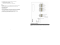
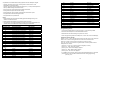
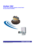
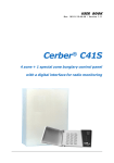
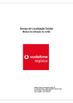
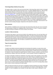
GSM-11T
Table of contents
GENERAL FEATURES…………………………………………………...3
Applications of the GSM-11T communicator......................................... 3
Functions of GSM-11T communicator................................................... 4
Functioning modes of the GSM-11T communicator .............................. 4
GSM communicator
TECHNICAL FEATURES………………………………………………...5
DTMF communication formats of the alarm control panel..................... 5
Available inputs and outputs .................................................................. 5
Functioning indicators ............................................................................ 5
Consumption .......................................................................................... 5
GSM network specifications .................................................................. 6
INSTALLATION………………………………………………………….6
GSM module installation........................................................................ 6
GSM module programming.................................................................... 8
Hook up, Installation and Programming Manual
Doc. 10112/ version 2.0
2
GENERAL FEATURES
GSM-11T communicator can be used as an accessory for a burglary control panel with
digital communicator or as a stand-alone alarm unit. It is made up of one GSM module and
a GSM phone from Ericsson family (see „Usable GSM phones”).
GSM-11T communicator can be connected to a burglary control panel, as backup for the
telephone line in case it is faulted, or directly, in case of missing telephone line. Thus, the
communicator provides a higher security level for objectives protected by burglary alarm
systems.
In case the control panel transmits events (in DTMF formats), the GSM module receives
and codifies them, while the GSM phone transmits them to the GSM monitoring station,
which must have a GSM interface. This GSM interface decodes the signal transmitted by
the communicator GSM phone. The GSM interface is produced by Romano Electro
Company, as an accessory for the Xwatch DPC-08 monitoring station.
The owner of the burglary alarm system can optionally get SMS-formatted event
description on his/her own GSM phone.
GSM-11T communicator can be used in all GSM telephone networks, selected through the
acquired SIM card.
GSM-11T communicator is totally compatible with the burglary control panels in Cerber,
XL, Paradox families, etc.
Parameter programming is performed by means of the GSM phone.
Applications of the GSM-11T communicator
GSM-11T communicator was designed to be used in one or several situations below:
- an alarm system with a digital communicator can function more securely if an GSM-11T
module is added. This module notices if the phone line is missing (by accident or
intentionally) from the alarm system, takes the control panel’s events and drives them to a
GSM monitoring station (phone line back-up). Thus, the alarm system is never vulnerable
and will transmit any event to the monitoring station in real time;
- an objective protected by an alarm system with digital communicator, for which a phone
line is not available (remote villas, depots) can report system events to a monitoring and
intervention for a lower cost compared to the radio monitoring;
- an application for event transmission regarding some inputs status when no alarm system
is needed (panic buttons, etc.);
- an application for input remote control, using the own mobile phone (turning on
central heating, light, etc.) – under construction.
Note: for the first 3 cases, appropriate events can be transmitted not only to a monitoring
station but also onto the own mobile phone, through clear messages in SMS format –
example: “for the objective with code 0261, an alarm was detected on zone 2, disarm by
code 1.”)
The next image describes functions of this communicator:
3
Functions of GSM-11T communicator
The digital GSM communicator performs several functions:
- detects loss and restoring of the phone line which the burglary control panel is connected
to, and forwards these events;
- supervises the phone line; in case that one gets faulted, the communicator will generate
the line tone, taking the events occurred at the control panel and retransmitting them
through the GSM network:
- in digital format, to a GSM interface monitoring station
- optionally, clearly, as SMS messages, onto a different mobile phone (i.e. on the
mobile phone of the burglary control panel-protected objective’s owner);
- provides 6 individual inputs to which sensors can be connected (burglary, fire, etc),
allowing the independent usage of the GSM communicator when the burglary control
panel is missing;
- transmits a periodical test, with a programmable period;
- transmits a code in case of weak GSM signal;
- detects mobile phone shutting down and commands its turning on.
Functioning modes of the GSM-11T communicator
GSM-11T communicator can function in 3 ways:
- it transmits events occurred at the objective protected by the burglary control panel only
to a GSM monitoring station (Xwatch DPC-08);
- it transmits events occurred at the objective protected by the burglary control panel only
as SMS messages to the mobile phone of the objective’s owner;
4
- it transmits events occurred at the objective protected by the burglary control panel both
to a monitoring station and as SMS messages as well, to the mobile phone of the
objective’s owner.
Define the phone number of the monitoring station and/or of the mobile phone of the alarm
system’s owner within the configuration SMS in order to select the functioning mode.
Events generated by the burglary control panel are taken and forwarded to the monitoring
station and/or the mobile phone of the client. The message containing these events also
contains the control panel’s account number.
If the regular phone line is present, the events are directly sent on the phone line (being
ignored by the communicator). If the regular phone line is not present, the events are taken
by the communicator and redirected through GSM.
The events generated by the communicator are: phone line loss/restoring, communicator’s
local inputs activation/deactivation, weak GSM signal and periodical test. A 4 HEX digit
account number should be defined for these events. These events (generated by the GSM
communicator) are transmitted through GSM, irrespective of the phone line status.
TECHNICAL FEATURES
DTMF communication formats of the alarm control panel
- ADEMCO Express 4x2;
- Contact ID (PID)
Available inputs and outputs
- 6 inputs with programmable codes for activation and deactivation;
- 6 “open collector” outputs, used for automations (upon construction).
Functioning indicators
The module has got a green signaling LED, indicating GSM phone presence and proper
functioning;
Consumption
- supply voltage:
- maximum taken current (including GSM phone loading):
- average taken current (loaded GSM phone):
11...13,8Vdc;
500mA;
40mA.
Notes:
1. The GSM phone connected to the GSM module is loaded from the module.
2. The GSM module will be loaded from the burglary control panel (if the latter can supply
500mA) or from a different power supply (i.e. SC-3).
5
GSM network specifications
- can be used in any GSM authorized network
Usable GSM phones:
- Ericsson A1018s
Other technical features
- average duration of GSM communication:
- active inputs by:
- maximum current at “open collector” outputs:
8s;
GND;
500mA.
WARNING:
For this present version, the software in the GSM communicator does not allow using the
GSM phone connected to the GSM module (in function) for vocal phone communications.
Hence, if this GSM phone is used simultaneously for conversations, the proper functioning
of the GSM communicator is no longer assured. The mobile phone of the communicator
is recommended to be used for this application exclusively. Its client number must not
be disclosed as someone could call it. However, if the phone must be used for an
emergency, the phone should be programmed as the client number is not displayed on the
called phone display.
The GSM hardware was designed to allow more developed versions of the software (free
of charge upgrades) in the future. These versions will allow implementations of automation
commands on the present hardware (6 outputs at the most), and remote process
supervision (6 inputs at the most).
The present software version of the GSM communicator allow its usage together with
Xwatch DPC-08 monitoring station produced by Romano Electro, and SMS message
transmission on the mobile phone of the burglary control panel protected objective’s owner.
GSM phones with versions older than 1999 must not be used. The software version of the
mobile phone can be read if successively pressing the next keys: “Æ” “*” “Å” “Å ” “*” “Å ”
“*”.
INSTALLATION
The GSM module will be connected between the burglary control panel and the GSM
phone.
GSM module installation
The connectors’ order, from left to right, is the next:
- 6 pin connector: the cable is connected to the GSM phone;
- 6 pin detachable connector:
- yellow wires will be connected to the phone line connectors of the burglary control
panel;
- the red wire will be connected to the +12V power supply (i.e.: Uaux: 11V … 14V);
- the black wire must be connected to ground;
- blue wires must be connected to the phone dose;
6
- 8 pin detachable connector for automation outputs (upon construction);
- input detachable connector in 2 variants:
- 3 pins - ground and 2 inputs (black, white, white)
- optional, 7 pins – ground, and 6 inputs – for input extension.
Note:
If the green LED does not turn on or the GSM communicator is supposed not to function,
do the next:
1. disconnect the GSM module and the GSM phone (connectors JP1 and JR1);
2. shut the GSM phone down;
3. wait for at least 10 seconds;
4. restart the GSM phone;
5. check if the local SMS message in the GSM phone can be read. In case a “Please wait”
or similar type message does not show up, wait for 5 seconds and try to read the SMS
message again. This sequence will be repeated until the SMS can be read.
6. connect the phone to the GSM module (connector JR1) and the GSM module
(connector JP1). The green LED should turn on (after 2…8s).
GSM module programming
Note: Before programming the GSM module, program the burglary control panel to phone
line transmit events in DTMF formats (Ademco Express or Ademco PID) to the monitoring
station.
7
8
All parameters of the GSM module will be programmed from the GSM phone keypad:
- optionally, the phone number of the monitoring station in case events are to be
transmitted to the monitoring station;
- optionally, the phone number of a different mobile phone (i.e. of the protected objective’s
owner) for SMS messages associated to events;
- client’s account for events generated by the GSM communicator;
- codes generated for phone line loss and restoring;
- codes generated in order to activate / deactivate the communicator’s inputs;
- code generated to make the GSM signal weaker;
- code generated for the periodical test.
Notes:
1. SMS messages are implicit and automatically generated. Message issuing is not
allowed in this software version.
2. SMS messages are available only for Ademco Express 4x2 format.
3. The meaning of sent codes associated to the events occurred was implemented in this
software version of the GSM communicator, according to the table below:
Event and
zone/user code
F9
E9
FB
Trouble
Restoring
Trouble
Siren loss
Siren restoring
Phone line loss
EB
1x
Restoring
Fire
Phone line restoring
Fire alarm
2x
3x
4x
Panic
Burglary
Medical emergency
Panic
Alarm on zone x
Medical emergency
5x
6x
9x
Bx
Cx
Ex
Fx
Others
Tamper
Bypassed zone
Periodical Test
Disarming
Arming
Restoring
Trouble
Ambush
Bypass zone x
Periodical Test
Disarm by code x
Arm with code x
Zone x restoring
Trouble on zone x
Unknown code
X = zone or user number
Event denomination
SMS message
00
01
02
communicator input 1 activation
communicator input 1 deactivation
communicator input 2 activation
TRIG1 ON
TRIG1 OFF
TRIG2 ON
03
04
05
communicator input 2 deactivation
communicator input 3 activation
communicator input 3 deactivation
TRIG2 OFF
TRIG3 ON
TRIG3 OFF
06
07
communicator input 4 activation
communicator input 4 deactivation
TRIG4 ON
TRIG4 OFF
08
09
0B
0C
0D
network
F0
E0
F7
E7
F8
E8
communicator input 5 activation
communicator input 5 deactivation
communicator input 6 activation
communicator input 6 deactivation
GSM signal weakening
TRIG5 ON
TRIG5 OFF
TRIG6 ON
TRIG6 OFF
trouble with the GSM
Trouble
Restoring
Trouble
Restoring
Trouble
Restoring
AUX loss
AUX restoring
220V loss
220V restoring
Discharged battery
Loaded battery
9
Programming mode:
1. Disconnect the GSM module from the power supply, if it was previously loaded.
2. Disconnect the GSM phone from the GSM module connector;
3. Deactivate the PIN code according to the phone user manual;
4. Enter the programming mode of the GSM phone, in menu “Mail”, then “Send Message”;
Example for Ericsson A1018s:
Buttons “Å” and “Æ” are for scrolling command menus and sub-menus on the same level.
Button “Yes” is used for entering the submenus of the current command menu.
Button “No” is used to exit the current menu and return to the main menu.
Keys “Yes” and “No” are for positive or negative answers to current questions that the
GSM phone user is asked.
- press keys “Å ” then “Yes” in order to unlock the keypad (if the case);
- press key “Å ” twice. Menu “Mail” appears.
- press key “Yes”. Menu “Read messages” appears.
- press key “Æ”. Menu “Send message” appears.
- press key “Yes”. Sub-menu “New” appears.
- if the GSM phone has not been used to program the GSM module before or if the GSM
phone does not contain any SMS for GSM communicator setting (programming):
- press key “Yes”.
10
- if the GSM communicator is reprogrammed or if there is a GSM module programming
SMS in the GSM phone:
- press key “Æ” once or several times until the configuration SMS appears on the
display;
- press key “Yes”.
5. in this case, a configuration SMS will be created, having the next structure:
- the phone number of the monitoring station (it can miss in case events are not
to be transmitted to the monitoring station)
- , (comma)
- the phone number for SMS messages (it can miss in case SMS messages are
not to be transmitted)
- , (comma)
- client’s account (4 HEX digits)
- , (comma)
- code generated by phone line loss (2 HEX digits)
- , (comma)
- code generated by phone line restoring (2 HEX digits)
- , (comma)
- code generated by activation (ground connecting) of the first communicator
input (2 HEX digits)
- , (comma)
- code generated by deactivation of the first communicator input (2 HEX digits)
- , (comma)
- code generated by activation (ground connecting) of the second
communicator input (2 HEX digits)
- , (comma)
- code generated by deactivation of the second communicator input (2 HEX
digits)
- , (comma)
- code generated by activation (ground connecting) of the third communicator
input (2 HEX digits)
- , (comma)
- code generated by deactivation of the third communicator input (2 HEX digits)
- , (comma)
- code generated by activation (ground connecting) of the fourth communicator
input (2 HEX digits)
- , (comma)
- code generated by deactivation of the fourth communicator input (2 HEX
digits)
- , (comma)
- code generated by activation (ground connecting) of the fifth communicator
input (2 HEX digits)
- , (comma)
- code generated by deactivation of the fifth communicator input (2 HEX digits)
- , (comma)
11
- code generated by activation (ground connecting) of the sixth communicator
input (2 HEX digits)
- , (comma)
- code generated by deactivation of the sixth communicator input (2 HEX digits)
- , (comma)
- code generated by GSM signal weakening (2 HEX digits)
- , (comma)
- code generated by the periodical test (2 HEX digits)
- , (comma)
- duration (in hours) the periodical test is performed at (2 decimal digits)
- . (period)
Note: All fields previously defined will be filled in, but the phone numbers (eventually). If
the first phone number (of the GSM monitoring station) is present in the configuration SMS,
the communicator will transmit certain events to the monitoring station. If the second phone
number is programmed, the communicator will transmit SMS messages to this second
phone number.
A typical example of a configuration SMS message:
0744111111,0744212223,123A,FB,EB,00,01,02,03,04,05,06,07,08,09,0B,0C,0D,90,10.
By this SMS, the GSM communicator is programmed to transmit its own and the burglary
control panel generated event codes to the monitoring station with the phone number
0744111111. SMS messages associated to events will be transmitted onto the mobile
phone number 0744212223.
Codes generated by the burglary control panel will keep the client’s account number
settled in the control panel. Events generated by the communicator will have the account
number 123A.
Upon phone line loss and phone line restoring, respectively, the communicator will
generate codes FB and EB, having the account number 123A.
Upon activation, deactivation of the 6 inputs of the communicator, codes 00, 02, 04, 06, 08,
0B, and 01, 03, 05, 07, 09 and 0C, with account number 123A, will be generated.
Upon GSM signal weakening, the interface will transmit code 0D settled in the
configuration SMS to the monitoring station.
The interface transmits code 90 for the periodical test. The duration for the periodical test
performing is 10 hours.
Note: Changing codes associated to events in the configuration SMS, will trigger the
appropriate interpretation of events associated to these codes. For example, if the 6th
parameter is programmed 38 instead of 00, then, upon activation of the first communicator
input, an „Alarm on zone 8” SMS type will be transmitted (instead of TRIG1 ON), while the
monitoring station will consider the event of the same type. Any change of the configuration
SMS is accompanied by a restart of the GSM module.
12
Note:
Format DTMF 4x2 describes events in such a manner that necessary information is
presented by means of 6 HEX digits “AAAAEZ”, where:
- “AAAA” is the client’s account number;
- “E” is the event code;
- “Z” is the zone/user number
For format Ademco PID, the interface will not generate clear SMS messages.
Notes:
In the edit mode, digits can be obtained directly, by pressing the corresponding keys
longer.
The comma and period can be obtained by successively pressing key “1”.
Upon editing, each key is used for several symbols: i.e. letter „C” is obtained by
successively pressing key “2” for 3 times.
Press shortly key “*” in order to switch from capital to small letters or vice versa; “*” also
modifies the last edited character from capital to small letter or vice versa.
Keys “Æ” and “Å” are used to move the slide to the right and left within the edited
message. By long pressing these keys, the slide is directly moved to the beginning or end
of the edited message.
Key “CLR” (Clear) is used to delete the character on the right or left of the slide.
6. Save this SMS, with no destination phone number, in the phone memory (not the
card’s);
Example for Ericsson A1018s:
In the edit mode, after the configuration message was edited, press key “Yes”. The
destination phone number will be answered to with “NO”. If there is the case, to modify an
existent message, answer with key „NO” to the “Store?” and “Erase?” questions.
Note: There must be only one message stored in the mobile phone that is the
configuration SMS message. Older messages must be erased. The number of SMS
messages in the card’s memory is not restricted.
Example for Ericsson A1018s:
- press keys “Å ” then “Yes” to unlock the keypad (if there is the case);
- press key “Å ” successively for 2 times. “Mail” menu will show up.
- press key “Yes”. “Read messages” menu will show up. Press key “Yes”.
- press key “Å ” or “Æ” until the message to be erased was found.
- press key “Yes”. Enter the message reading mode. If the current message is not the one
to be erased, press key „NO” and restart looking it up. If the current message is the one
to be erased, press key “CLR”. Press key „YES” to answer “Erase?” question. In case
“Store?” question shows up, answer “No”.
- press „NO” to exit the submenu.
7. Exit the mobile phone programming menu;
13
Example for Ericsson A1018s:
Press key „NO” for several times until the general message is displayed (indicating the
used GSM network, and the current time and date, eventually).
8. connect the phone to the GSM module.
9. Power up the GSM module.
In case of modifications, modify the configuration SMS, save it and erase the old one. Do
all these when the GSM module is not connected.
TECHNICAL CHARACTERISTICS
- supply voltage:
- maximum taken current (including GSM phone loading):
- average taken current (loaded GSM phone):
Components:
- GSM-11T module
- cable for mobile phone interconnection
- 6-wire cable
- 3-wire cable
11...13,8Vdc;
500mA;
40mA.
1 pcs
1 pcs
1 pcs
1 pcs
GSM phone from Ericsson family in accordance to the technical specifications is not
for delivery purposes. It can be acquired from the GSM network distributors agreed
by the beneficiary. Each user can choose the favorite type of subscription and GSM
network.
Romano Electro Int’l S.A.
27-29 Calimachi St., 72266, Bucharest,
Tel.: 021/204.47.00, Fax: 021/242.20.30,
E-mail: [email protected], www.roel.ro
14