1
ForeSight DXM
User’s Manual
©Copyright TRIPOD DATA SYSTEMS, Inc. 1998-2007
All rights reserved.
TRIPOD DATA SYSTEMS SOFTWARE LICENSE AGREEMENT
IMPORTANT: BY OPENING THE SEALED MEDIA PACKAGE, YOU ARE AGREEING TO BE BOUND BY THE TERMS AND CONDITIONS OF THE
LICENSE AGREEMENT AND LIMITATIONS OF LIABILITY ("Agreement"). THIS AGREEMENT CONSTITUTES THE COMPLETE AGREEMENT
BETWEEN YOU AND TRIPOD DATA SYSTEMS, INC. ("Licensor"). CAREFULLY READ THE AGREEMENT AND IF YOU DO NOT AGREE WITH
THE TERMS, RETURN THE UNOPENED MEDIA PACKAGE AND THE ACCOMPANYING ITEMS (including written materials and binders or other
containers) TO THE PLACE WHERE YOU OBTAINED THEM FOR A FULL REFUND.
LICENSE. LICENSOR grants to you a limited, non-exclusive license to (i) install and operate the copy of the computer program contained in this package
("Program") on a single computer (one central processing unit and associated monitor and keyboard) and (ii) make one archival copy of the Program for use
with the same computer. LICENSOR retains all rights to the Program not expressly granted in this Agreement.
OWNERSHIP OF PROGRAMS AND COPIES. This license is not a sale of the original Program or any copies. LICENSOR retains the ownership of the
Program and all subsequent copies of the Program made by you, regardless of the form in which the copies may exist. The Program and accompanying
manuals ("Documentation") are copyrighted works of authorship and contain valuable trade secrets and confidential information proprietary to
LICENSOR. You agree to exercise reasonable efforts to protect LICENSOR'S proprietary interest in the Program and Documentation and maintain them
in strict confidence.
USER RESTRICTIONS. You may physically transfer some Programs from one computer to another provided that the Program is operated only on one
computer. Other Programs will operate only with the computer that has the same security code and cannot be physically transferred to another computer.
You may not electronically transfer the Program or operate it in a time-sharing or service bureau operation. You agree not to translate, modify, adapt,
disassemble, de-compile, or reverse engineer the Program, or create derivative works based on the Program or Documentation or any portions thereof.
TRANSFER. The Program is provided for use in your internal commercial business operations and must remain at all times upon a single computer owned
or leased by you. You may not rent, lease, sublicense, sell, assign, pledge, transfer or otherwise dispose of the Program or Documentation, on a temporary
or permanent basis, without the prior written consent of LICENSOR.
TERMINATION. This License is effective until terminated. This License will terminate automatically without notice from LICENSOR if you fail to
comply with any provision of this License. Upon termination you must cease all use of the Program and Documentation and return them, and any copies
thereof, to LICENSOR.
GENERAL. This License shall be governed by and construed in accordance with the laws of the State of Oregon, United States of America.
LIMITED WARRANTIES AND LIMITATION OF LIABILITY
LICENSOR grants solely to you a limited warranty that (i) the media on which the Program is distributed shall be substantially free from material defects
for a period of NINETY (90) DAYS, and (ii) the Program will perform substantially in accordance with the material descriptions in the Documentation for a
period of NINETY (90) DAYS. These warranties commence on the day you first obtain the Program and extend only to you, the original customer. These
limited warranties give you specific legal rights, and you may have other rights, which vary from state to state.
Except as specified above, LICENSOR MAKES NO WARRANTIES OR REPRESENTATIONS, EXPRESS OR IMPLIED, REGARDING THE PROGRAM,
MEDIA OR DOCUMENTATION AND HEREBY EXPRESSLY DISCLAIMS THE WARRANTIES OF MERCHANTABILITY AND FITNESS FOR A
PARTICULAR PURPOSE. LICENSOR does not warrant the Program will meet your requirements or that its operations will be uninterrupted or errorfree.
If the media, Program or Documentation are not as warranted above, LICENSOR will, at its option, repair or replace the nonconforming item at no cost to
you, or refund your money, provided you return the item, with proof of the date you obtained it, to LICENSOR within TEN (10) DAYS after the expiration
of the applicable warranty period. If LICENSOR determines that the particular item has been damaged by accident, abuse, misuse or misapplication, has
been modified without the written permission of LICENSOR, or if any LICENSOR label or serial number has been removed or defaced, the limited
warranties set forth above do not apply and you accept full responsibility for the product.
The warranties and remedies set forth above are exclusive and in lieu of all others, oral or written, express or implied. Statements or representations
which add to, extend or modify these warranties are unauthorized by LICENSOR and should not be relied upon by you.
LICENSOR or anyone involved in the creation or delivery of the Program or Documentation to you shall have no liability to you or any third party for
special, incidental, or consequential damages (including, but not limited to, loss of profits or savings, downtime, damage to or replacement of equipment
and property, or recovery or replacement of programs or data) arising from claims based in warranty, contract, tort (including negligence), strict liability, or
otherwise even if LICENSOR has been advised of the possibility of such claim or damage. LICENSOR'S liability for direct damages shall not exceed the
actual amount paid for this copy of the Program.
Some states do not allow the exclusion or limitation of implied warranties or liability for incidental or consequential damages, so the above limitations or
exclusions may not apply to you.
U.S. GOVERNMENT RESTRICTED RIGHTS
If the Program is acquired for use by or on behalf of a unit or agency of the United States Government, the Program and Documentation are provided with
"Restricted Rights". Use, duplication, or disclosure by the Government is subject to restrictions as set forth in subparagraph (c)(1)(ii) of the Rights in
Technical Data and Computer Software clause at DFARS 252.227-7013, and to all other regulations, restrictions and limitations applicable to Government
use of Commercial Software. Contractor/manufacturer is Tripod Data Systems, Inc., PO Box 947, Corvallis, Oregon, 97339, United States of America.
Should you have questions concerning the License Agreement or the Limited Warranties and Limitation of Liability, please contact in writing: Tripod Data
Systems, Inc., PO Box 947, Corvallis, Oregon, 97339, United States of America.
TRADEMARKS
ForeSight DXM, ForeSight DXM, the TDS triangles logo, the TDS icons and Survey Pro are registered trademarks of Tripod Data Systems, Inc. Windows
CE, ActiveSync, the Windows logo and Pocket PC are trademarks or registered trademarks of Microsoft Corporation in the United States and/or other
countries. All other names mentioned are trademarks, registered trademarks or service marks of their respective companies.
.MAN-FORESIGHTDXM
II
040407
Contents
Introduction .....................................................................................................................1
Welcome to ForeSight DXM............................................................................ 1
Overview............................................................................................................ 1
Scope........................................................................................................................................ 1
Conventions used in this Manual........................................................................................ 2
System Requirements....................................................................................... 2
Installing ForeSight DXM................................................................................ 3
Navigating the Program.................................................................................................5
Overview............................................................................................................ 5
Running the Program....................................................................................... 5
Projects and the Project Navigator................................................................. 6
The Project Navigator ........................................................................................................... 7
Creating Projects ............................................................................................. 10
Linking, Importing, and Merging Data ............................................................................ 10
Linking Data Files........................................................................................... 11
Import Control Points .................................................................................... 12
Importing Data................................................................................................ 12
Importing from an ASCII Text File.................................................................................... 12
Importing AutoCAD DXF or LandXML XML................................................................. 15
Exporting Data ................................................................................................ 17
Exporting to an ASCII File.................................................................................................. 18
Exporting to a Trimble DC File.......................................................................................... 19
Exporting to an AutoCAD DXF File ................................................................................. 20
Exporting to a LandXML File............................................................................................. 21
Exporting Attributes............................................................................................................ 22
Exporting to a TDS Data File ........................................................................ 22
Working with Data Files................................................................................ 24
File Management ............................................................................................ 25
Manage Data ..................................................................................................................27
What Manage Data Does ............................................................................... 28
Using Manage Data ........................................................................................ 28
Managing Data with No Geodetic Records...................................................................... 29
Managing Data with Geodetic Data.................................................................................. 30
Preferences....................................................................................................... 35
III
ForeSight DXM
The Toolbar...................................................................................................... 41
Standard Toolbar..................................................................................................................41
View Toolbar ........................................................................................................................41
Layers Toolbar......................................................................................................................42
Zoom Toolbar .......................................................................................................................42
Cogo Toolbar ........................................................................................................................42
Dialog Bar..............................................................................................................................42
Messages................................................................................................................................43
Overview Window...............................................................................................................43
Snap Mode Toolbar..............................................................................................................44
Map Toolbar..........................................................................................................................44
DC Settings ...........................................................................................................................44
Hotkeys ............................................................................................................ 45
Interface Conventions .................................................................................... 46
Special Function Buttons.....................................................................................................46
Right-Mouse-Click Menus............................................................................. 46
Zooming and Panning ................................................................................... 47
Zoom controls.......................................................................................................................47
Panning..................................................................................................................................48
Selecting Objects ............................................................................................. 49
Colors................................................................................................................ 51
The Edit Menu................................................................................................. 51
Editing Objects .....................................................................................................................52
Edit Objects ...........................................................................................................................52
Copy Objects.........................................................................................................................52
Delete Objects .......................................................................................................................53
Rename Points ......................................................................................................................53
2D to 3D Points.....................................................................................................................54
Clear Current Selection .......................................................................................................54
Selection Editor.....................................................................................................................54
Save Selection to File............................................................................................................56
Load Selection from .............................................................................................................56
Layers...............................................................................................................................57
Overview.......................................................................................................... 57
Understanding layers..................................................................................... 57
Using the Layer Toolbar ................................................................................ 58
Layer Management ..............................................................................................................58
New Layer.............................................................................................................................59
IV
Contents
Active Layer ......................................................................................................................... 60
Isolate Active Layer ............................................................................................................. 60
Point and Line Color ........................................................................................................... 60
Special layers ................................................................................................... 61
The Control Layer................................................................................................................ 61
The 0 Layer ........................................................................................................................... 61
The Scratch Layer................................................................................................................. 61
Layer tips ......................................................................................................... 62
Snap Settings .................................................................................................................63
The Snap Toolbar ................................................................................................................. 63
Snap Modes .......................................................................................................................... 64
Snap Defaults ....................................................................................................................... 66
Points, Polylines and Alignments.............................................................................. 67
Overview.......................................................................................................... 67
Points ................................................................................................................ 67
Add / Edit Points ................................................................................................................ 67
Edit Multiple Points............................................................................................................. 71
Working with 2D Points ..................................................................................................... 72
Polylines ........................................................................................................... 72
Creating Straight Polyline Segments................................................................................. 72
Creating a Curved Segment ............................................................................................... 74
Deleting a Polyline............................................................................................................... 74
Editing Polylines .................................................................................................................. 74
Changing a Polyline’s Description .................................................................................... 77
Changing a Polyline’s Layer .............................................................................................. 77
Alignments ...................................................................................................... 78
Transfer ...........................................................................................................................85
Transfer Settings ............................................................................................. 86
Send / Receive Files ....................................................................................... 88
Send / Receive using ActiveSync or Server Mode.......................................................... 88
Send / Receive in Manual Mode ....................................................................................... 90
Send / Receive to a Nikon Total Station........................................................................... 91
Send Job to Data Collector.................................................................................................. 94
Get Job from Data Collector ............................................................................................... 96
Create Job for Data Collector.............................................................................................. 99
File Conversions..........................................................................................................101
ASCII Conversion .............................................................................................................. 103
Feature Code Editor ....................................................................................................107
V
ForeSight DXM
Getting Started .............................................................................................. 107
Features ...............................................................................................................................108
Attributes ............................................................................................................................109
Creating a Feature File ................................................................................. 110
Creating a Feature..............................................................................................................110
Creating a String Attribute ...............................................................................................111
Creating a Value Attribute................................................................................................111
Creating a Menu Attribute................................................................................................113
The Unit Editor...................................................................................................................115
Editing a Feature File ................................................................................... 116
The Form Editor .................................................................................................................118
Nikon Code List Editor ..............................................................................................121
Coordinate Geometry .................................................................................................123
Construction Lines.............................................................................................................123
Inverse Point to Point................................................................................... 123
Point in Direction.......................................................................................... 126
Intersection .................................................................................................... 127
Compute Area ............................................................................................... 129
Closure Report .............................................................................................. 129
Survey Adjustments ...................................................................................................131
Overview........................................................................................................ 131
Translation Adjustment ....................................................................................................131
Rotation Adjustment .........................................................................................................134
Scale Adjustment................................................................................................................135
Geodetics ......................................................................................................................137
Geodetic Basics.............................................................................................. 137
Projection Mode .................................................................................................................137
Projection Records..............................................................................................................138
Save Record.........................................................................................................................139
Projection Settings ........................................................................................ 140
Select Projection Mode ......................................................................................................141
Projection Settings..............................................................................................................141
Localization Adjustment ...................................................................................................143
Geodetic Calculator ...................................................................................... 146
Page One: Select Input Method........................................................................................147
Page Two: Select Source Projection ................................................................................148
Page Three: Select Destination Projection.......................................................................149
VI
Contents
Page Four: Specify Formats .............................................................................................. 149
Page Five: Results ............................................................................................................. 151
Page Six: Save Custom ASCII file or Report .................................................................. 153
Import GPS Control...................................................................................... 154
Solve Localization......................................................................................... 156
Localization with Control Points ..................................................................................... 156
Adjust With Projection................................................................................. 160
Page One: Select Objects .................................................................................................. 160
Page Two/Three: Select Projection Record ................................................................... 161
Final Page: Results and Apply Adjustment .................................................................. 162
Geoid File Convert and Sub-Grid.................................................................................... 163
Coordinate System Editor ........................................................................... 166
Navigating the Open Database........................................................................................ 167
Coordinate System Record Types.................................................................................... 167
Viewing a Record............................................................................................................... 173
Editing an Existing Record ............................................................................................... 174
Editing or Deleting Dependant Records......................................................................... 175
Creating a New Record..................................................................................................... 176
Creating a New Database ................................................................................................. 177
Index .............................................................................................................................. 179
VII
Introduction
Welcome to ForeSight DXM
Congratulations on your decision to purchase a Tripod Data Systems product. TDS is
serious about providing the best possible products to our customers and know that
you are serious about your tools. We are proud to welcome you to the TDS family.
The TDS ForeSight DXM team is continually improving and updating ForeSight
DXM. Please take a few minutes to register your copy so that you will be eligible for
upgrades. You can do this either by completing and returning the product
registration card or by visiting our Website (www.tdsway.com).
Overview
The ForeSight DXM User’s Manual is a general reference and tutorial. Each section
covers a specific topic or task using specific project files. The tasks do not necessarily
build on each other so you can start wherever you like in the manual. However, the
Navigating the Program Section should be read first to get a general understanding
of the interface.
Scope
This manual covers the use of the ForeSight DXM program. A basic understanding of
personal computers and Windows is assumed.
This manual assumes that you have a working knowledge of basic surveying tasks
and terminology. In cases where terminology describes multiple concepts, we provide
specific definitions of ForeSight DXM’s capabilities to insure that you will
understand exactly what the program is doing.
1
ForeSight DXM
Conventions used in this Manual
•
The program ForeSight DXM will be referred to as simply “ForeSight DXM”
throughout the manual.
•
Text, which you need to look for on the screen, such as menu-bar titles, panel
titles and button labels, is typed in bold italic. For example “Select the View
menu to…” means that you select the View pull-down menu from the menu bar.
•
We use “command shorthand” for some sequences of actions where you must
perform a series of clicks with the mouse. For example, “Select Map | Add / Edit
Polyline… | Edit Existing means to click on the Map pull-down menu; select
the Add / Edit Polyline option then click the Edit Existing button from within
the Add/Edit Polyline dialog box.
System Requirements
Component
Minimum
Recommended
Display
800x600 with 256 colors
1024x768 with 256 colors
CPU
Pentium
Pentium 200 or higher
RAM
Dependent on OS
256 megabytes or more
Free Disk Space
100 megabytes
200 megabytes or more
CD-ROM
Required for installation
Required for installation
Parallel or USB Port
Required for key
Required for key
OS (see note below)
Windows 98, ME or NT
Windows 2000 or XP
Windows (all versions): Installation of Microsoft Internet Explorer or later.
Windows NT 4.0: Installation of Service Pack 6 or later.
2
Introduction
Installing ForeSight DXM
Installing ForeSight DXM is a simple procedure that can be done by following the
instructions in the Installation dialog boxes. To get the installation program running,
follow the steps below.
1. Insert the TDS Survey Works CD into your CD-ROM drive.
2. If your computer’s auto-run capability is turned on the installation process
will automatically start. Follow the instructions on the screen to install
ForeSight DXM.
3. If your computer’s auto-run capability is disabled, you will need to launch the
installation program manually.
a. From Windows, select the Start menu, then Settings and then
Control Panel. In the Control Panel, select Add/Remove
Programs.
b. The Add/Remove Programs wizard will open. Select Install New
Program at the top of the dialog box. Follow the instructions on the
screen.
c.
The Add/Remove Programs wizard will search your floppy drives
and then your CD-ROM drive. It will select Setup.exe from your
CD-ROM drive. Click on the Finish button.
4. Follow the instructions on the screen.
5. In addition, you will need to install the hardware lock driver. This is a
separate installation from the software. Without the driver, ForeSight DXM
will run in demo mode or present you with a message saying your demo time
has expired. The hardware lock driver is available on your TDS Survey
Works CD, as well as the TDS website. Go to www.tdsway.com for the latest
driver.
3
Navigating the Program
Overview
This section is intended to give you a basic understanding of the layout and interface
conventions used in ForeSight DXM. This section should be read and understood
prior to trying to work any of the examples provided in the manual.
To see the portions of the program that are discussed in this section, you must first
open or create a project. We suggest that you open the murray.pro file in the
ForeSight DXM Projects directory. See the information on the Welcome to
ForeSight DXM dialog box below for an easy method of opening the murray.pro
project file.
Running the Program
To launch ForeSight DXM,
select Start | Programs
|TDS Survey Works |
ForeSight DXM.
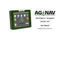
When ForeSight DXM is
first started, the Welcome
to ForeSight DXM dialog
box will open where you are
provided with options of
creating a new project or
opening an existing project
of different types.
The checkbox at the bottom
can be used to disable the
Welcome Box. ForeSight
DXM will then start with
no project initially loaded.
You can re-enable the
welcome box after it is
disabled by selecting File |
5
ForeSight DXM
Welcome Box…
Note: ForeSight DXM is optimized for 1024 x 768 and higher screen resolutions. It
will run in 800x600 resolution but you may need to turn some dialogs and tool bars
off in order to make room for the features that you actually need.
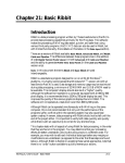
After creating a new project or opening an
existing project, the Tip of the Day dialog
will open containing a different tip each
time the program loads. Un-checking the
Show Tips on StartUp checkbox will keep
this from loading again. To access the Tip
of the Day after it has been disabled, select
Help | Tip of the Day…
Projects and the Project Navigator
The native file format used in ForeSight DXM is called a project file (*.PRO). A
project file is the only file format that can contain all of the data that ForeSight DXM
is capable of creating. The project file also stores general information about the files
that are linked to the project. For example, you can open a CAD file and merge the
data into the project file. If you need to take some of this data to the field for staking,
you can create a data collector file using some of the data in the project and link the
data collector file to the project. (See Linking, Importing, and Merging Data on Page
10.) That data collector file can then be sent to the data collector using ForeSight
DXM’s transfer utility. ForeSight DXM can also edit data collector files by
themselves – without a project, but the features and capabilities for editing these
files differ from those used with project files.
Using the project in conjunction with linked data collector files is an excellent way to
organize and manage projects. Data from multiple data collector files can be moved
into the project file and then exported to CAD or used to provide final reports and
6
Navigating the Program
results for the project. Alternatively, CAD files can be imported, edited and prepared
to move into a smaller and more easily worked-with form for use on a data collector.
All the data for a project must be stored in the same folder on your computer. (See
File Management on Page 25.) This insures that links are maintained and that the
full functionality of the project is available. Any data collector file that is linked to
the project will be moved or copied to the project folder. There is a lot of flexibility
designed into how ForeSight DXM is used so that each individual can design a
system of file management that suites their needs.
The Project Navigator
Once a project is opened you will see the Project
Navigator on the left side of the screen. The Project
Navigator can be used to select the different views and
files associated with the project. By clicking on any of the
icons in the Project Navigator you can change to
different views or edit different files.
The Tools area provides quick access to the file transfer,
file conversion and feature editing utilities.
Any files associated with the project can be selected in the
Files area of the Project Navigator.
Almost all the dialog boxes that ForeSight DXM uses will
appear over the Project Navigator. This means that you
will never have to move a dialog box to click on an object
in your drawing. You can hide the Project Navigator by
button on the Project Navigator’s title
clicking the
bar. To make it return, pull down the View menu and
click Project Navigator.
When there are no dialog boxes open, your drawing will
fill the window if the Project Navigator is turned off.
Try double clicking on each item described below.
Note: A red X
through an icon indicates that there are currently no files of that
type associated with the project. When a file is created and saved in the project
directory, the red X disappears.
7
ForeSight DXM
Plan
The Plan View is where you will do the majority of your work. It is where the map is
displayed and where most of the drawing, COGO and adjustments are done. The
Plan View displays data using northing and easting values.
Coordinates
This allows access to the Coordinate Editor.
Transfer Files
Opens the Transfer Settings dialog where the transfer settings can be configured,
followed by a Transfer dialog where file transfers between a PC and data collector
can take place.
File Conversions
Opens the File Conversions dialog box where a variety of file types can be converted
to another format.
Feature Code Editor
Opens the Feature Code Editor where a feature code file can be edited or created.
Coordinate System Editor
Opens the Coordinate System Editor where coordinate system database files can be
edited or created.
Scientific Calculator
Opens the Scientific Calculator where various calculations can be made.
TDSEdit
Opens TDSEdit, a basic word processor that can be used to generate a document
from within ForeSight DXM.
Data Files
Any data files opened while the current project is open are linked to the current
project and listed here. Part or all of the data from any of the data files can be
merged into the current project.
8
Navigating the Program
Files
Any files opened or created while the current project is open, can be viewed from this
area. You can also change views by clicking the various tabs along the bottom of the
project window.
Reports
Any report files created or opened while the current project is open are linked to the
current project and listed here.
ASCII Point Files
Any ASCII point files created while the current project is open are linked to the
current project and listed here.
Point Lists
Any report files created while the current project is open are linked to the current
project and listed here.
DC Files
Any DC files created while the current project is open are linked to the current
project and listed here.
AutoCAD Files
Any AutoCAD files created while the current project is open are linked to the current
project and listed here.
LandXML Files
Any LandXML files created while the current project is open are linked to the
current project and listed here.
Project Selection Files
Any project selection files saved while the current project is open are linked to the
current project or job and listed here.
Job Selection Files
Any job selection files saved while the current project is open are linked to the
current project or job and listed here.
9
ForeSight DXM
Creating Projects
If ForeSight DXM is started without opening an existing project, a blank project will
automatically be created where you can then link or import data from other sources.
You can also create a new project by selecting File | New Project…
Although a Project file is the only type of file that supports all the data that
ForeSight DXM is capable of creating, you are not required to initially open or work
with a ForeSight DXM project – you can also open other TDS data files in their
native format and edit them. The main difference is the type of data file that is open
limits the editing capability of ForeSight DXM and the type of data that can be saved
in the data file. (See Working With Data Files on Page 24.)
Linking, Importing, and Merging Data
When data is linked to a project, the linked data appears as if it is part of the current
project, but it is not actually stored in the project database. The link to the file is
saved so the next time you open the project, that file will still be linked and ready for
use with the project, but the data inside the linked file is not part of the project. If
the linked file is later unlinked, it is closed and all of the data it contained is not
available from the project.
You can make all or part of the data in a linked file part of the current project by
merging the data. When linked data is merged to a project, that data becomes part of
the project.
When you want to merge data from a linked file into the project, you can select to
merge all or just part of the data.
To unlink a job, expand the Jobs icon from the Project Navigator, right-click on the
job to unlink, and select Unlink From Project.
To merge linked data to the current project, select Job | Manage Data or right-click
on the linked file in the Data Files section of the Project Navigator and select
Manage Data. Select the data you want to merge from the Job view and click
[Finish].
Importing data into the current project is similar to merging data from a linked file
in that the imported data becomes part of the project. The only difference is the
imported data was not first linked to the project.
10
Navigating the Program
Linking Data Files
Data from a TDS *.JOB, *.CR5, *.RW5, or *.RAW file, as well as a Trimble *.DC and
Nikon *.Nik and *Nrd files can be linked to a project.
Select File | Link TDS Data
File…. to open the Link Data
File dialog box.
Navigate to the folder where the
desired file is stored and doubleclick on it.
Depending on the type of file
being opened, the Distance Unit
dialog box may open where you
must specify the distance units
that were used in the file being
opened.
Once the distance units are selected for a data file, they will not have to be selected
again if the same data file is re-opened later.
If the file is a raw data type, then the raw data will be reduced and points produced.
The Raw Data Regeneration Options dialog box will open first to allow changes to
the settings if necessary.
Note: Files that are linked are actually copied from their original folder into the
Project folder.
Note: DC files are not linked. Instead a job file is generated that is linked.
However, the DC file will not be displayed in the job file list but under the DC file
list.
11
ForeSight DXM
Import Control Points
Job | Import Control Points
Control points are a set of known points that are stored in a separate file, but are
used in multiple jobs, which are in the same area. You can import control points
from another .Job, .Cr5, or .Nik file. To import a set of control points, select Import
Control Points from the Job menu. Locate and select the file from which you would
like to import the points. Click on the [Open] button. DXM uses a CONTROL layer
to specify control points. The Import Control Points function will create, if
necessary, a CONTROL layer and import the points to that layer, within the
currently active job. The point names must be unique. There is no renaming or
overwriting. A small dialog will appear asking you if you want to see a report on the
imported points. Click [Yes] to generate a report or [No] for no report.
Importing Data
You can import data from an ASCII file, an AutoCAD *.DXF file or a LandXML
*.XML file to any TDS file including projects, coordinate files, or job files. The type of
data that can be imported depends on the type of TDS data file that is currently
open.
Importing from an ASCII Text File
ASCII files containing coordinate data can be
imported into an existing project. Since the
format of the data in the ASCII file can vary,
the ASCII Import wizard is used to help
define the format. The procedure for
importing an ASCII file is as follows:
1. Select File | Import | ASCII (.TXT,
etc.)…
2. Specify how each column in the text
file is separated by selecting the
appropriate radio button and click
[Next >]
12
Navigating the Program
3. Select the order of the columns by
clicking the appropriate radio button.
You can also define each column
independently by clicking on any
column heading and selecting the
appropriate title. When the dialog
box is configured correctly, click
[Next >].
4. The final dialog gives you various options on how the data will be imported.
You can select which layer you want the new data stored to from the Place
Imported Points on layer drop-down list.
Under the Point Name Option, you can select the Use point rename rules
to use the default rules for any points being imported that have duplicate
names to those in the current project. The default rename rules are specified
in the File | Preferences | Rename Rules screen, which can be quickly
accessed with the [Open Rules…] button. If Overwrite all existing points
with the same name is selected, any existing points with duplicate point
names will be overwritten with the new imported points.
If Save the imported points to a selection file is selected, a list of all the
imported points will also be written to the file specified in the corresponding
field. This file can then be used to later select the imported points via the
Selection Editor (Page 54).
13
ForeSight DXM
If the Specify Missing Elevation Threshold option is checked, a minimum
elevation must then be specified in the corresponding field. If any imported
points have elevations that fall below the elevation specified, they will be
imported as 2D points without elevations.
Check the last option, Generate and display a report after importing, if
you want to generate a report that lists the details of the import routine.
Click [Finish] to complete the ASCII import routine.
14
Navigating the Program
Importing AutoCAD DXF or LandXML XML
The procedure to import data into an existing project using an AutoCAD *.DXF file
or a LandXML *.XML file is nearly identical.
Select File | Import, select the appropriate file type.
From the Look in field, navigate to, and select the file.
The Import dialog box will open where you define how the file is to be imported.
Select the distance units used in the DXF file in the Distance unit used in the
DXF file field. (This is not available when opening a *.XML file.)
15
ForeSight DXM
Layer Options
Selecting the On Layer radio button will import the data to the selected layer.
Selecting the On DXF file layers radio button will import the data to the same layer
names where they are stored in the source file.
In LandXML imports, Group names of <CgPoints>, <Alignments> and <Parcels> will
be considered as XML layers. If a group name is not a valid layer name (e.g., it is
empty or contains invalid characters), the active layer will be used as the XML layer
of the objects in that group.
Point Name Options
ForeSight DXM uses a set of rules to determine how to name points. The [Open
Rules…] button opens the rules for renaming. These settings are remembered and
will be the same for every project you work with on the same computer.
The [Preview Renaming Report] button activates a report that details how the new
points will be named or if there are any irresolvable conflicts.
Import Options
When the Save imported objects to a selection file check box is checked, the
objects imported will also be written to the specified *.SEL selection file, which can
be used later with the Selection Editor (Page 54) to quickly select all the items that
were imported.
When Import points and line blocks is checked, point and lines are imported. This
option is a method of transferring point names and feature codes along with DXF
points and lines.
In LandXML imports, <Alignment> will be imported as point-based polylines if an
imported point can be found at the location of each of its nodes or the node refers to a
valid point, and it has no <Spiral> and <IrregularLine>, otherwise it will be imported
as an alignment. Point-based polylines will have no vertical curve segments.
In addition, an XML <Parcel> will be imported as a point-based polyline if an
imported point can be found at the location of each of its nodes or the node refers to a
valid point, otherwise, it will be imported as an alignment. <Spiral> objects used in
<Parcel> will be converted to line segments.
Import Feature Attributes is only available when Import points and line blocks
is also checked. When checked, feature attributes will also be imported. If this box,
and the box above are unchecked, all data that can be imported will be imported.
16
Navigating the Program
In LandXML, <Feature> will be imported as feature attributes if it contains TDS
feature attributes.
The Generate and display a report after importing check box is checked by
default. The report will show all the points that were imported.
Exporting Data
In the same way that data can be imported, data can also be exported from any open
TDS data file, including Projects, Coordinate files, and Job files. The data can be
exported to an ASCII text file, a Trimble DC file, an AutoCAD DXF file, or a
LandXML XML file.
The exporting procedure is the same no matter what source file you currently have
open. The only difference is you might be given options to export data that the source
file cannot contain.
The New Job routine is used to export data from the current job or project to a TDS
data file. See Exporting to a TDS Data File on Page 22 for more information on
exporting to a TDS data file.
17
ForeSight DXM
Exporting to an ASCII File
1. Select File | Export | ASCII (.TXT, etc)… This
will open the Export ASCII Coordinates dialog
box.
2. Click the
button and drag a box around the
points from the project/map view, or use the
button to open a variety of other methods to select
the items to export.
3. Select Plane Coordinates (NEZ) if you are
exporting conventional coordinates. Select
Geodetic Coordinates (LLH) if you are
exporting geodetic coordinates.
4. In the Columns section, select the checkboxes for
the types of data that you want to export and
then drag each data type in the list so that they
are listed in the order that you want them written
in the ASCII file. Each item in the resulting list
will be written to columns in the ASCII file in the
same order that they are listed here.
5. In the Column separator section, select the type
of character you want to use to separate each
column in the resulting ASCII file.
6. Click the [Export] button. A dialog box will open asking you for a file name.
Enter a name, along with the desired extension, then click [Save]. Common
extensions are .TXT and .ASC.
18
Navigating the Program
Exporting to a Trimble DC File
1. Select File | Export | Trimble (.DC)… This
will open the Export Trimble DC File dialog
box.
2. Click the
button and drag a box around the
points from the project/map view, or use the
button to open a variety of other methods to
select the items to export.
3. Click the [Export] button. A dialog box will
open asking you for a file name. Enter a name
and click [Save].
19
ForeSight DXM
Exporting to an AutoCAD DXF File
1. Select File | Export | AutoCAD (.DXF)… This
will open the Export AutoCAD dialog box.
2. Click the
button and drag a box around the
points from the project/map view, or use the
button to open a variety of other methods to select
the items to export.
3. Selecting Export point and line blocks is a method
of transferring point names, descriptions, and
feature codes along with DXF points and lines.
Not all AutoCAD applications can work with this
information.
4. Click the [Export] button. A dialog box will open
asking you for a file name. Enter a name and
click [Save].
20
Navigating the Program
Exporting to a LandXML File
1. Select File | Export | LandXML (.XML)… This will open the Export
LandXML File dialog box.
2. Select the desired objects for export by drawing a
box around them, or use the drop down arrow to
open a variety of other selection methods.
3. Select from the export options for lines and point
descriptions.
4. Click the [Export] button. A dialog box will open
asking you for a file name. Enter a name and click
[Save].
The following objects will be exported in the manner
described.
•
•
•
Points will be exported as <CgPoint>
Polylines and alignments will be exported as
<Alignment>.
• Objects will be grouped according to their layers.
<CgPoints> and <Alignments> will use layer names as their group names.
Feature attributes will be exported as <TDS_FeatureAttribute> embedded in
<Feature>
21
ForeSight DXM
Exporting Attributes
1. Select File | Export | Attributes (.DXF, .SHP
& .SHX & .DBF)... This will open the Export
Attributes dialog box.
2. Click the
button and drag a box around the
points from the project/map view, or use the
button to open a variety of other methods to
select the items to export.
3. Select the Attribute File Type.
4. Click the [Export] button. A dialog box will open
asking you for a file name if the file is in the DXF
format. If it is an ERSI Shape file, you will only
be prompted for a directory location since the
naming of Shape files is automatic. Click [Save]
to continue.
Exporting to a TDS Data File
The Export routine described above is not used to export to a TDS Data file. Instead,
you use the New Job routine to export data from the currently opened project or job
to a new TDS *.JOB or *.CR5 file, or a Nikon *.NIK file. You can also use this
routine to create a new data file with a single specified point, where no data is
exported from the current project.
The behavior of this routine will differ depending on if you are exporting from
another TDS data file such as a *.JOB or*.CR5, or a Nikon *.NIK file, or if you are
exporting from a Project file.
You can export all of the data that is compatible with the type of data file you are
exporting to from a project, or you can choose to export only some of the data. You
can also export all the data from a data file that is linked to the current project.
Once the data from a Project or linked data file is exported to a new data file, that
new file is automatically saved and linked to the current project.
22
Navigating the Program
When exporting from a data file that is open in its native format, you can export all
or part of the data in the exact same way as when exporting from a Project file, but
once the new file is created, the previous data file is closed and the new file becomes
the current data file.
1. Select File | New Job to open the New Job dialog
box.
2. In the top portion of the dialog, select if you are
exporting to a TDS Job File, TDS CR5 File, or
Nikon Data File.
3. If exporting to a CR5 file, select if you want the
points to be stored in Non-Sequential or
Sequential format (the HP48 can only work with
sequential files).
4. Select the data to export.
a. To select data from the current project or
data file, select the Selection radio button
and click the
button and drag a box
around the points from the project/map
button to open a variety
view, or use the
of other methods to select the items to
export.
b. To select data from a linked data file,
select the Linked Jobs radio button and
select the data file that you want to export
from using the corresponding drop-down
list.
5. If you do not want to export any data and simply want to create a new TDS
data file containing a single starting point, select the Start Location radio
button and specify the coordinates for the point.
6. In the Choose a name field, enter a valid name for the new file. Keep in
mind that the HP48 and all DOS-based data collectors can only work with job
names that have no more than 8 alphanumeric characters. The appropriate
3-character extension will be added automatically.
7. Click the [Create] button to create the new TDS data file.
23
ForeSight DXM
Working with Data Files
You can import, link, and merge TDS
and Nikon data files into the current
project, or you can open a TDS or Nikon
data file by itself and view and edit the
data in its native format. TDS data files
include Coordinate files (*.CR5), Job files
(*.JOB), and Raw Data files (*.RW5 and
*.RAW). Nikon data files include
coordinate files (*.NIK) and raw data
files (*.NRD). ForeSight DXM supports
both two-dimensional (2D) and threedimensional (3D) surveys.
There are some limitations that must be
considered when editing and saving a
data file.
When you open a particular data file for
the first time, you will be prompted to
specify the units used in it because this
information is not stored within the file.
If you open the same data file in the
future, you will not be prompted for this
information again since the previous
selections are saved in the Project file.
Once a data file is opened, a Job pull-down menu will be available, which contains
routines that are specific to the type of file opened.
When working with a CR5 file in its native format, layers and polylines can be
created and edited using ForeSight DXM, but this information cannot be saved to the
file since a CR5 does not support this type of data. If polylines are added, they can be
saved by themselves to a PL5 file using the CR5 | Write PL5 from Polyline
routine.
24
Navigating the Program
File Management
When ForeSight DXM opens, one of two things will happen depending on your
settings. First the Welcome dialog box will open giving the option of opening an
existing file, or creating a new project.
If the Welcome dialog box option is turned off, ForeSight DXM will open directly and
create a new empty project with the name “Untitled”. To open an existing project or
TDS data file, pull down the File menu and select either Open Project or Open
Job, or select from the list of recent files opened near the bottom of the menu.
The empty, untitled project can be used for file transfer operations and file
conversions. You can also import, link, and merge data from other files. However, it
is strongly recommended that you save the project to your desired working folder
prior to linking or importing any files since linked and imported files will be moved to
the folder where the project is and the current location may not be where you would
want the files saved. ForeSight DXM will always copy linked files to the new folder
when you save while using the Untitled project or any time you use the File | Save
As command. However, the data files will also be left in your default project directory
and this may add to unnecessary file clutter on your system.
When ForeSight DXM creates a new project, a file with the extension .PRO is created
in the default project folder. The default folder will be initially set to My Documents.
You can change this default location in File | Preferences… | System | Default
Directory. Once changed, all new projects will be saved to this directory.
Data Files
If TDS coordinate, raw data, or control files, or Nikon coordinate or raw files are
linked or imported to a project; they will be copied from their source folder to the
folder where the project is located. If a file with the same name is already in the
project folder, you will be prompted if it is okay to overwrite the existing file. DXF,
ASCII, and LandXML files are all handled in the same way.
25
ForeSight DXM
File Management Tips
There are several ways that ForeSight DXM can be used to manage, view and edit
files. Whichever way you choose to use ForeSight DXM, it is important that you
understand what the program is doing with your data files.
Single Folder Option
If you like to maintain one folder with all of your field data files in it, then you may
consider having one ForeSight DXM project file in that directory. As you add files to
the directory, also link them to that ForeSight DXM project. ForeSight DXM can
then be used to easily browse and view any data file in the directory. If edits, exports
or conversions are needed, you can do them easily and quickly. For actual projects
where you need to import or link several files, it is still best to create a new folder for
the project.
Folder for Each Project Option
Another option is if you use defined folders and sub-folders for each of your jobs. In
this case, create a specific ForeSight DXM project file for each new job you are
working on. All data that is linked to or imported into the project will also be moved
to the project folder. In this way, you can maintain the original files while also using
them for your current project.
26
Manage Data
ForeSight DXM provides a number of ways to work with data files of different types.
ForeSight DXM projects can contain links to a large number of supporting files. The
Project Navigator in ForeSight DXM can be used with the current project as a tool
to view, edit and work with these files. As you add links to files, they will appear in
the Project Navigator. If you click on a file in the project navigator other than the
actual project file, the associated editor will open that file. For a file to have an
associated editor, a program must have registered that file type on your computer, or
you must have selected a program from the file manager in Windows.
When working with a project, the actual Manage Data dialog box can be found
under the Jobs menu, or the Project menu, depending on if you are viewing a Job,
CR5, Nik, or Project file. You can also right-click on a Job, CR5, or Nik file from the
Project Navigator and select Manage Data from the context menu. You cannot
access the Manage Data dialog box when working with other non-project data files
in their native format.
ForeSight DXM allows you to edit all TDS file types in their native formats including
project files (*.PRO), TDS Windows CE and CE.net data collector files or job files
(*.JOB), TDS Coordinate files (*.CR5), and Raw Data files (*.RW5, *.RAW). In
addition, Nikon files are also supported. In all cases, the editing capabilities will be
limited compared to working with a Project file since all other data file types are not
capable of storing all the types of data that a project file can contain. All non-TDS or
Nikon files must be either imported into a Project file or converted to a job file and
linked to a project.
There are two meanings of “Project” depending on context. The first meaning is the
overall ForeSight DXM Project. This refers to the working environment of ForeSight
DXM and all the internal data and linked files. The second meaning is the actual
ForeSight DXM project database file, the (*.PRO) file. The project file contains all the
imported or created data that displays in the Plan view and it contains all the links
to the other files. In this way the ForeSight DXM project can be used to manage your
overall work.
JOB files and CR5 files are TDS data collector files. These files are used on TDS data
collectors to store field data. Although there can be multiple TDS data collector files
linked to a Project, only one can be open for editing at any given time. If you make
changes to a linked data collector file, ForeSight DXM will prompt you to save the
changes before closing the file. The current data collector file that is open in the
editor will be closed if a different file is selected from the project manager, or if the
Project is closed. If you have made changes to a job file, and then decide that these
27
ForeSight DXM
changes were incorrect, close the job file and select Cancel when prompted to save
the changes. The changes will then be discarded.
What Manage Data Does
Manage Data is used to move survey data from a project file to a data collector file, or
from a data collector file to a project file. Manage Data is the only way to accomplish
this task. The reason for this workflow is that the Manage Data feature contains the
ability to rectify differences in coordinate systems, projections, units, and also
manages point name conflicts. The Manage Data feature provides a controlled
method for transferring data to different files.
The Manage Data routine is only available when working with a Project file or when
editing a TDS or Nikon data file while it is linked to a Project file. The Manage Data
routine is not available when you are editing a data file by itself in its native format.
If you have data sets with no geodetic information, Manage Data is a simple onedialog box process. If you have geodetic data, Manage Data gives you the ability to
manage how the Projection settings interact between files and insures that the data
integrity is maintained.
Using Manage Data
If you are editing a Project file, the menu item is Project | Manage Data. If you are
editing a data file that is linked to a project, the menu item is Job | Manage Data.
If you are working with a linked data file and you select Manage Data, you will be
moving data from the current data file into the project file. If you are currently
working with the project file, you will move data from the project to the currently
selected data file.
The source and destination file names are always shown in the top section of the
Manage Data dialog box. For this description, we will reference user interface text
with <Source> and <Destination> where you would see “Merge selected objects from”
and “Into,” respectively, depending on which document the data is coming from and
where it is going.
28
Manage Data
Managing Data with No Geodetic Records
If a data file is selected and does not contain any geodetic information or any form of
specified coordinate system or projection, then using Manage Data is just a couple of
quick steps.
Open the Manage Data dialog box by selecting Job | Manage. If you are currently
working in the Project, select Project | Manage Data. Confirm that the <Source>
and <Destination> files displayed in the Manage Data dialog box are showing the
correct file names.
Select the items that you wish to move. Selection from the map view, or any of the
edit grids is allowed. You can use any of the available selection methods to select
objects. When moving data into a data file, only objects that are supported by the
data file will be moved. For example, Survey Pro Job files do not support CAD blocks;
therefore blocks are not moved into a job file.
Next, select which layer to place the objects on using the
Place merged objects section. The options involve
either selecting a particular layer to place all the objects
on, or to use the existing layer information in the source
file. ForeSight DXM will create all the necessary layers
in the destination file.
After making a layer choice, select the option for Point
Name Conflicts. You can either use the point rename
rules or select to overwrite the existing destination
points if they have the same name as points in the source
file. You can view your current point rename rules by
selecting the Open Rules button.
The manage data process will check the selected point
objects for an exact duplicate point in the destination
document. If any of the selected points already have
duplicates in the destination document, they will not be
considered by the rename rules and they will not be
merged. Points are considered duplicates only if every
parameter, including layer, is identical.
The Preview Report button allows you to see the points,
lines, and alignments that will be merged and the results
of the point renaming operations, if any. A final report
will also be available after the operation is complete.
29
ForeSight DXM
Finally, press the Merge button. The Status field will
then report the operations completed during the merge.
At this point, the Report button will open a final report
detailing all the operations of the merge. As with all
reports generated by ForeSight DXM, the report will be linked to the project if it is
saved in the project folder. The reports can provide an excellent project history
resource when reviewing the work done.
Managing Data with Geodetic Data
The Manage Data function will also transfer geodetic information between project
and job. Since the source file and destination file may have different coordinate
systems, some way of managing these differences is required.
Introduction to ForeSight DXM Geodetics
Both the job file and the project file have two main types of geodetic settings. The
first type is the projection mode and can be one of two types for the horizontal and
one of two types for the vertical.
Horizontal
Vertical
Ground – TDS Localization
Localization (+Geoid)
Mapping Plane
Ellipsoid
The mode setting is always present in the files but initially may not be set. The
default horizontal projection mode is Ground – TDS Localization and the default
vertical mode is Localization (+Geoid). If no geodetic actions have been taken with
the file, the default mode will appear or a different mode can be selected but no
projection or Localization information (i.e. projection record) will be attached.
The second type of geodetic setting is the projection record. A projection record needs
to be set prior to performing any geodetic calculations. The projection record contains
a complete set of coordinate system parameters (ellipsoid, datum, map projection,
geoid model and a possible Localization adjustment). The record can be selected from
the database when in Mapping Plane mode, configured and created in Survey Pro
while using the Ground- TDS Localization mode, or can be manually keyed in.
A project or job file can have two projection records, one in Ground – TDS
Localization mode and one in Mapping Plane mode. If a file has two projection
records, you can pick the desired record by simply choosing which horizontal
30
Manage Data
projection mode to use. Then, the projection record currently attached to the set
projection mode is the one used for geodetic computations.
Note: Please see Geodetics on Page 137 for further information on geodetic
operations in ForeSight DXM.
Note: The following examples show how to move data from a job to the project. The
procedure is the same if you were moving data from the project to a job. The terms
source and destination file are used to generalize the procedures.
Situation 1: Source file and destination file have matching
coordinate systems
In this case, operation of the Manage Data routine is exactly like the operation for
no geodetic records above. Since the records match, there is no need for any
adjustments.
Situation 2: Source file has coordinate system, destination file
does not
The first step is virtually the same as described above for no geodetic data. The only
difference is that you will see a [Next>] button instead of a [Merge] button. Once the
items are selected press the [Next>] button.
The second page of the Manage Data routine is used to rectify projection and adjust
points. The [Current Projection Details] button can be used to open a display for
complete details on the current projection set for the source file.
The Rectify Projection section has two options, Update <Destination> with
<Source> Projection or Keep <Destination> Projection. The options below in the
Adjust Points section will change based on the setting in the Rectify Projection
section. If the destination file has no projection assigned, it will default to Ground –
TDS Localization for horizontal mode and Localization (+Geoid) for vertical mode,
and no geodetic projection record data will appear in the details view.
Select the option for the projection that you want and then select the option you want
for adjusting points in the Adjust Points section. Since there is no projection yet in
the destination document, you can not adjust all points to the new system. Therefore,
31
ForeSight DXM
the Adjust only points with geodetic coordinates control is default on, and can
not be changed.
Once you are satisfied with your selections, you can preview a report using the
[Preview Report] button, or you can select [Merge] to complete the operation. A
report will be available for printing or saving when the Manage Data process
completes.
Situation 3: Source and destination file have projection records
that do not match
The first step is virtually the same as described above for no geodetic data. The only
difference is that you will see a [Next>] button instead of a [Merge] button. Once the
items are selected press the [Next>] button.
The second page of the Manage Data routine is used to rectify projection and adjust
points. The [Current Projection Details] button can be used to open a display for
complete details on the current projection set for both the source and destination
files.
The Rectify Projection section has two options, Update <Destination> with
<Source> Projection and Keep <Destination> Projection. The options in the
Adjust Points section will change based on the setting in the Rectify Projection
section.
Select the option for the projection that you want to set in the destination document
and then select the option you want for adjusting points in the Adjust Points
section. If you choose to Adjust All Points, all points will be recomputed in the new
coordinate system. Points with geodetic coordinates will be transformed based on
their geodetic position. Points with plane only coordinates will be transformed into
temporary geodetic positions, which will be used to calculate the new plane
coordinates. If you choose to Adjust only points with geodetic coordinates,
ForeSight DXM will only re-compute the plane position of those points with geodetic
positions.
32
Manage Data
Case 1: Update <Destination> with <Source> Projection
The options will be to Adjust <Destination> points
with <Source> projection or Do not adjust any
points. If you choose to adjust points, you then need to
select which points you wish to adjust. The options are to
Adjust all points in <Destination> or to Adjust only
points with geodetic coordinates. If you choose to
Adjust All Points, all points will be recomputed in the
new coordinate system. Points with geodetic coordinates
will be transformed based on their geodetic position.
Points with plane only coordinates will be transformed
into temporary geodetic positions, which will be used to
calculate the new plane coordinate. If you choose to
Adjust only points with geodetic coordinates, then
ForeSight DXM will only re-compute the plane position of
those points with geodetic positions.
If you select Do not adjust any points, then the point
adjust options will be disabled and no adjustment will be
made. This will mean that both the Latitude, Longitude
and Height values and Northing, Easting and Elevation
values will remain unchanged for the existing project
data.
Once your selections are made, click on the [Merge]
button. The Status field will display the actions taken
and the view will switch to the <Destination> file. At
this time the final Report can be generated by pressing
the [Report] button.
Case 2: Keep <Destination> Projection
The options will be to Adjust selected points with
project projection or to not adjust any points. If you
choose to adjust points, the points that will be adjusted
are the points from the source file selection. The source
file projection itself will not be changed.
The options are to Adjust all points in selection or to
Adjust only points with geodetic coordinates. If all
33
ForeSight DXM
points are selected, then all the existing points in the selection will be adjusted to the
new projection. Points without geodetic will be resolved to temporary WGS84
Latitude, Longitude, Height using the current projection and then adjusted to the
new projection. These points will not be stored with LLH values, only the NEE
coordinates will be stored for each point.
If only geodetic is selected, then only those points with geodetic Latitude, Longitude,
Height data will be adjusted. All other points will retain their existing Northing,
Easting and Elevation values.
If Do not adjust any points is selected, then no point coordinates will be adjusted.
This will mean that the Latitude, Longitude and Height values and the Northing,
Easting and Elevation values will remain unchanged.
Once your selections are made, click on the [Merge] button. The Status field will
display the actions taken and the view will switch to the <Destination> file. At this
time, the final Report data can be generated by pressing the [Report] button.
Case 3: Localization Update
When the projection records are of the same zone, but different Localization
solutions, the Adjust Points section will default to Adjust only points with geodetic
coordinates. This occurs because in the Localization case, the local coordinates are
the fixed control, and the localization transform is used to adjust the GPS
measurements into that local system. Therefore, when only the localization has
changed, you should keep the existing plane only points, and readjust only the
coordinates from geodetic measurements taken under the old Localization solution.
Polylines and Alignments
Both polylines and alignments will also be adjusted if they are selected using the
Manage Data routine. Because of the differences between polylines and alignments,
they are handled differently by the adjustment engine. Polylines and Alignments are
discussed in more detail in the Points, Polylines and Alignments section on Page 67.
Polylines
Polylines will follow the points they are attached to. Polylines are permanently
attached to points so if the points get adjusted, the polyline segments will as well.
Therefore, the orientation of each polyline segment is adjusted when we move the
points. However, polyline curves also need to be corrected. When adjusting points
with change of coordinate system, all polyline arcs are scaled by the difference of the
average combined scale factor of the two endpoints of the curve.
34
Manage Data
Alignments
Alignments are anchored at their point of beginning (POB). When converting from
one coordinate system to another, each alignment must be scaled and rotated at the
POB. The scale is the difference in combined scale factor between the two coordinate
systems at the POB. The rotation is the difference in meridian convergence between
the two coordinate systems at the POB. This method will keep the relative
proportions of the alignment correct. If the alignment is particularly long, there could
be differences in scale as compared between where the alignment started and where
it ends. This could cause differences in computed distances between existing points
and the alignment. These differences are usually quite small.
Preferences
The File | Preferences dialog box is used to configure several different settings in
ForeSight DXM. Each screen is explained below.
Colors
The Colors card allows you to change the default colors for the objects displayed in
the Plan View. Clicking
any of the colored
buttons will open a color
map where you can
select a new color by
clicking on it.
Clicking on the [Choose
colors for me] button
will change all the colors
back to the default color
scheme.
35
ForeSight DXM
Display
The Display card is used to
configure what is displayed in
the Plan View.
The Segments Per Object
section is used to configure
the number of segments that
are used to draw the
corresponding curved objects
to the screen in the Plan
View. The more segments
used, the smoother the object
will appear, but the more
complex the Plan View will
become.
The Point Labels section is
used to select what is
displayed in relation to points. The [Choose Font] button can be used to select a
different font used in the Plan View for displaying point information.
When Display Point Descriptions is checked, point descriptions will be displayed
in the Plan View. When Display Point Elevations is checked, point elevations will
be displayed in the Plan View.
There are three settings for fonts. The first is for List Views and affects the fonts
used for the data grid views for Points, Polylines, and Alignments, etc. The second
two are used for Reports generated by ForeSight DXM. To set a font, select the
Choose Font button and select the appropriate font from the Windows Font picker.
36
Manage Data
System
The System card lets you configure more options that deal with the PC’s memory and
auto-saving.
In the Memory section, the
Undo Stack Size specifies
the number of undo
procedures that can be
performed.
When Enable Autosave is
checked, a backup of the
project will automatically be
saved after each time the
number of minutes specified
is reached. This backup will
only be restored if the
program is shut down
unexpectedly. This function
is not a replacement for the
normal File | Save Project
routine, which should still be performed manually on a regular basis.
Snap
The Snap card is used to configure the snap settings. The use of snap modes is
discussed later.
The Default snap mode
order section is used to select
which snap modes will be
used by default when no snap
mode is selected in the Snap
toolbar.
Check the boxes that
correspond with the snap
modes you want to be used
and drag them so they are
listed in the order where the
modes with most priority are
listed first.
In the Snap to Grid settings,
37
ForeSight DXM
set the spacing you want to use for a snap to grid. The units are the same as those set
for the project. When the Snap to Grid button is enabled, the cursor will snap to the
nearest intersection of this grid. The origin for this grid can be set to any coordinates
in the Horizontal and Vertical Origin fields.
The Pick box size slider is used to select the size of the pick box when the cursor is
moved over the Plan View.
User Info
The User Info card can be
used to personalize your copy
of ForeSight DXM. This
information will not be used
anywhere else in the
program.
General
The General card is used to
toggle the following
checkboxes:
•
38
Automatically
update entry fields:
this will
automatically update
any field where
information is
manually entered
after the cursor
leaves that field.
When this is
unchecked, another
Manage Data
step, such as pressing [OK], is required before the new information entered is
accepted.
•
Automatically show the ‘Messages’ toolbar: When a message can be
displayed after a specific function can be performed, it will automatically be
Toggle
displayed in the message window. When this is unchecked, the
Messages button would need to be activated for messages to be displayed.
•
Display the Zoom menu when you right-click on space: When rightclicking in the plan view, the Zoom menu will be displayed at the cursor
location. If this is unchecked, nothing will happen.
•
Always generate and save a report: This will open a report in a new
window after completing a routine in ForeSight DXM that is designed to
generate a report. If this is unchecked, no report that can be saved will be
Toggle
created, but a report will be displayed in the message area if the
Messages button is activated.
•
Always show the Welcome Dialog when Starting ForeSight DXM: The
Welcome message will be displayed when ForeSight DXM is started when
this is checked.
Rename Rules
The Rename Rules card is used to define how to handle points with duplicate names
as they are merged into another project or job.
If Always rename points is
selected, all points will be
renamed as they are merged
according to how the
remaining fields are
configured.
If Rename points only if
there is a conflict is
selected, and there is at least
one conflict, all the points will
be renamed.
Under the Rename Rules,
Start with point number
should be set to the point
number that will be assigned
to the first point that is
39
ForeSight DXM
renamed. Each consecutive point that is renamed will be given the next available
point number.
When Fill gaps first, then sequential is selected, any points will be renamed with
the first available point number, where 1 is the lowest possible point name.
If Start After is selected, you can select to start the point renaming after the
Highest point number, the Next Round 100, the Next Round 1000, or the Next
Round 10000.
When Use alpha designator is selected, points will be renamed with the number
convention defined in this screen, along with predefined alpha character(s). In the
Designator field, enter the text that you want added to each renamed point and
select if you want the text to be In Front of the original point name, or In Back of it.
When Use numeric offset is selected, any numeric point name that is renamed will
be the old name plus the numeric offset entered here.
Description Codes
The Description Codes card allows for the name and type of the current descriptor
file to be quickly viewed. The file can be selected here, but it can also be changed in
the Map Menu items. Each of those routines allows for the descriptors (and
descriptor files) to be
changed.
Use Survey Pro
Description File lets
the user designate a
description file, which is
in a .txt format, by
browsing to the location
and selecting the chosen
file.
This file uses codes
can be left unchecked if
codes are not used in the
.txt descriptor file.
Use DXM Description
or Nikon PT\Code
List File can be selected
if the desired descriptor
file is in the .Des or .Lst
format. These files can
40
Manage Data
be created using the Nikon Code List Editor.
Use code (displayed) as object description can be selected for the .Des or .Lst file.
When creating a .Des or .Lst descriptor file, there is a field for Code (displayed) and
Code (Stored). If this box is checked the code (displayed) will be written into the data
file, regardless of the code (stored).
The Toolbar
The Toolbar at the top of the screen is used for accessing frequently used tools. If the
mouse is held over a button, a small text box called a Tool Tip will appear that
indicates the function of the button. These buttons can be rearranged on the tool bar,
removed from the tool bar, or moved almost anywhere on the screen as a floating
dialog box.
You can turn off individual toolbar button sets by selecting Toolbars from the View
menu. To move button groups simply click and hold at the corner of one of the groups
and drag it to where you want it.
Standard Toolbar
The Standard toolbar contains shortcuts to functions contained within the File and
Edit menus. There are shortcuts for opening, closing and saving files as well as
printing. There are also buttons that shortcut to the undo and redo functions.
View Toolbar
The View toolbar has shortcuts that allow quick access to the various views or ways
to display data.
41
ForeSight DXM
Layers Toolbar
The Layers toolbar contains options for working with layers. The usage of the layers
tools is discussed in the Layers section.
Zoom Toolbar
The Zoom toolbar contains buttons for the various zooming, panning and selecting
tools in the View menu. The usage of the zoom tools is discussed in the Zoom
section.
Cogo Toolbar
The Cogo toolbar contains shortcuts to all the options in the Cogo menu. The usage
of the Cogo functions is discussed in the Cogo section.
Dialog Bar
The Dialog Bar is the area on the left side of the user
interface where various tool and function dialogs will be
displayed. The base level of the dialog bar is called the
Project navigator. As different tools are used, the dialogs
for those tools will be stacked on the dialog bar until they
are closed.
42
Manage Data
Messages
The Messages toolbar (also called the Message box) is displayed at the bottom of the
screen. It is an area for displaying text results of calculations. The message bar will
appear any time a function is used that can generate a text report. Dragging on the
top border can resize the Messages Toolbar. You can hide the message bar by
pressing the Toggle Messages button
or selecting Toolbars from the View menu
and un-checking Messages.
The Message box can also be set in manual mode in File | Preferences… |
General. The Automatically show the “Messages” toolbar checkbox tells
ForeSight DXM to show the Message toolbar anytime a report is generated. If the
check is cleared, the Message box will not automatically open, although the reports
will still be available if you manually open the box. We suggest you leave the
Message toolbar in automatic mode until you become familiar with what functions
generate reports that are placed in the Message box.
Overview Window
The Overview window is listed in the toolbar selection list, but
is not really a toolbar in that it can only be used as a floating
window. It is used to provide a view of the entire job in
miniature. The inner box can be made larger or smaller and it
can be moved using the mouse. Moving the inner box causes a
pan action in the Plan view and shrinking or growing the box
causes a zoom action. You can also click and drag a new
window to zoom and pan to a specific area. The Overview
window will not automatically refresh when the Plan view
changes. You must right-click in the Overview window area to
get a menu and then click on Refresh.
43
ForeSight DXM
Snap Mode Toolbar
The snap mode toolbar is used to select a snap mode. The usage of the snap modes is
discussed in the Snap section.
Map Toolbar
The Map toolbar contains shortcuts to all the options in the Map menu. The usage of
the Map functions is discussed in the Map section.
DC Settings
The DC Settings toolbar contains tools for communicating with your data collector.
There are tools for transferring information and for selecting the type of unit. The
usage of these tools is discussed in more detail in the Transfer section of this manual
starting on Page 85.
44
Manage Data
Hotkeys
ForeSight DXM has keyboard shortcuts, or hotkeys, available to perform a variety of
functions quickly.
45
ForeSight DXM
Interface Conventions
There are several conventions used consistently in ForeSight DXM.
Special Function Buttons
These buttons are used throughout the program to specialize the function of the
mouse. When these buttons are clicked, they will become active. An active button is
shown graphically with a scrolling blue and white border around it. Once the button
is active the mouse can be used to select objects from the drawing.
The Mouse Select button is used to select an object from the current view.
For example the object could be a point for computing an inverse or a set
for computing an area.
The New Layer button is always displayed near a layer selection drop
down list in a dialog box. Use this button to quickly access the New Layer
dialog box to add a layer. Once the new layer is created, it will be selected
in the adjacent layer drop down list.
Right-Mouse-Click Menus
ForeSight DXM offers a context sensitive right-mouse-click menu for all objects in
the drawing. Right-click on any object and a menu will appear that will allow you to
edit, delete, or modify the object in some way. The menu will be different for each
type of object. It can be a real time saver.
46
Manage Data
Zooming and Panning
Zooming is defined as changing the current
scale of the viewing area. In effect it increases
and decreases the relative size of the drawing
on the screen. Panning moves the drawing from side to side and up and down to
facilitate viewing the job.
Zoom controls
ForeSight DXM offers several methods for zooming, they are all quite simple, and are
designed to provide you flexibility. The notation in brackets show the alternative key
combination to activate the particular zoom. If you use a wheel mouse, the wheel can
be used for zooming in and out. Also, if the wheel is pressed down, activating a wheel
click action, you can use your mouse to pan. Panning continues until the wheel
mouse is let up.
Zoom Extents (Ctrl+A)
Zoom Extents scales the view so that all the objects that are in the project and are
viewable are contained within the viewing area. In most cases, zoom extents is a very
useful tool for fitting your entire drawing inside the viewable area of your screen. If
you have one point that is a long distance from the main drawing and you hit zoom
extents, it may look like the drawing has disappeared because the objects will be so
small. You can use the zoom previous button to go back to the zoom level you were at
before. To keep zoom extents from trying to fit objects that are so far apart into the
viewable window, you can delete the object that is so far from the rest of the drawing
if it is no longer needed. You can also move the object to a separate layer and turn
that layer’s visibility off.
Zoom Window (Ctrl+W)
Zoom Window allows you to use your mouse to define a rectangular area to zoom in
to. Once the Zoom Window button is pressed, you click once in one corner of the
rectangle and once in the opposite corner to define the area you want to zoom to.
47
ForeSight DXM
Zoom Previous (Ctrl+9)
Zoom Previous moves the zoom setting to what it was prior to your last change. Zoom
previous works off a list of previous zoom settings so you can keep toggling back
through the list for as many zooms that you have done.
Zoom Next (Ctrl+0)
Zoom Next is the same as zoom previous, but moves through the list of zoom settings
in the opposite direction.
Zoom In (Alt+ (+)) and Zoom Out (Alt + (-))
These zooms move the view in or out by a specified percentage amount. The amount
of zoom can be set by using the drop down list activated by clicking on the arrow next
to the zoom button. Each time the zoom button is pushed, the view will change by the
selected amount.
Zoom Real Time (Ctrl+Q)
Zoom Real Time uses the mouse to set the zoom level. To use it, first click on the
zoom real time button, then click and drag anywhere on the drawing area. Dragging
up causes the view to zoom in and dragging down causes the view to zoom out. Zoom
real time will redraw as you zoom in or out. For very large jobs or very slow
computers, pan real time will not provide a smooth redraw of the screen. Drag the
mouse slowly for best results in these situations.
Panning
There is only one pan button and it provides all the panning functionality. Pan
Real Time is controlled using the mouse much like zoom real time. To pan, click on
the pan button then click and drag on the drawing area. Dragging left causes the
view to shift left and so on for all the directions. Pan real time will redraw as you
move the drawing. For very large jobs or very slow computers, pan real time will not
provide a smooth redraw of the screen. Drag the mouse slowly for best results in
these situations.
48
Manage Data
Selecting Objects
You select drawing objects to tell ForeSight DXM which objects you want to edit,
report on, export, etc. If no object has been selected, then ForeSight DXM cannot
make any changes.
There are four basic methods for selecting objects. These methods are valid for any
object in the current view.
Select Button
This is the button described above and is used to select individual items with the
mouse. Once the Select button is active, objects on the screen can be selected by
clicking on them. This button can also be used to draw a rectangle to select multiple
objects by clicking and dragging.
Double Clicking
You can double click on any object on the screen or in the editors at the bottom of the
screen to open the appropriate edit dialog for that object.
Right-mouse-click
Right-clicking on an object brings up a context sensitive menu for the object.
49
ForeSight DXM
The Select by Dialog Box
This dialog can be accessed from most of the edit dialogs and from anywhere it might
be necessary to select multiple objects. The dialog box can vary slightly depending
from where it was accessed.
Open the Map | Edit Multiple Points dialog box. (Also
available from other editing dialog boxes.) Click the
button to the right of the [Select] button and click on
Select by to open the Select by dialog.
Choose a selection method. The default method is by
using a rectangular area called a Window. Anything
within the window will be selected. You can also choose
by Layer, Point list, Inside (all the points that are
within the boundaries of a polyline), Polyline (all the
points that are used to define a polyline), Elevation
(select only 2D points, or points with a specific elevation),
or by using the object’s Description (e.g., a point
description of TREE).
Once the items are selected, you can click [Replace
Current] to make the selected items the only items
selected. Clicking [Add to Current] would add the
selected items to any items that were previously selected.
Clicking [Remove from Current] will remove the items
selected from the previously selected items.
The final step is to close the Select by dialog to return to
the dialog you started from, in this case to the Edit
Multiple Points dialog. ForeSight DXM will remember
the objects you have selected and you can then edit them
all simultaneously.
50
Manage Data
Colors
ForeSight DXM allows you to select the color on layers independently.
NOTE: The X through a color indicates that the color is used as the background or
highlight color. That color can still be used on an object, but it is not recommended
since the object would then be impossible to see or appear highlighted when it was
not.
If the default layer color for lines or points is changed, all the lines or
points on that layer will change to the new color. If an object is moved
from one layer to another, its color will change based on the new
layer’s default setting.
When editing a linked Job file (TDS data collector file), no color selection for layers is
possible. Job files do not support layer colors and therefore no color setting can be
made. Objects in Job files will be drawn using the default color set in the File |
Preferences dialog box.
The Edit Menu
The Edit pull-down menu contains some simple routines that
are useful while working in almost any part of ForeSight DXM.
Each routine is briefly explained here so you can use them
throughout the rest of the manual.
51
ForeSight DXM
Editing Objects
There are several different pages of editing options: Copy, Move, Edit, Rotate and
Delete. Each option is described below.
Edit Objects
This page allows you to change the layer or description of
the selected objects. Check the boxes for the changes that
you want to make then select the appropriate change in
the same field as the checkbox. Once you are finished
filling in the dialog, click the [Apply] button.
Copy Objects
The copy objects the same distance and direction as
defined by the difference between the Copy from location
and the Copy to location. For each location, you can
either enter the coordinates by hand, or click anywhere
on your map. After each location is defined, click the
[Copy] button to copy the objects. You can continue
clicking the [Copy] button to make additional copies of
the selected items to positions progressively further away
from their starting locations. The [Point Rename
Rules] button accesses the Rename Rules preferences
where the naming of the new points is configured.
52
Manage Data
Delete Objects
The Delete Objects option allows you to select objects from your map and delete
them. Simply select the objects from your map using the
Mouse Select button then click [Delete].
Note: In many dialog boxes, you can click the
button
to the right of the Mouse Select button and select List of
Selected Objects to see a list of all the objects that are
currently selected.
Rename Points
This option will rename the selected points. The [Open Rules] button accesses the
Rename Rules preferences where the naming of the new points is configured. The
[Preview Report] button displays a report so you can
preview exactly how the selected points will be renamed.
Pressing [Rename] will perform the renaming of the
selected points.
53
ForeSight DXM
2D to 3D Points
This option will assign a specified elevation to all the
selected points that do not have elevation, which will
occur after importing 2D file from AutoCAD. This
routine can also change the existing elevations of the
selected points to a specified elevation. The specified
elevation is entered in the Elevation field. When the
Only change points with missing elevations checkbox
is checked, only the selected points with missing
elevations will be changed. When this is un-checked, all
selected points will be changed.
Clear Current Selection
This option will deselect any objects that are currently selected on
your map. If you are unsure whether anything is selected in the first place just look
at the bottom right corner of the ForeSight DXM window. There will be a small,
boxed area on the status bar. If anything is selected there will be a number in the
box.
Selection Editor
The selection editor allows you to maintain up to 6 different and independent groups
of selected objects. The current selection is located on the right side of the dialog and
can be saved to any location on the left side. Save the current selection by tapping
the box where you want to save it on the left side and then tap the [Copy to The
Selection Highlighted] button. Alternatively, you can drag the Current Selection
box over any of the six boxes on the left side to save the selection. Right-clicking on
any of the saved selections provides access to useful functions including the ability to
name a saved selection. To make a saved selection the current selection, click on it,
then click the [Copy to Current Selection] button, or just drag it over the Current
Selection box on the right.
54
Manage Data
The
button will open the following list of options:
Select by: Opens the Select by dialog where objects can
be selected using several different methods. (See Page
50.)
Select all: Selects every object in the project.
Clear Selection: un-selects the currently selected
objects.
Invert Selection: un-selects the currently selected
objects and selects all the objects that are not currently
selected.
List of Selected Objects: opens a detailed list of all the
currently selected objects.
Tip: Holding the mouse cursor over the Mouse Pick button
simplified list of the selected objects.
will display a
Save Selection to File: prompts you for a file name and saves the current selection
to the specified *.SEL file, which can then be used later.
Load Selection from File: loads a selection that was previously saved to a *.SEL
file and makes it the current selection.
55
ForeSight DXM
Save Selection to File
This option is a shortcut to saving the current selection to a specific location in the
Selection Editor (described above). Simply expand the menu item by touching the
mouse to it and enter the file name. You can also use the keyboard shortcut to save
the current selection to any of the six locations by pressing [Alt] along with [F1]
through [F6], respectively.
Load Selection from
This option is a shortcut to restore a saved selection from the Selection Editor to
make it the current selection. Simply expand the menu item by touching the mouse
to it and click the saved selection from the list that you want to use as the current
selection. You can also use the keyboard shortcut to restore a specific saved selection
to use as the current selection by pressing [Alt] along with [1] through [6],
respectively.
56
Layers
Overview
A layer can be thought of as a transparent sheet of paper with objects drawn on it.
Every object drawn by ForeSight DXM is placed on a layer. Understanding layers is
important in getting the most out of ForeSight DXM.
Understanding layers
Each layer in a project can contain different objects. When all the layers are viewed
simultaneously, they make up the entire drawing. The figure below shows how four
layers are used to make up the sample drawing at the top.
57
ForeSight DXM
Using the Layer Toolbar
Start by opening a project, such as the sample project Murray.pro. Look for the
Layer toolbar (shown below). If it is not visible, select View | Toolbars and check
the Layers checkbox.
Layer Management
The Layer Management dialog box allows you to change the name of a layer, select if
the layer is visible, and change the point and line colors for a layer.
Click the
Manage
Layers button. The
Layer Management
dialog box appears (You
could also select
Project | Manage
layers.)
To delete a layer, select
it from the list and click
[Delete].
You can toggle a
particular layer to be
visible or invisible by clicking on the word Yes or No in the Visible column that
corresponds with the layer you want to change.
58
Layers
You can also change the visible setting, along
with the name and colors for a layer by
clicking on the desired layer and then clicking
the [Edit] button.
Press the [OK] button to proceed.
Editing multiple layers at once
Multiple layers can be edited simultaneously.
From the Layer Management dialog, hold
down the [Ctrl] key while clicking on each
layer that you want to edit. Once all the
desired layers are selected, click [Edit]. A
variation of the Edit Layer dialog will open
where the visibility and point/line color can be
assigned to all the selected layers.
New Layer
A new layer can be created using the following
steps.
Press the
New Layer button. This will
open the New Project Layer dialog box.
Enter a name for the new layer in the Name
field, check the box if you want the objects on
the layer to be visible, and then choose any
color you like for the points and lines by
clicking on the corresponding color buttons
and selecting a color.
Click on [OK] to continue.
59
ForeSight DXM
Active Layer
The active layer is the layer to which new objects will be added by default. It is also
the layer that the Isolate Active Layer, Point Color, and Line Color controls act
on.
The layer that is selected in the dropdown list of the Layer toolbar is the
active layer. To change the active
layer, simply select another layer from
the drop-down list.
Isolate Active Layer
When a layer is isolated, it is the only visible layer. To isolate a layer, first make
sure it is the active layer as described above and then click the
Isolate Active
Layer button.
Isolate Active Layer button will remain in the down position as long as the
The
active layer is isolated. Press the button again to show all the visible layers.
Point and Line Color
You can change the line and point colors from the Layer Management dialog box, but
a faster method is to change them directly from the Layers toolbar.
Select the layer that contains the point or line color that you want to
change from the drop-down list in the Layers toolbar. (Make this the
active layer.)
Click on the P Color button to change the color of the points on the
active layer or press the L Color button to change the color of the lines.
Select the desired color from the color map.
60
Layers
NOTE: The X through a color indicates that the color is used as the background or
highlight color. That color can still be used on an object, but it is not recommended
since the object would then be impossible to see or appear highlighted when it was
not.
Special layers
ForeSight DXM may create several special layers for you.
The Control Layer
If you have imported control points into a Job file and then moved that data into the
project, all the points from the CONTROL layer in the Job file will be placed on the
CONTROL layer. The control layer in the project simply helps organize data so you can
determine where that data came from.
In the Job file, the CONTROL layer works in much the same way. The CONTROL layer
just lets you know that the points on this layer were imported from another Job as
control.
The 0 Layer
All projects will have a Layer 0. You will not be able to delete it. ForeSight DXM
requires at least one layer so if no other layer is available, the 0 Layer becomes the
default.
The Scratch Layer
ForeSight DXM has a layer that is especially easy to erase – the SCRATCH layer.
Construction lines are placed on the SCRATCH layer for easy removal.
There are three ways to erase the scratch layer:
Menu:
View | Erase Scratch
(CTRL + E)
Keyboard:
Toolbar:
Erase scratch layer button
61
ForeSight DXM
Construction lines
When you inverse between two points, ForeSight DXM may (depending on your
settings) draw a line between them. We call this line a construction line. It is placed
on the SCRATCH layer and erased when the SCRATCH layer is erased.
You can’t directly add objects to the SCRATCH layer.
Layer tips
Experienced CAD operators tend to use more layers than beginners. Experience
shows that organizing your drawing into different layers can speed up your work.
When a dialog has an option to create a new layer, it is often a good idea to create a
new layer.
You can use the layer toolbar to find out what is on each layer of your drawing. First,
click on the
Isolate Active Layer button. Then select the first layer in the active
layer drop down list. Finally press the down arrow key. The selection in the active
layer list will move to the next layer in the list. The drawing area will show only the
objects on the new layer. Continue pressing the down arrow until you have viewed
all the layers.
62
Snap Settings
Snap is the behavior of the cursor, which allows it to “lock on” to a nearby object or
an attribute of the object. Snaps let you create points and compute exact coordinates
by clicking near the location that you are interested in. Snaps work by getting the
position information that you want from objects on the screen. For example, if you
wanted to put a new point at the intersection of two polylines then there is a snap
that will accurately place the point.
The Snap Toolbar
The Snap toolbar contains buttons that let you choose one of nine different snap
modes. The snap functions are described in the next section. Below is a diagram
showing the button for each snap mode. It is important to remember that the snap
set using the toolbar will override the default snap settings defined in File |
Preferences | Snap.
The Lock Snap button maintains your current snap mode after you have made a
selection. If the Lock Snap button is not depressed, the mode button will disable
itself after a selection, returning to the Default snap setting.
63
ForeSight DXM
Snap Modes
In general, a part of the appropriate object must pass or lie inside the pick box in
order for the snap to be effective (except when in “Snap Free” mode). The
appropriate part of the object for each mode is indicated below.
When you use the pick box to select a target for an operation, such as drawing a
polyline, ForeSight DXM will show you the location of the snap with a floating pick
box, called the Snap Indicator, drawn in your highlight color.
Pick box with
cross hairs
Snap Indication for
Snap to PI
ForeSight DXM will also show you the coordinates of the pick box position under the
lower left corner of the Plan View.
NOTE: There are several terms used to describe the mouse pointer in this manual.
Cursor is used to describe the pointer when it is held over the menu or a dialog box.
Pick box is used to describe the pointer when it is over the drawing area in any
View. The term mouse is also used as a generic term for the mouse pointer.
64
Snap Settings
Snap to
Point
The cursor will only snap to an existing
point. The point must be inside the pick
box when you click to select the point.
Snap Free
ForeSight DXM will snap to the
coordinates at the center of the pick box
when you click.
Snap to Midsegment
ForeSight DXM will snap to the middle
of the segment of a polyline or
alignment. The snap position will be on
the line.
Snap to End
of Segment
The cursor will snap to the nearest end
of a line segment. Part of the line must
pass inside the pick box when you click
to select the end of the segment
Snap to
Intersection
The cursor will snap to the intersection
of two lines when both lines are inside
the pick box.
Snap to PI
The cursor snaps to the Point of
Intersection of the arc or spiral under
the cursor. Some part of the arc or spiral
must lie inside the pick box to find the
intersection point.
Snap to
Radius
Point
The cursor snaps to the radius point of
an arc. Some part of the arc must be
inside the pick box when you click to
find the radius point.
Snap to
Nearest
The cursor snaps to the location on a
line which is the nearest to the center of
the pick box.
Snap to Grid
This setting causes the snap to lock on
to a pre-defined grid location that is
closest to the cursor. The grid is set in
File | Preferences | Snap.
See graphic on
previous page.
65
ForeSight DXM
Snap Defaults
The default snap modes can
be accessed using the File |
Preferences | Snaps. This
screen is explained on Page
37.
66
Points, Polylines and
Alignments
Overview
Points, Polylines and Alignments are all integral objects used in both ForeSight DXM
and Survey Pro. This section will discuss adding and editing these objects.
Polylines are used throughout ForeSight DXM for everything from defining
boundaries when computing areas to defining a traverse. Understanding polylines is
crucial to understanding ForeSight DXM.
Alignments are another type of line used in ForeSight DXM, but Alignments are
different from polylines in two ways. Alignments do not require any points to be
defined, whereas polylines are simple line segments between existing points.
Alignments can contain vertical curves and complex horizontal curves whereas
polylines can only contain straight lines and simple horizontal curves.
Points
Add / Edit Points
The Add / Edit Points is a dual use routine. It allows the editing of both an existing
point, or to create a new point. Add / Edit Point can only be used to edit or create
one point at a time. See the section on Edit Multiple Points for information on how to
edit multiple points.
Open the Add / Edit Points dialog by selection Map | Add Edit Points. You will
need to have points in the project or an open job file in order to edit points.
The dialog will open in Add mode. This means that there will be a new point number
in the Point field and the values for the point will be ready for editing. The routine
will switch from Add mode to Edit mode if an existing point is selected. Conversely, if
you are currently editing an existing point, and you type in a new point number or
click on the New button, the routine will switch to Add mode.
67
ForeSight DXM
Add Mode
Add mode means that the Add / Edit Points routine is ready to add a new point to the
project or the job, whichever you are currently working in. Add mode has all the
fields enabled and ready for data.
To add a point:
1. Type a new point name into the Point field, or
click on the [New] button. The [New] button
will increment the last point in the file and
place this in the field. If your last point is point
51, then 52 will be placed in the field. For
alphanumeric points, if ‘Last1’ is your last point
then ‘Last2’ will be placed in the field.
2. Enter new coordinate values. You can type
these values in, click anywhere on the map
view, or use snaps to select positions from
objects. You can also select the Elevation field
independently to select elevations from the map.
It is also possible to leave the Elevation field
blank, as 2D surveys are supported in
ForeSight DXM.
3. Enter a description in the Description field
and select the appropriate layer for the point.
4. If the point has geodetic coordinates, the
geodetic flags can be edited by clicking the
[Flags] button.
5. Once you are satisfied with the values, click on
the [Add] button. The new point will be added
to the file. The Point field will increment to the
next available point name.
You can also add geodetic coordinate values using the LLH tab on the side of the
Location section. The LLH location fields work the same as the NEZ fields, but
NEZ field values are required before storing the point. They can be set to 0 if
required.
Notice that in the button row at the bottom of the dialog box, there is a button
labeled Quick Enter. This is a way to streamline your entry of new points. You can
select which fields to automatically advance to when entering points.
68
Points, Polylines, and Alignments
Editing Geodetic Flags
When the [Flags] button is selected from the Geodetic Flags group, the Geodetic
Flags dialog appears. This dialog is used to edit the set up group and geodetic control
point flags for a single point, or for multiple points. When editing a multiple points,
you can choose to modify only the setup group, only the control point flags, or both.
When editing a single point, you will update both the setup group and the geodetic
control point flags.
Select the options you want and click OK.
Using Quick Enter
1. Click on the Quick Enter button.
2. Select your settings. For example, if you want to enter points with the same
elevation, description and layer, and want the
points to be sequential, starting at 1, then select
Northing, Easting only. Click on [OK] to save the
settings and close the dialog box. ForeSight DXM
will remember these settings.
3. Type in 1 into the Point field. Press Enter.
4. The focus will switch to the Northing field. Enter
your value and press Enter.
5. The focus will switch to the Easting field. Enter
your value. Press Enter
6. The point will be added as soon as you press Enter.
The focus will change back to the Northing field
and the point name will increment by 1.
If you do not wish to use Quick Enter, click on the [Quick Enter] button and clear
the Use quick enter field and click on [OK].
Note: When using Quick Enter, the Enter button on your keyboard will advance
through the selected fields. The Tab button will advance the focus to the next field,
just like in normal editing mode.
69
ForeSight DXM
Edit Mode
Edit Mode is enabled whenever an existing point is
selected by either clicking or typing in a point name.
Edit mode will initialize with the entry fields disabled.
To edit a particular field, you will need to click on the
check box for the section the field is in.
Editing a Point
1. Select a point to edit by selecting the point from
the map, or from the edit grid.
2. Click on the check box for the section you want
to edit.
3. Make your changes and then click [Apply]. The
changes will be saved. If you click [Close] prior
to clicking [Apply], the changes will not be
saved.
Using Geodetic
If your point has a geodetic location, LLH, as well as a
NEZ location, you can add that data using the LLH tab
in the Location section. You can add LLH information
to points even if you do not have a projection assigned,
but the program will warn you that it cannot verify the
NEZ location to the LLH location. If you wish to keep
the LLH data, select to do so, if not select to not save.
1. Select a point to edit
2. Click on the Change the location of this point
check box to activate the section.
3. Click on the LLH tab and enter your values. You
can also click on an existing GPS point to get the
values, or anywhere on the screen if you have a
projection solved.
4. Click the [Apply] button.
If you have no projection assigned, you will be warned that the program cannot verify
the NEZ location with the LLH location. Choose the option that you want from the
warning dialog box.
70
Points, Polylines, and Alignments
If you do have a projection solved, you may be warned that the plane and geodetic
positions do not match. You will be offered the option to rectify the position based off
of the current projection. If you decide to rectify the coordinates, you will be provided
with a second option. You can choose to either hold the NEZ position or the LLH
position. After making your selection the warning dialog box will close. You must
then press the [Apply] button again to make the change permanent.
Edit Multiple Points
Edit Multiple Points is very similar to Add / Edit Points. The main difference is the
ability to edit multiple points at once and the fact that you cannot add new points
from this screen.
1. Click Map | Edit Multiple Points.
2. Select the points you desire to edit. Selections can
be made from the map by clicking or dragging a
window, by using the [Select] button, by loading
from a saved selection or by clicking in the
Coordinates view window. The Coordinates view
window will show the selections made.
3. Click on the appropriate check box for the section
you wish to edit. For example, if you wish to
change the layer for all the points, click on the
Change layer check box.
4. Make the changes that you desire. You will not be
allowed to change the location of all the points to
the same place, but you can change the elevation
for all the points selected.
5. Click on the [Apply] button to save the changes.
Clicking [Close] without clicking on the [Apply]
button will close the dialog box and not save the
changes.
71
ForeSight DXM
Working with 2D Points
ForeSight DXM allows you to process data files and create projects, with two
dimensional survey data. Two-dimensional points are noted by having “---“ in the
elevation field. It is important to remember that a 2D data point can never lead to
3D data. For example, a two dimensional point, which is used to calculate an inverse
between itself and another point, can only result in a two-dimensional solution. No
elevation data will be generated.
Some other routines, which will be affected by having 2D data, include: Add/Edit
Alignments (no vertical segments will be possible), Translate and Scale (elevation
changes will only be applied to those points with a current elevation), and Cut Sheet
Reports (no cut/fill information will be generated).
Polylines
A polyline is an object that joins points together with lines
and arcs. A polyline is made up of segments that are
drawn between existing points. The figure here shows a
closed polyline. The polyline was drawn between points 5,
2, 1, 6 and 5 again to close the polyline. As you can see,
there are four segments in the polyline.
Creating Straight Polyline
Segments
Before you can create a polyline, you need some points. Open any project that
contains some points using File | Open.
You should have the point labels (View |Point Labels) turned on to make it easier
to select points.
Change the active layer to where you want the polylines stored. You can also create
Add Layer button and make the new layer the active layer.
a new layer using the
72
Points, Polylines, and Alignments
Creating Polylines by Clicking Points
There are three different ways to add straight polyline segments to a drawing. The
first one is to click on each point that you want in the polyline as described below.
1. Select Map | Add / Edit Polyline to open the
Add / Edit Polyline dialog, or simply use [Ctrl][S] the keyboard shortcut.
2. With the Line Point tab selected, click inside the
Point field so that it is active.
3. Click on the point on the map that you want to
use as the first point in the new polyline. Now as
you move the mouse, you will see an anchor line
drawn from this point to the current mouse
position. This anchor line is simulating the next
segment that will be added to the polyline.
Note: There is a shortcut for the above steps. Right-click
on the starting point and select Build Polyline… from
the context menu.
4. Click on the remaining points in the polyline. By
default, each new point will be added after the
previous point in the point list, but clicking the
Insert Before radio button will result in new
points being added before the selected point.
5. When you are finished creating the polyline, click
the bottom-left [Add] button. Once you close the Add/Edit Polyline dialog
box, the polyline will appear as a solid line on the map.
Creating a Polyline by Entering a List of Point Numbers
Another way to create a polyline is to type in a list of the points that define the
polyline.
1. From the Add/Edit Polyline dialog box, enter the first point for the polyline
in the Point field and tap the [Insert New] button located in that section.
2. Continue adding the point numbers until all the points are entered and
finally tap the [Add] button.
73
ForeSight DXM
Creating a Curved Segment
A polyline can contain a curve as long as the PC and PT
points exist in the project, along with a third point. The
third point can be either a Radius Point, the curve’s PI
Point, or another point located anywhere on the curve
segment (Pt. On Curve).
Note: Additional options for defining a curve are
available when using the Edit Curve routine, described
later.
1. With the Build tab selected in the Add/Edit
Polyline dialog box, select the Curve Points tab.
2. With the PC and PI known, select if the
remaining point of the curve is a Radius Point, a
PI Point, or a Pt. On Curve from the drop down
list.
3. Click in the PC Point field and then enter its
point number or click on the PC point in the map
view.
4. Enter the point numbers for the two remaining
points, or click on them in the map view.
5. Click the [Insert New] button. The curve will then be added to the point list
and will be displayed in the map view.
Deleting a Polyline
The easiest way to delete a polyline is to right-click on the polyline and select Delete
Polyline from the context-sensitive menu.
Editing Polylines
An existing polyline can be edited as follows.
Select Map | Add / Edit Polyline to open the Add/Edit Polyline dialog, or simply
right-click on the polyline you want to edit and select Edit Polyline from the
context-sensitive menu.
74
Points, Polylines, and Alignments
Adding to an Existing Polyline
You can add a segment to the polyline while the Build tab is selected. Simply select
the point from the list that will be a vertex to the new segment and fill in the Line
Point section or Curve Points section to define the new line or curved segment just
as you did when creating the polyline.
Editing a Straight Polyline Segment
Select the Edit tab from the Add/Edit Polyline dialog if
you want to modify or delete any existing data for the
selected polyline.
Each segment of the polyline will be listed here. Clicking
on any particular segment from the list will make that
segment stand out in the map view.
When editing a straight segment, either vertex that
defines that segment can be deleted or replaced. To
delete a vertex, click the [Delete] button that corresponds
with the vertex you want to delete. The resulting polyline
can be viewed on the map. To replace a point number for
either vertex of the selected segment, enter the new point
number in the appropriate field and press the
corresponding [Replace] button.
75
ForeSight DXM
Editing a Curved Polyline Segment
An existing curved segment can be edited or a straight segment can be turned into a
curved segment.
1. From the Add/Edit Polyline dialog box, select
the Edit tab, and then select the curved segment
from the list that you want to edit or the straight
segment that you want to change to a curved
segment
2. Select the Curve tab to access the curve editor
and check the Make Segment a Curve checkbox.
3. In the Curve Direction field, select if the curve
turns to the Left or Right (from the PC to the
PT).
4. In the Arc Type field, select if the curve is Small
(less than 180°) or Large (greater than 180°).
5. You can input the curve data in either of the
following two ways:
a. Select the Calculate using known data
radio button and select the desired length
or angle method from the drop-down list,
then define that length or angle in the
corresponding field. You can optionally
store the radius point by checking the
Store RP checkbox and entering a point
number for it in the corresponding field.
76
Points, Polylines, and Alignments
i. Length (arc length)
ii. Tangent (length from
PC to PI)
PI
PC
BC
t
en
ng 0’ Arc
a
T 10
100
Deflection
Angle (Delta)
Ta
ng
Length of Curv ent
e
ord
’ Ch
Mid-Ordinate
Long Chord
rd
ho
g. C
De
rc
g. A
De
Segment
Ra
diu
s
Sector
iv. Mid. (Mid Ordinate
length)
v. External (length)
s
diu
Ra
Fillet
iii. Delta (PC-RP-PT angle)
PT
EC
Delta
vi. Arc deg. (angle)
vii. Chord deg. (angle)
b. Select the Calculate from
Radius Point radio button and
enter the point number in the
corresponding Point field, or click within the field and then click on
the radius point from the map.
6. Click the [Apply Curve] button followed by the [Apply] button.
Note: If the straight polyline segment is still visible, click the Erase Scratch Layer
button
, or select View | Erase Scratch, or use the [Ctrl]-[E] keyboard shortcut.
Changing a Polyline’s Description
1. Click the General tab in the Add/Edit Polyline dialog.
2. Check the Change the description of the object(s) checkbox.
Changing a Polyline’s Layer
1. Click the General tab in the Add/Edit Polyline dialog.
2. Check the Change the layer of the object(s) checkbox.
3. Select the new layer for the polyline from the corresponding drop-down list,
New Layer button.
or create a new layer using the
4. Click [Apply].
77
ForeSight DXM
Alignments
Alignments typically describe the centerline of a road. An alignment can be used on
the data collector in the Offset Staking, Offset Points, Offset Lines, and Slope
Staking screens. Unlike polylines, alignments do not need points for the locations
where the alignment changes (called nodes).
Alignments are created by separately defining the horizontal and vertical details of a
line. Although no points are required to define an alignment, the starting position
must be tied to a specific location in the current job, called the POB, which can be
defined by an existing point or known coordinates.
The horizontal and vertical details of an alignment are defined in sections. The first
horizontal and vertical section always begins at the same specified starting location
and each new segment is appended to the previous horizontal or vertical segment.
Once all the horizontal and vertical alignment segments are defined, ForeSight DXM
merges the information to create a single 3-dimensional line. An existing alignment
can later be edited or deleted, but in the example below, we will create a new
alignment.
The vertical alignment (VAL) must be equal in length or greater than the horizontal
alignment. The HAL must not be greater than the VAL.
78
Points, Polylines, and Alignments
Creating an Alignment
In this step-by-step example, we will create an alignment that has all the possible
horizontal and vertical segment types.
1. Select Map | Add/Edit Alignments.
2. Click the POB tab, if it isn’t already selected and
enter a Northing, Easting and Elevation of
5000, 5000, 100, respectively. The beginning of
the alignment will then be anchored to this
location. You could alternatively check the Use
Point as POB checkbox and enter or select a
point number in the corresponding field to define
the POB using an existing point from the project.
3. Any location along the completed alignment will
be specified in stationing, beginning from the
Start Station. For simplicity, leave the Start
Station at 0+00 and click [Set POB]. This will
set the start station and automatically open the
HAL screen where you can begin defining the
horizontal portion of the alignment.
79
ForeSight DXM
Horizontal Alignment
1. We will first enter a straight line segment with
an azimuth of 0 and a length of 150. With the
HAL tab selected, make sure Line is selected for
the Segment Type. In the Azimuth field, enter
0 and in the Length field, enter 150.
2. Click either [Insert New] or [Append Segment]
to enter the first HAL segment. (If the segment is
Zoom
not visible in the Plan View, click the
Extents button.)
80
Points, Polylines, and Alignments
3. We will now add an arc to the alignment. Make
sure End is selected in the list of segments. For
the Segment Type, select Arc. For the Curve
Turn, select Right.
4. Check the Make the segment tangent to
previous checkbox so the curve will
automatically transition smoothly from the
previous segment.
5. Enter a Length of 50 and a Radius of 100 and
click either [Insert New] or [Append Segment]
to add the segment to the horizontal alignment.
Note: A new segment can be inserted before or after the
selected segment by using the [Insert New] button and
choosing either Insert Before or Insert After.
Note: When any segment is selected in the list of
segments (End must not be selected), The [Append
Segment] button changes to [Update Segment] and can
be used to make changes to the selected segment. The
selected segment is shown in the Plan View as a bold line.
81
ForeSight DXM
6. Now we will add a spiral curve to the horizontal
alignment. For the Segment Type, select Spiral
and for the Curve Turn, select Right.
7. Check the Make the segment tangent to
previous checkbox.
8. Enter a Length of 200, a Radius of 100, and
under Spiral, select CS to ST.
9. Click either [Insert New] or [Append Segment]
to enter the spiral segment to the horizontal
alignment.
We have now added all available horizontal segment
types. Next, we will define the vertical alignment.
82
Points, Polylines, and Alignments
Vertical Alignment
The horizontal and vertical alignments are defined independently, but they always
begin at the same POB.
1. Start by clicking the VAL (Vertical Alignment) tab and select the Insert
After radio button.
2. We will first enter a vertical grade of +4%.
Change the Segment Type to Line and insert a
Length of 150 and a Grade of 4.
3. Tap either [Insert New] or [Append Segment] to
add the segment to the vertical alignment.
Tip: Right-clicking within the VAL
preview window will open a
context-sensitive zoom menu that
allows a variety of zoom option for
the preview. You can also drag the
contents of the VAL preview
around with the left mouse button.
83
ForeSight DXM
4. Now we will enter a parabolic vertical curve.
Change the Segment type to Curve and enter a
Length of 250.
5. Click [Get Prev. Grade] to set the Start Grade
to 4.0 from the previous vertical segment.
6. Enter an End Grade of -2 and click [Insert New]
or [Append Segment] to add the segment to the
vertical alignment.
You have now created a new alignment using all the
available types of segments.
Note: If the horizontal and vertical alignments end at
different stations, they can only be processed in the
staking routines as far as the end of the shortest
alignment.
84
Transfer
This section will guide you through transferring to and from your TDS data collector
or Nikon total station. There are four possible modes that you can use: Microsoft
ActiveSync, Kermit Server Mode, Kermit Manual Mode, or transfers with a Nikon
Total Station, which is similar to Kermit Manual Mode. Each mode is described
below.
Note: ActiveSync mode is strongly recommended for all Windows CE-based data
collectors. It provides more user-friendly two-way communications and also allows
the use a faster USB connection for transfers. ActiveSync can be installed from the
TDS Works CD or downloaded from Microsoft.com.
The routines of Get File from Data Collector and Send Job to Data Collector
are specifically designed for use in conjunction with a ForeSight DXM project. Prior
to using these routines, it is best to have selected a name and a location for the
project and then save it. In this way, the files that are downloaded will be saved to
the proper project folder. If you are currently working in an Untitled project, it is best
to use the Send / Receive routine. Send / Receive allows the selection of a
destination folder independent of the project.
85
ForeSight DXM
Transfer Settings
1. Before performing a transfer, the transfer settings should be configured.
Select Transfer | Transfer Settings… to open the Transfer Settings
dialog box.
2. Select the type of data collector you are connecting to from the upper dropdown list. The type of data collector selected will determine which options are
available in the remaining fields.
3. In the Transfer files using: field, select the transfer mode that you want to
use from the following options. (This option is not available when
transferring with a Nikon total station.)
a. ActiveSync: This is only available on data collectors with Windowsbased operating systems, and when the ActiveSync software is
installed on the PC. This is the best choice when it is available.
b. Kermit Server Mode: This is the best option to use when ActiveSync
is not available. This option is available on most data collectors
86
Transfer
except for the HP48. The data collector must be manually set to
server mode before transfers can occur.
c.
Kermit Manual Mode: This is the only option available for the
HP48 platform.
4. Configure the Communication settings. (These are not applicable when
transferring with ActiveSync.)
a. COM Port: This is the COM Port on the PC that the data collector
cable is plugged into.
b. Baud rate: This must match the baud rate set in the data collector
for file transfers.
c.
Parity: This must match the parity set in the data collector for file
transfers. If you are unsure, select None.
5. Select the File Version that describes the type of file on your data collector.
(The options here will vary depending on the selected data collector.)
6. Checking the Always prompt for Transfer Settings checkbox will result in
the Transfer Settings dialog box to appear prior to starting any file transfer
routine.
7. Click the [OK] button.
87
ForeSight DXM
Send / Receive Files
The Transfer | Send Receive Files dialog box is used to transfer files between the
data collector or total station, and the PC. The options available will be different
depending on if you are connecting using ActiveSync, Manual Mode, or to a Nikon
total station.
Send / Receive using ActiveSync or Server
Mode
88
Transfer
When accessing the Send Receive Files dialog box using ActiveSync or Server
Mode, you not only can send and receive files; you can view the files on both systems
simultaneously. You can also create new folders and delete files or folders.
1. Connect your data collector to the PC.
a. If using ActiveSync, be sure ActiveSync detects the device and makes
a connection.
b. If using server mode, enable server mode on the data collector.
2. In ForeSight DXM, select Transfer| Send Receive Files to open the Send
Receive Files dialog box. The contents of the PC are displayed on the left
side and the contents of the data collector are displayed on the right.
3. Typically you will navigate to the folder that contains the files that you want
to transfer on the appropriate side of the dialog box, and navigate to the
folder where you want to send the files to on the other side.
4. The Files of type drop-down list can be used to display only files of the
selected type.
5. Select the file(s) that you want to transfer and click either the Copy to Data
Collector or the Copy to Local Machine button, depending on which
direction the files are being transferred.
The following buttons are available in the Send Receive Files dialog box:
•
Refreshes the directory listing.
•
Moves up one level to the parent directory (folder).
•
Will create a new folder within the current folder.
•
Deletes the selected file(s) or folder.
•
Displays only the file names in the current folder.
•
Displays the file names, size, date, and type in the current folder.
89
ForeSight DXM
Send / Receive in Manual Mode
When transferring files in Manual Mode, the files on the data collector are not visible
from the PC and only a single file can be transferred at a time. This routine also
requires interaction from both the PC and the data collector for successful transfers.
Make sure the Transfer Settings field is set to Kermit Manual Mode in the
Transfer Settings screen.
1. Connect your data collector to the PC.
2. In ForeSight DXM, select Transfer | Send Receive Files to open the Send
Receive Files dialog box. The contents of the PC are displayed.
90
Transfer
To send a file to the data collector from the PC
3. On the PC, navigate to the folder that contains the file that you want to
transfer and click once on that file to select it.
4. Click the Send to Data Collector button on the PC.
5. On the data collector, initiate the Receive File command from the transfer
menu and then click OK at the prompt on the PC to send the file.
To send a file to the PC from the data collector
3. On the data collector, choose the SEND option from the Transfer menu and
locate the file you want to send.
4. On the PC, press the Receive from Data Collector button.
5. On the data collector, send the file. (On the HP48, you would highlight the
file and press the [SELCT] softkey.)
6. Repeat these steps for any additional files that you want to send.
Send / Receive to a Nikon Total Station
When transferring files to a Nikon total station, the process behaves much like
transferring in Manual Mode since the files on the total station are not visible from
the PC and interaction from each platform is required for successful transfers.
Nikon transfers require that some details of the file being transferred be specified
since there is no way to determine this information automatically.
Some information is converted during the transfer so the resulting file can be used on
the platform where it is stored.
The Type of data collector you are connecting to field must be set to Nikon
Total Station in the Transfer Settings screen.
91
ForeSight DXM
1. Connect your total station to an available serial (COM) port on the PC.
2. In ForeSight DXM, select Transfer | Send Receive Files to open the Send
Receive Files dialog box. The contents of the PC are displayed on the left
side of the screen.
3. On the right side of the screen, go through the settings under the Units and
Distance tabs and configure them to match the details of the file you want to
send.
Note: The file details must be configured correctly or else the values in the resulting
transferred file will be incorrect.
92
Transfer
4. The File Format field is used to define the type of file that is being
transferred. The option titled Other in the File Format field is used when
you are sending a file from the total station to the PC in a non-Nikon format
(selected on the total station), such as an SDR file format.
To send a file to the total station from the PC
5. On the PC, navigate to the folder that contains the file that you want to
transfer and click once on that file to select it.
6. Click the [Send to Nikon Total Station] button on the PC.
7. Follow the directions, which appear, being sure to start receiving on the total
station prior to hitting OK on the PC.
Note: If the source file on the PC contains coordinate data as well as other types of
data, only the coordinate data will be transferred to the Nikon total station.
To send a file to the PC from the total station:
5. On the total station, select the file.
6. On the PC, press the [Receive from Nikon Total Station] button.
7. Follow the directions, which appear, being sure to press OK on the PC prior
to starting to send the file from the total station.
93
ForeSight DXM
Send Job to Data Collector
Any jobs that are linked to the current project can be easily sent to the data collector
using the Send Job to Data Collector routine. The format of the file that is sent
and how it is sent depends on the type of data collector that the file is being sent to as
well as the method the file is sent as defined in the Transfer Settings screen.
If the job is sent to a DOS-based data collector, or an HP48, it is automatically
converted to a CR5 file during the transfer. Sending to a Nikon total station is
described on Page 91.
Sending with Kermit or ActiveSync
1. Select Transfer | Send Job to Data Collector.
2. Use the Select a Job to send drop-down list to
select the job that you want to send to the data
collector. This job must be currently linked to the
project.
3. If you want the job to have a different name on
the data collector, check the Rename to checkbox
and specify the new name in the corresponding
field.
94
Transfer
1. When transferring with
ActiveSync, or in Server Mode,
the path were the job will be
sent on the data collector will
be displayed in the Remote
Path field. To change the
path, use the [Set Remote
Folder…] button to navigate
and select a new path.
2. Click [Send Job] to start the
transfer.
Note: If transferring using Manual
Mode, you will be prompted to press
the Receive button on the data
collector. After doing so, click [OK] from this dialog to send the file.
Sending to a Nikon Total Station
No matter what type of data is stored in a Job on the PC,
only the coordinates will be transferred when sending a
Job to a Nikon total station.
1. Select Transfer | Send Job to Data Collector.
2. Use the Jobs drop-down list to select the job that
you want to send to the data collector. (Only the
jobs currently linked to the project are available.)
3. Tap [Send] to continue.
Note: The file details must be configured correctly or else
the values in the resulting transferred file will be
incorrect.
4. A dialog will appear to walk you through
configuring the total station for the upload.
95
ForeSight DXM
5. On the total station, initiate the RECEIVE command and then click [OK] at
the prompt on the PC to send the file.
Get Job from Data Collector
This routine is used to transfer job files from the data collector to the local machine
and link them to the ForeSight DXM project. This routine will download selected job
files (.JOB and .CR5) plus their associated raw files (.RAW or .RW5) and any
attached support files (such as .FEA) and link these files to the project.
The first step is to transfer the data files from your data collector to the local
machine. The procedure here depends on your transfer mode. In Kermit Manual
Mode, you must transfer the files one by one before continuing. In server mode, you
can select just the jobs you want and ForeSight DXM will automatically transfer all
the associated files for you. The second step is to copy and link the transferred files
to the project directory. The final step is to review the files copied and the actions
taken in the project.
Step One: Download Files
Kermit Server or Active Sync Mode
1. With the data collector connected to the PC and
with ActiveSync running, or while it is in server
mode, select Transfer | Get Job from Data
Collector.
2. Navigate to and select the job(s) you want to
transfer to from your data collector to the PC.
3. The Files of type field can be used to display all
the *.JOB or *.CR5 files from the current
directory on the data collector.
4. With the file(s) selected, click [Transfer>] to
download the selected jobs and their associated
support files to the PC.
96
Transfer
Note: At this point, no files have been copied or linked to the project. You must
complete this wizard or no files will be saved on your PC.
The following buttons are available in the Send Receive Files dialog box:
•
Refreshes the directory listing.
•
Moves up one level to the parent directory (folder).
•
Will create a new folder within the current folder.
•
Deletes the selected file(s) or folder.
•
Displays only the file names in the current folder.
•
Displays the file names, size, date, and type in the current folder.
Manual Mode and Nikon Total Station
1. With the data collector connected to the PC select
Tools | Get Job from Data Collector.
2. Click the [Receive] button. A dialog will open
prompting you to begin the transfer from the data
collector.
3. On the data collector, issue the command to send
the file (on the HP48, you would highlight the file
and press the [SELCT] softkey) and then on the
PC, click [OK] at the prompt. For a Nikon total
station, click [OK] on the PC, and then start the
transfer from the gun.
4. Repeat the above steps to transfer any additional
files. The Files you have transferred so far
section of the Get Job from DC dialog will display
a list of all the files that have been transferred
during the current session.
5. When you are finished downloading files from the
data collector, click [Transfer>]. For each selected
job file (.JOB, .CR5, or .NIK), ForeSight DXM will
97
ForeSight DXM
attempt to pair it with the associated raw file (.RAW, .RW5, or NRD). For
jobs with no downloaded raw file, ForeSight DXM will generate a raw file
from the linked job. For any files that do not go with a selected job,
ForeSight DXM will copy them to the project directory and link them under
their appropriate file type.
Step Two: Copy Files and Link Jobs
The second step is to review the complete list of
downloaded files
In the top list box, review the complete list of files
affected by this process. This list includes both files
downloaded from the data collector that will be copied to
the project directory, and files that will be generated by
ForeSight DXM when the selected jobs are linked to the
project.
1. In the bottom list box, select the available
associated files to copy to the project directory
along with the job files. By default all associated
support files are copied with the selected jobs. It
is recommended that you select all associated
files.
2. Click [Link>] to copy the files to your project
directory and link the selected jobs to the project.
Step Three: Review Results
The final page shows a list of all the files affected by the
copy and link to the project.
1. Click [<Back] if you want to transfer more files.
2. Click [Close] when you are done.
98
Transfer
Create Job for Data Collector
This routine allows you to select a set of points from the current project and send
only the selected points to the data collector in the form of a new job and raw data
file.
1. Select Transfer| Create Job for Data
Collector to open the Send Job Wizard.
2. By default, a new job and raw data file will be
created called “Job1.” You can type a new name
for the files in the top field.
button to select the points from the
3. Use the
current project or job that you want to send to
the data collector, or use the corresponding
button to select from a variety of other pointselection methods.
4. Select what types of files you want generated.
You can choose to create a job file, raw data file
or both by selecting the appropriate check boxes.
5. You can optionally click the [Add] button to add
additional files to the Add more job data
window. You can also select any files that you do
not want to send to the data collector and remove
them from the list by clicking the [Remove
Selected] button. There are also [Select All]
and [Unselect All] buttons to highlight files in
the list.
6. When you are done with your point selection, click [Next >] to open the
second dialog.
99
ForeSight DXM
This dialog lists all the files that are to be sent to the
data collector. If connected using ActiveSync or Kermit
Server Mode, you should select the [Set Remote Folder]
button to select the path on the data collector for where
you want to send the selected files.
Click the [Send] button to start the transfer of all the
files and this will complete the procedure. If you are
connected using Kermit Manual Mode, you will be
prompted to initiate the Receive command on the data
collect prior to sending the first file. Once the data
collector is ready to receive, click [OK] from this prompt
to send the first file. Repeat this procedure until all the
files have been sent.
100
File Conversions
This section will guide you through the process of converting from one file format to
another.
The File Conversion utility is different from the File Export capabilities of the
project. File Conversion takes saved files from your system and converts them to
other file formats, which also get saved onto your system. File conversions from .JOB
to .DXF will only produce points in the DXF file. If a DXF file is required that
contains lines as well, you will need to import the Job data into a project file and then
use the File | Export routine.
Select Tools | File Conversions to open the File Conversions dialog.
101
ForeSight DXM
Select the type of source file you are converting from the Files of type drop-down
list. Only the files of the selected type will be displayed on the left side. The selection
made here will determine the file types that the source file can converted to, and
which buttons are displayed on the right side of the dialog.
In the Choose the file you want to convert section, navigate to the directory where
the file(s) you want to convert are located. Double click on any folder displayed to
change to that folder and use the following buttons to navigate.
1.
Refreshes the directory listing.
2.
Moves up one level to the parent directory (folder).
3.
Will create a new folder within the current folder.
4.
Deletes the selected file(s) or folder.
5.
Displays only the file names in the current folder.
6.
Displays the file names, size, date, and type in the current folder.
In the Destination section, leave both checkboxes unchecked if you want to save the
new file in the same location and with the same name (but with a different extension)
as the source file. Check the File Path and/or File Name checkboxes and specify a
new path or file name, respectively.
There are two ways to perform the actual conversion:
•
You can select the file(s) to be converted from the left side of the dialog; click
the button on the right side that corresponds to the file you are converting to;
then click the [Convert Selected File(s) >>] button.
•
The other method is to select the file(s) from the left side of the dialog, then
drag them over the button on the right that describes the file type you want
to convert them to.
The contents of the source file, as well as the source and destination file types
selected determine if anything other than coordinate data is written to the
destination file.
102
File Conversions
ASCII Conversion
Since there is no set standard for the format of an ASCII coordinate file, converting
to or from an ASCII file requires additional steps to define the format of the ASCII
file.
Converting from an ASCII Source File
1. Locate the ASCII source file and begin the desired conversion. The first
screen of the Convert ASCII File Wizard will open.
2. Specify how each column in the
source file are separated by
selecting the appropriate radio
button and click [Next >]
103
ForeSight DXM
3. Select the order of the columns by clicking the appropriate
radio button.
You can also define each column independently by clicking
on any column heading and selecting the appropriate title.
When the dialog box is configured correctly, click [Next >].
104
File Conversions
4. In the final screen of the
Wizard, specify the units
used for distances from the
drop-down list and click
[Finish].
Converting to an ASCII Destination File
1. Locate the desired source file and begin the ASCII conversion. The Custom
ASCII Format dialog box will open where you can define the format of the
resulting ASCII file.
2. In the Data Type field, select if you are
creating Plane coordinates or Geodetic
coordinates.
3. Select the desired order of the resulting
columns by dragging the individual column
titles listed in the order that you want them to
appear in the destination file. If you want to
exclude any particular column(s), uncheck
them.
4. In the Column separator field, define how you
want to separate each column by selecting the
appropriate radio button.
5. Click [OK] to create the ASCII file.
105
Feature Code Editor
This section covers the Feature Code Editor. A Feature File is used to help describe
objects in Survey Pro for Windows CE. Select Feature Code Editor, from the Tools
menu to launch it.
Getting Started
In the past, describing a point during data collection involved typing out a
description, or using descriptor codes prior to storing it. This was often an awkward
and limited solution.
TDS Survey Pro for Windows CE allows you to describe points using feature codes.
Feature codes can be used to describe points more quickly and in more detail than a
standard text description, particularly when data is collected for several points that
fit into a single category. For example, if the locations for all the utility poles in an
107
ForeSight DXM
area were being collected, a single feature code could be used to separately describe
the condition of each utility pole.
When describing a point using feature codes, a selection is made from any number of
main categories called features. Once a particular feature is selected, any number of
descriptions can be made from sub-categories to the selected feature called attributes.
In general, a feature describes what an object is and attributes are used to describe
the details of that object.
The primary function of the TDS Feature Code Editor is to create feature code files.
These can contain all of the feature and attribute information that is needed for any
particular job.
The TDS Feature Code Editor can also be used to view or modify the selected
features in a particular job and to export them to any of several different file formats
for use in other popular software packages.
Features
The most fundamental part of any feature code is called a feature. Features
generally describe what an object is. There are three types of features: points, lines,
and areas, which are described below.
When assigning a feature to data that was collected in Survey Pro for Windows CE,
only features of the same type are available for selection. For example, if selecting a
feature to describe a point in a job, only the point features are displayed. Likewise, if
selecting a feature to describe a polyline, only the line features in the feature file are
displayed.
Point Features
A point feature consists of a single independent point. Examples of a point feature would be
objects such as a tree, a utility pedestal, or a fire hydrant.
Line Features
A line feature consists of two or more points that define a linear object, such as a fence or a
waterline.
Area Features (Not used in Survey Pro for Windows CE)
An area feature consists of several points that define a two-dimensional object that has a
measurable area, such as a lake or a city lot.
108
Feature Code Editor
Note: Survey Pro for Windows CE does not store information that specifically defines
an area, therefore area features are ignored in Survey Pro for Windows CE. Area
features are only available to maintain compatibility with feature files used in other
TDS software applications.
Attributes
A feature, by itself, would not be useful in describing a point or a line with much
detail since a feature only helps describe what the stored point is. Attributes are
used to help describe the details of the object.
Attributes are either typed in from the keyboard or selected from a pull-down menu
and fall into the following three categories.
String Attributes
A string attribute consists of a title and a field where the user can type any characters from the
data collector’s keypad up to a specified maximum length. An example of a string attribute is
an attribute titled Notes where the user would type anything to describe a feature.
Value Attributes
A value attribute accepts only numbers from the keypad. These attributes are setup to accept
numbers that fall in a specified range. Some examples of a numeric attribute would be the
height of a tree or a utility pole’s ID number.
Menu Attributes
A menu attribute is an attribute that is selected from a pull-down menu rather than typed in
from the keypad. Menu items can also have sub-menu items. For example, you could have a
feature labeled Utility with a pull-down menu labeled Type containing Pole and Pedestal.
There could also be sub-menu items available that could be used to describe the pole or
pedestal in more detail. Menus can only be two levels deep, but there is no limit to the
number of items that can be listed in a pull-down menu.
109
ForeSight DXM
Creating a Feature File
The following examples show how each type of feature and attribute is created.
To follow along with any of the examples, you can open an existing feature file, or you
can create a new feature file using the following steps:
, or pull down the File menu and
1. Click the New Feature Code File button
select New. The New Feature File dialog box will open and prompt you for a
file name.
2. Enter a file name in the File name field. (The *.FEA extension is added for
you automatically in the next step.) The file name can be any name you want
and it does not have to match a job name.
3. Click the [Save] button.
Creating a Feature
1. The fist step to adding a new feature code can be performed using any of the
following three commands:
•
Click on the New Feature Code button
•
Press [Ctrl]-[F] on your keyboard.
•
Pull down the Features menu and select New Feature.
.
2. A question mark will be displayed along with a blinking cursor.
the name of your feature and press [Enter].
Type
4. Select if your feature will be used to describe a Point or a Line from the
drop-down list in the Type field located on the right side of the screen under
the Feature Code Properties. (Area features are not used in Survey Pro for
Windows CE.)
Note: You can easily change the name of any existing feature or attribute and is
described on Page 116.
110
Feature Code Editor
Creating a String Attribute
1. First select the desired feature that you want to associate the new attribute
with by clicking on it.
2. Open the Select Attribute Type dialog with any of the following commands:
•
Click on the New Attribute button
•
Press [Ctrl]-[A] on your keyboard.
•
Pull down the Features menu and select New Attribute.
.
3. Select the String attribute type by clicking the corresponding radio button
and then click [OK], or press [S] on your keyboard to select it.
Note: The fastest method of entering feature codes and attribute is by using the
keyboard hotkeys. For example, the fastest method to reach this point when entering
an attribute is to hold down [Ctrl] and press [A] followed by [S].
4. A question mark will be displayed along with a blinking cursor.
the name of your attribute and press [Enter].
Type
5. Define the maximum allowable length of the feature in the Max. Length
field located on the right side of the screen under the String Attribute
Properties. When the user fills in this field to describe the feature, he will
be limited to using the number of characters defined here.
Creating a Value Attribute
1. First select the desired feature that you want to associate the new attribute
with by clicking on it.
2. Open the Select Attribute Type dialog with any of the following commands:
•
Click on the New Attribute button
•
Press [Ctrl]-[A] on your keyboard.
•
Pull down the Features menu and select New Attribute.
.
111
ForeSight DXM
3. Select the Value attribute type by clicking the corresponding radio button, or
press [V] on your keyboard to select it and then click
[OK].
4. A question mark will be displayed along with a blinking cursor.
the name of your attribute and press [Enter].
Type
5. Define the parameters listed below on the right side of the screen under the
Numeric Attribute Properties.
112
•
Decimals: is the number of decimal places that will be displayed for the
entered attribute. For example, if 1 is entered here and a numeric
attribute is entered of 15.666 during data collection, the value will be
automatically rounded to 15.7.
•
Minimum: is the minimum value allowed. If an attempt is made to
enter a smaller value for this attribute during data collection, an error
will result.
•
Maximum: is the maximum value allowed. If an attempt is made to
enter a larger value for this attribute during data collection, an error will
result.
•
Default: is the default value for this attribute. If nothing is entered for
this attribute when describing the associated feature during data
collection, the default value is automatically used.
•
Units: if units have been defined using the Unit Editor, described on
Page 117, the units for this value attribute can be selected from a dropdown list. As a result when using this attribute during data collection,
the attribute title will also display the selected units in parenthesis. For
example, if a value attribute were titled Height, and Ft was selected for
the units, the title will be displayed as Height (Ft) for that attribute
during data collection.
Feature Code Editor
Creating a Menu Attribute
To illustrate how a menu attribute is created, we will build the
menu displayed here. The menu structure, as viewed from the
Feature Code Editor, is shown, along with how the dialog would
look in a data collector.
The feature code is named Utility and contains a menu attribute
named Type. The Type menu attribute contains two menu items
called Pole and Pedestal.
The Pole menu item contains three submenu items called Wood, Steel and
Composite, which would be used to describe
the type of utility pole. The Pedestal menu
item contains two sub-menu items called
Phone and Cable, which would describe the
type of utility pedestal.
Create the ‘Utility’ Feature
1. Create a new feature called Utility
with the steps described on Page 110
Add the ‘Type’ Menu Attribute
1. Select the Utility feature that was
just created by clicking on it.
2. Open the Select Attribute Type
dialog with any of the following commands:
•
Click on the New Attribute button
•
Press [Ctrl]-[A] on your keyboard.
•
Pull down the Features menu and select New Attribute.
.
3. Select the Menu attribute type by clicking the corresponding radio button, or
press [M] on your keyboard to select it and then click
[OK].
4. A question mark will be displayed along with a blinking cursor.
Type as the name of the new attribute and press [Enter].
Enter
113
ForeSight DXM
Note: You can save the work you have done at any time by clicking the Save button
or by pulling down the File menu and selecting Save.
Add the ‘Pole’ and ‘Pedestal’ Menu Items
1. Select the Type menu attribute by clicking on it.
2. Add a new menu item using any of the following commands:
•
Click on the New Menu Item button
•
Press [Ctrl]-[M] on your keyboard.
•
Pull down the Features menu and select New Menu Item.
.
3. A question mark will be displayed along with a blinking cursor.
Pole as the name of the new menu item and press [Enter].
Enter
4. Repeat Steps 1 through 3 to add the second menu item, except name it
Pedestal in Step 3.
Note: When a menu item or sub-menu item is selected, the Menu Item Properties for
that item are displayed on the right side of the screen. This contains a field called
Default where either Yes or No can be selected. When Yes is selected for a menu or
sub-menu item, a 9checkmark is displayed next to it. This indicates that this item
will be the default selection when using the feature code during data collection.
Add the Sub-Menu Items to the ‘Pole’ Menu Item
1. Select the Pole menu item by clicking on it.
2. Add a new sub-menu item using any of the following commands:
•
Click on the New Sub-Menu Item button
•
Press [Ctrl]-[S] on your keyboard.
•
Pull down the Features menu and select New Sub-Menu Item.
.
Enter
3. A question mark will be displayed along with a blinking cursor.
Wood, Steel, or Composite as the name of the new menu item and press
[Enter].
4. Repeat Steps 1 through 3 until each of the Wood, Steel, and Composite
sub-menu items have been created.
114
Feature Code Editor
Add the Sub-Menu Items to the ‘Pedestal’ Menu Item
1. Select the Pedestal menu item by clicking on it and then follow Steps 1 and
3 to create the Cable and Phone sub-menu items.
The Unit Editor
The Unit Editor is used to create a list of units, which can be used with value
attributes within the current feature file. When a value attribute is created, the
units for that attribute can be selected from the list of units created with the Unit
Editor. This will then display the
selected units in parenthesis after
the value title. For example, if a
value attribute were titled Height,
and Ft was selected for the units,
the title will be displayed as
Height (Ft) for that attribute
during data collection.
To open the Unit Editor, pull down
the View menu and select Units…
Adding a New Unit Name
To add a new unit, click the [New] button, type the new unit name, and click [Apply]
or press [Enter]. Alternatively, you can simply start typing the new unit name as
long as the Unit Editor is open.
Editing an Existing Unit Name
To change an existing unit name, simply click on it to select it then click the [Edit]
button, or double-click on the unit name. Edit the name, and press [Enter] or click
[Apply].
Deleting an Existing Unit Name
To delete an existing unit name, simply click on it to select it then click the [Delete]
button, or press the [Delete] key on your keyboard.
115
ForeSight DXM
Rearranging the Unit Names
To change the order that the unit names occur in the list, select the unit name that
or
buttons to move the unit name up or down
you want to move and press the
in the list.
Undo Changes
Clicking the [Undo Changes] button will remove all of the changes that were made
with the Unit Editor since it was last open – use cautiously!
Exiting the Unit Editor
To save your changes and close the Unit Editor, click the [OK] button. If you want to
close the Unit Editor without saving your changes, click [Cancel].
Editing a Feature File
The routines in this section are used to change the way an existing feature file looks.
Most of these routines will affect how the feature file contents will appear when
using it during data collection in Survey Pro for Windows CE, but some only affect
how things appear within the Feature Code Editor.
Renaming Items
To rename any feature or attribute, select it by clicking on it and then edit the
existing name in the Type field shown on the right side of the screen under
Properties.
Changing the Order of Items
To change the order of any feature or attribute, click on that item to select it, and
then click on the
and
keys to move the item to the desired location.
Note: Moving an item that contains sub-items will result in the selected item and all
of its sub-items to be moved simultaneously.
116
Feature Code Editor
Deleting Items
To delete an item, select the item by clicking on it and do any of the following steps:
•
Click the Delete Item button
•
Pull down the Feature menu and select Delete Item.
•
Press the [Delete] key on your keyboard.
.
Note: Deleting an item that contains sub-items will result in the selected item and
all its sub-items to be deleted.
Expanding and Collapsing Branches
Fully Collapsed
Branch
The Feature Code Editor displays feature files in a branch format
where any item that contains sub-items will show the sub-items
branch off from the main item. The items that are in view from the
Feature Code Editor depend on which branches are expanded and
which are collapsed. The branches that can be expanded are shown
with a symbol and the branches that can be collapsed are shown
with a .
To expand a particular branch, click on the
that branch. Likewise, you can click on the
particular branch.
symbol associated with
symbol to collapse a
Another way to expand or collapse a branch is right-click on the
branch and select Expand or Collapse.
Fully Expanded
Branch
You can also quickly expand all the branches in a feature file by
or by pulling the View menu
clicking the Expand All button
down and selecting Expand All. Similarly all the branches in a
or by pulling the
feature file can be collapsed by clicking the Collapse All button
View menu down and selecting Collapse All.
Moving and Copying Items
You can copy an item to another location by copying and pasting the item from the
Edit menu just like with most Windows’ applications. Likewise, you can move an
item by cutting and pasting.
Below are shortcut methods to copy or move items by dragging them with a mouse.
117
ForeSight DXM
To copy an item to another location, right-click on the item and drag it to the
new location. When using this method, the item will be displayed as the icon shown
here while the item is being dragged.
To move an item, left-click on it and drag it to the new location. When
moving an item in this way, the item is displayed as the icon shown here while it is
being dragged.
If you attempt to drag an item to an invalid location, the icon will change to a
symbol.
The Form Editor
The Form Editor is used to change the size and position of the various fields for any
particular feature. This will affect the appearance of the dialog box that is displayed
when describing a feature during data collection.
To edit a form, select the feature whose form you want to edit by clicking on it. The
form is displayed on the right side of the screen, as it would look on a data collector.
Note: The Form Editor can only be used when a feature is selected – it is not
available if an attribute is selected.
Moving a Field
To move a field in the Form Editor, position the mouse pointer over the field
that you want to move. When the pointer becomes a , click and drag the
field to the desired position.
Resizing a Field
You can resize a field horizontally or vertically with the Form Editor. To
resize horizontally, move the cursor near the desired vertical edge until the
cursor becomes a
and then click and drag the edge to the new position.
Resizing vertically is performed the same way, only the cursor is held
over the horizontal edge that needs to be moved until it becomes a .
Note: Menu items cannot be resized vertically.
118
Feature Code Editor
Changing Text Colors
To change the color of the text in any field, double click on
the text in the Form Editor. This will open the Color dialog
box. Simply click on the color that you want to use for the
text and click [OK].
If you want more colors to choose from, custom colors can be
created using the [Define Custom Colors] button.
Resetting Your Form
If a mistake is made in the Form Editor, you can use any of
the following commands to put things back the way they
were:
•
Click the [Undo Changes] button to undo all
changes that have been made since the particular
feature has been selected.
•
Click the [Reset Form] button to change everything back to the default
layout for the current feature.
•
Pull down the Features menu and select Reset All Forms… to change the
layout for every feature back to a default layout
Note: If you do not want changes to inadvertently be made to any forms, pull down
the Features menu and select Lock Form Editor. This will place a checkmark 9 next
to this menu item and disable the Form Editor. Repeat the process to unlock the
Form Editor.
Note: For information on the use of a feature file in a data collector running Survey
Pro, refer to your Survey Pro manual.
119
Nikon Code List Editor
This editor is used to create or edit Nikon Code List files in Nikon PT/Code list
format or DXM Description file format (.DES). The code list file can then be exported
to a Nikon total station for use during data collection. A code list file helps eliminate
tedious description entries in the field.
In general, a code list allows the total station user to navigate through a list of
options to find the right description for a collected point. The user has the ability to
121
ForeSight DXM
create codes, which can be embedded in lists and sub-lists. In this example, the
descriptor House is more easily found by navigating through the list Buildings |
Permanent, instead of browsing through a list of the four possible building types.
It is important to remember that each list and sub-list must culminate in a code for
the list to function properly on the total station. A list, which doesn’t end with a code
at each branch, essentially, leads the user to a dead end during data collection.
The total station can be simulated with the Demo in the lower right corner of the
screen. By pressing Alt+Space, you can navigate the descriptions and lists, just as
you would on the total station. Use this feature to insure you have created a useable
file, before you export it.
122
Coordinate Geometry
COGO is short for Coordinate Geometry – a specialized form of math that uses
functions from both trigonometry and geometry. This section will go over the COGO
routines included with ForeSight DXM.
Construction Lines
Just as a reminder, ForeSight DXM can use special lines that are drawn on the
Scratch layer to show you the operation just completed. This is helpful when doing
inverses or intersection calculations. It helps you visualize what ForeSight DXM is
using to do the calculations. Construction lines can be erased by pressing [Ctrl]-[E]
.
or by using the Erase Scratch Layer button
Inverse Point to Point
Inverse is the process of determining the distance and
direction between two locations. The basic operation of
Inverse Point to Point is very simple; it only needs two
point numbers and it will compute the distance and
direction between the points. The kind of report that is
generated depends on the Inverse Mode selected at the
top of the dialog box. The basic report is displayed in the
Results area.
To open the Inverse Point to Point dialog, select COGO
| Inverse Point to Point. There are four different
methods for performing inverses with ForeSight DXM.
See below for examples of each.
123
ForeSight DXM
Simple Mode
Select the Simple radio button in the Inverse Mode section. Then click in the Point
1: field to make it active. Click on the point that you want to inverse from. Once you
click the focus will move from the Point 1: field to the Point 2: field. Click on the
point that you want to inverse to. The results will be automatically displayed in the
Results section and in the Message Box. (You could also manually type in the point
numbers for the Point 1: and Point 2: fields and then click on the [Solve] button at
the bottom of the dialog box to get the same results.)
Once you click on the second point to fill in the Point 2: field, the focus will move
back to the Point 1: field ready for the next two points to inverse between. For as
long as you leave the Inverse dialog open, the report will continue to be added to the
text in the message box which can then be viewed, copied, printed or saved as a file.
The results of Simple mode inverses are shown below:
Side Shot Mode
Select the Side shot radio button in the Inverse Mode section. The only difference
between Side shot and Simple modes is that once Point 2: is filled in and the
results computed, the focus does not return to the Point 1: field. The focus will stay
in the Point 2: field allowing you to get a radial report of multiple points by
continuing to click on points. The results looks like below:
124
Coordinate Geometry
Sequence Mode
Select the Sequence radio button to put Inverse into the Sequence mode.
Sequence takes the previous ForeSight DXM point (Point 2: field) and makes it the
current occupy point (Point 1: field). You can think of Sequence as being similar to a
Traverse operation. The report looks like below:
Multiple Side Shot Mode
Multiple Side Shot Mode is the same as Side shot mode except you can use the
select features of ForeSight DXM to select multiple points based on description,
layer, color etc. The report looks like the following:
125
ForeSight DXM
Point in Direction
Point in Direction is possibly the most useful tool for computing new points that
ForeSight DXM offers.
From Point
Enter the point that you want to use as your base. This
is where the indicated direction and distance will
originate from for computing the new point.
Direction
Enter the direction in either bearing or azimuth. If you
have an existing line that defines the direction you can
activate this field and then click on the line to get the
direction information, or define a direction between two
points by clicking each point sequentially in the Map
View. If you want to add or subtract from the entered
direction, you can click the corresponding button and
make your desired selection.
Horizontal Distance
Enter the horizontal distance that you want to move
from the From Point to place the new point. This value
must not be zero.
+/- Angle
This field is optional and allows you to modify the angle
in the Direction field by adding to it the angle specified here. Leave this value set to
zero if you do not want to change the angle specified in the Direction field.
Elevation Change
Enter the vertical distance from the From Point’s elevation that you want applied to
the new point’s elevation. Enter positive values for an increase in elevation and
negative numbers for a decrease in elevation relative to the From Point’s elevation.
The resulting elevation is the From Point’s elevation plus the Elevation Change
value.
126
Coordinate Geometry
Results
This section displays the computed coordinates for the new point.
Store Point
If this box is left unchecked, the location of the new point will be computed after
clicking [Solve], but a new point will not be stored. If you want to store the new
point in the current job, check this box and enter a point name in the corresponding
Pt. Name field. If the point already exists, ForeSight DXM will prompt you if you
want to overwrite before removing the old point. You can also enter a description to
use for the new point. The Pt. Name field will increment by one each time you press
the [Solve] button.
Automatically advance From Point…
When this box is checked, the current Store Point will automatically become the
next From Point after clicking [Solve] in the same way as if you traversed to the
newly-created point. If left unchecked, the From Point will not change after clicking
[Solve].
Intersection
Intersection is used to determine coordinate positions of an intersection given two
existing points and either direction or distance information from the given points.
Depending on the situation, there can be up to two results. Since it is impossible to
compute the elevations of the intersections, the results will always be 2D.
Distance-Distance
Distance-Direction
Direction-Direction
127
ForeSight DXM
Line A
Enter an existing point in the Base point A field. This
will be the first reference point. Select either Direction or
Distance radio button and enter a value by clicking on an
existing object or typing it in the field.
Line B
Do the same as above for Base point B for a second
reference point.
Storing Points
By default, Store point C will be active. If you do not
want to store any points, do not check the Store point C
or Store point D check boxes. (Store point D will not be
active when performing a direction-direction
intersection.) In the case where neither store point
boxes are checked, ForeSight DXM will compute the
results and draw construction lines and print results in
the message window but no points will be stored. Once
you determine that you want to store one or both points,
check the appropriate box(es) and click on the Solve
button again.
Results
Up to two new points will be stored using the given parameters. If you did not check
the store point fields, the results will show point C and D instead of point names.
Point C is the first point stored and will be the point that is clockwise from a line
from Base Point A to Base Point B if Distance-Distance is used. If Distance-Direction
is used, point C will be clockwise from a line from the base point using distance to the
base point using direction. (See the graphic showing the types of intersections above.)
128
Coordinate Geometry
Compute Area
Area gives the area of a closed polyline. If the line is not
closed, ForeSight DXM will still give results connecting
the last vertex or point on the line to the first.
Results
Area, Perimeter, and the polyline’s Description
The units will be acres and square feet if you are using
imperial units or hectares and square meters if you are
using metric units. The perimeter will be in feet or
meters and will include the distance from the last point
or vertex to the first if it is not a closed polygon or circle
being used.
Closure Report
Closure Report gives you information on how far the last
point in a polyline is from the first point.
Results
Area (Acres and Sq ft or Hectares and Sq M), Perimeter,
Closure and a list of all the coordinate values and
stations with bearing and distance to the next point.
129
Survey Adjustments
Overview
Survey adjustments are accessed from the Adjustments menu. These adjustments
can translate, rotate, or change the scale of your project.
Translation Adjustment
When you do a translation adjustment, you are moving a group of selected objects
horizontally and/or vertically a specified distance and direction.
As an example, let's say you started a job by occupying a point whose coordinates
were unknown so you arbitrarily assigned coordinates to it. Later you learned the
actual coordinates for the initial occupy point. In this case, all of the points that were
collected that day would be incorrect by the same distance and direction, but the
points would be correct in relation to one another. Translating all of the coordinates
from the job would quickly move them to their correct positions.
131
ForeSight DXM
Translate by
The Translate by adjustment method will move a group
of selected objects by a specified distance and direction.
1. Select Adjustments | Translate / Rotate /
Scale… and be sure the Translate by tab is
selected.
2. Using the Mouse select button or the Select
button, select the objects that you want to
translate.
3. Enter the direction, distance and change in
elevation in the appropriate fields.
4. Click the [Translate] button. The selected
objects will be moved the distance and direction
that you specified.
132
Survey Adjustments
Translate to
The Translate to adjustment method will also move a selected group of objects from
one location to another location, but the distance and direction that they are moved is
defined by the current position of a base point and a final position for the base point.
All the other selected objects are moved the same distance and direction as the base
point.
1. Select Adjustments | Translate / Rotate /
Scale… and click the Translate to tab.
2. Using the Mouse select button or the Select
button, select the objects that you want to
translate.
3. Select a reference point or location. This is
typically a point with incorrect coordinates whose
coordinates are now known.
4. Select a destination point or location. This is the
position where the base point will be after the
translation.
5. Press the [Translate] button. All the selected
objects will be moved the same distance and
direction as the base point.
133
ForeSight DXM
Rotation Adjustment
When a rotation is performed to a group of objects, all the objects are rotated by a
specified amount around a reference point or location. This routine is commonly used
to adjust a survey where an assumed backsight azimuth or incorrect backsight point
was used.
1. Select Adjustments | Translate / Rotate /
Scale… and click the Rotate tab.
2. Using the Mouse select button or the Select
button, select the objects that you want to rotate.
3. In the Reference Location area of the dialog,
select either a reference point or location. After
the rotation, the coordinates for this point or
location will not change. You can think of this
point as the center of a rotating disk.
4. In the Rotation Angle area of the dialog either
enter a rotation angle in the Simple field or
specify a change in direction. The Change in
direction method calculates a rotation angle
after you enter a beginning and ending bearing
such an assumed backsight bearing and the
correct backsight bearing.
5. Click the [Rotate] button to rotate the selected
coordinates.
134
Survey Adjustments
Scale Adjustment
A scale adjustment is performed when the distances taken in the field need a scale
factor applied to them. The Scale adjustment routine can also be used to convert a
job that was collected in feet to meters, or from meters to feet (either international or
U.S. Survey feet).
Scale works on the Delta (difference) between the reference location and the object(s)
you are adjusting. If your reference northing (Y) is 5000 and the point you are scaling
has a northing (Y) of 5100 the Delta is 100 so the result would be 5000+ (100*.3048)
=5030.48, if you are converting from International feet to meters. This is also true of
elevations, the Delta of the reference elevation and the point elevation is scaled and
then added to the reference.
1. Select Adjustments | Translate / Rotate /
Scale… and click the Scale tab.
2. Using the Mouse select button or the Select
button, select the objects that you want to scale.
3. In the Reference Location section of the dialog,
enter either a reference point or reference
location. This is the point or location used that all
the other points are scaled from. After the
adjustment, the reference location will not be
changed.
4. In the Scale Factor section of the dialog enter
the scale factor that you want applied. Usually
the Northing and Easting fields will be the same.
If you do not want a scale factor applied to the
elevations, leave its scale factor set to 1. If you
are converting between feet and meters, you can
quickly get the correct scale factors by checking
the Use Conversion check box then selecting the
appropriate conversion from the drop-down list.
5. Press the Scale button to scale the selected
objects.
135
Geodetics
For projects using GPS coordinates, you must set up a coordinate system to perform
calculations on geodetic positions. ForeSight DXM uses the same coordinate systems
and geodetic calculation engine as Survey Pro. The following section describes how
to use ForeSight DXM to configure project and job file coordinate systems, how to
manage geodetic measurements, and how to use the geoid file tools to support Survey
Pro GPS data collection.
Geodetic Basics
Projection Mode
Both ForeSight DXM and Survey Pro have two horizontal and vertical projection
modes. The choice of horizontal mode depends on the project requirements. Most
survey projects are on a small site (less than 10_km or 6_mi in diameter) and use a
simple ‘flat earth’ system where plane trigonometry is applied to measured angles
and distances. For such projects the Ground – TDS Localization mode would
typically be used. In this mode, the map projection zone is configured automatically
by Survey Pro using the first GPS base setup. Other projects require that a specific
map projection is used, and distances must be scaled to the conformal map grid. For
such projects, the Mapping Plane mode is used and the map projection zone is
selected by the user from one of the records stored in the Coordinate System
Database file (*.CSD). The choice of vertical mode is simple. If you need to convert
GPS heights into orthometric elevations, you must set the vertical mode to
Localization (+Geoid). If you do not need elevations, set the vertical mode to
Ellipsoid Heights.
Below is a summary of the different horizontal and vertical projection modes:
Horizontal
Ground - TDS Localization
•
Local coordinates are at ground level, based on the project height.
•
Distances shot with EDM are at ground scale, so are 1:1 with coordinates
solved by the projection.
•
Default map projection and datum are automatically initialized with RTK
base setup in Survey Pro.
137
ForeSight DXM
Mapping Plane
•
Local coordinates are on a conformal map projection grid.
•
Distances shot with EDM are usually scaled by the combined scale factor to
distances on the map projection grid.
•
User selects map projection zone.
Vertical
Localization (+Geoid)
•
Vertical coordinate is orthometric elevation.
•
User must solve transformation from ellipsoid heights to elevations. This is
done with Localization on control points, or using a geoid model, or a
combination of both.
Ellipsoid Heights
•
Vertical coordinate is ellipsoid height.
•
This mode requires no transformation setup. Use this mode when vertical
coordinates do not need to be elevations.
Projection Records
Once the projection mode is chosen, a projection record needs to be set before geodetic
calculations can be done. A projection record is a collection of parameters to
completely define an ellipsoid, datum, map projection, geoid model, and possibly a
Localization adjustment. How you set the projection record depends on your
horizontal mode. If your horizontal projection mode is Ground – TDS
Localization, the map projection zone is configured automatically by Survey Pro.
Alternatively, you can configure this record manually by keying in the parameters. If
your horizontal projection mode is Mapping Plane, you need to select a zone from
the coordinate system database. It is possible, in both Survey Pro jobs and ForeSight
DXM jobs and projects, to have two projection records; one projection record would be
used when in Ground-TDS Localization mode and the other projection record
would be used when in Mapping Plane mode.
138
Geodetics
The default projection for new files is Ground – TDS
Localization for the horizontal projection and
Localization (+Geoid) for the vertical. The Localization
will not be initialized if no projection has been set for the
project or job file.
As with Survey Pro, ForeSight DXM also uses a
Coordinate System Database file (*.CSD) to store the map
projection and datum transformation parameters for
many different coordinate systems (zones) from around
the world. Also, horizontal and vertical localization
adjustments can be stored as site records in the database.
Below is a list of the terminology used to describe the
different records in the coordinate system database.
Zone: Is the basic record type. A zone record specifies the
type of map projection and its parameters. Most zone
records in the database already have a datum, ellipsoid,
and geoid record attached.
Site: Is a zone record with a horizontal and/or vertical
localization adjustment added. Localizations are mainly
used to correct GPS positions starting from an
autonomous base. They can be computed from control
points or from manual input of parameters.
Zone Group: Is a collection of zones and/or site records used to keep the database
organized and helps make user selection easier.
Datum: Is a type of datum transformation and its parameters. A datum record will
always have a corresponding ellipsoid record in the database.
Ellipsoid: Are the two parameters specifying the ellipsoid of the datum.
Geoid: Is the geoid model (and the associated data file) used to correct GPS heights
to orthometric elevations.
Save Record
The [Save Record] button will save the current projection record to the coordinate
system database file. Before the record is saved to the database file, the program
first searches for a matching numerical record in the database (names are ignored).
If no equivelent record is found, the program then searches the database for a record
with the same name, and will prompt the user to rename the record if required. The
139
ForeSight DXM
record is saved to the coordinate system database file, “complete.csd” in the
ForeSight DXM application directory.
Projection Settings
The Project | Projection Settings (or Job | Projection Settings) dialog is used to
configure the coordinate system for both the job and project files. The section below
describes how to select the horizontal and vertical projection mode, how to select a
map projection zone record from the database or how to configure a TDS Localization
zone, how to add a horizontal and vertical Localization adjustment to the zone, and
how to readjust the document with the new coordinate system.
140
Geodetics
Select Projection Mode
Choose the Horizontal and Vertical projection mode from
the two combo boxes at the top of the Projection Settings
dialog.
Projection Settings
The method used to select the map projection zone depends on the horizontal mode
you are working in.
Ground – TDS Localization
In Ground – TDS Localization horizontal mode, a map
projection zone is configured automatically in Survey Pro
when the first RTK base setup is performed. There is
usually no reason to configure a Localization zone using
ForeSight DXM, since the TDS Localization projection
record in the project will be set when you use Manage
Data to merge coordinates from job to project. If you do
need to set up a TDS Localization zone in ForeSight DXM,
click on the [Projection Setup] button to open the
Localization Record Setup dialog.
To configure the TDS Localization zone, you need to specify
an origin, a setup group, and a geoid (if desired). In Survey
Pro, the origin is the location of the first base position. In
ForeSight DXM, you can set the origin in one of two ways:
Click on the Pick Base Point button to select a point with
geodetic coordinates, such as a RTK survey base point. Or,
click on the Key In Base Point to input the origin values.
When keying in the origin values, you can set the Origin
Scale by entering a scale factor or by entering an origin
height, and the dialog will convert it to a scale factor. If
this localization is to match a solution from an autonomous
base, then enter the Setup Group; see the section on the
Localization Adjustment for more information on setup
141
ForeSight DXM
groups. Finally, check the Use Geoid Model box if you wish to use a geoid model
and select the appropriate model from the list. Click on [OK] when you are satisfied
with the settings.
You can also select a TDS Localization zone, or a solved TDS Localization site, from
the coordinate system database file. Click on either Pick Database Zone or Pick
Database Site to select TDS Localization records from the database. If there are no
TDS Localization zone or site records in the database you will not be able to switch to
those controls.
Map Projection
In Mapping Plane horizontal mode, a map projection
zone is selected from the coordinate system database.
Tap the [Select Zone] button to open the Map
Projection Setup dialog where you can select any zone
or site record in the database. First click on either View
Zones or View Sites to show the zones or site records in
the database file. If you wish to select a zone, select the
correct zone group and choose an available zone. If the
selected zone record does not have a datum record
attached in the database, then you must also select a
Datum from the list to attach to your zone. If the
selected zone record has a datum, its name will be
displayed. If you wish to select a site, pick the record
from the choices in the Site control. If there are no sites
in the database, then a warning message will appear
when you click on this button.
Finally, choose if you wish to use the geoid model
attached to the zone record in the database. By default, if
a record in the database uses a geoid, the Use Geoid
Model check box will be selected and the name of the
geoid will be set in the Geoid control. If you wish to use
a different geoid, then select it from the list. If you do not
wish to use a geoid, or if you wish to attach a geoid to a
record that does not have one, change the state of the Use
Geoid Model check box to reflect your choice.
142
Geodetics
Localization Adjustment
A Localization is an adjustment applied to map projection horizontal coordinates and
to ellipsoid heights to adjust the positions into any local system. A horizontal
Localization is a 2D similarity transformation used to convert the coordinates from
an intermediate map projection to coordinates in your local system. In Ground TDS Localization mode, the intermediate map projection is the default zone
initialized by Survey Pro. In Mapping Plane mode, the intermediate system is the
inaccurate map projection positions emanating from an autonomous GPS base setup.
A vertical Localization is a correction from measured ellipsoid heights or geoid
elevations calculated from heights, into local elevations. This correction can be a
simple vertical shift or a three-parameter inclined plane transformation.
To configure either the horizontal or vertical Localization, tap the [Localization]
button to open the Localization Parameter Setup dialog. The parameters to enter
for horizontal and vertical solution are the same regardless of your projection mode.
However, the parameters will have a different range of values for the two different
modes because of the different nature of the intermediate map projection. The
meaning of a site setup group, the six horizontal, and the five vertical Localization
parameters is explained in more detail below.
143
ForeSight DXM
Setup Groups
When you set up different base stations with autonomous positions, each position is
only accurate to +/- 30m (+/- 10 m with Selective Availability (SA) turned off).
Geodetic coordinates measured from your first autonomous base will not be
accurately connected to geodetic coordinates from a different autonomous base.
Although the different Localization parameters will accurately transform both sets of
data to the local coordinate system, it is not possible to
compare the geodetic coordinates from the different sets
of data.
Survey Pro and ForeSight DXM solve this problem by
assigning a setup group each time a new autonomous
base is set. A setup group is a unique flag attached to
each point record generated by GPS. Setup groups in
Survey Pro are assigned as follows:
•
When you set a new base point with an
autonomous GET, Survey Pro creates a new setup
group for this point.
•
When you collect geodetic measurements, each
new point is assigned the setup group of the
current base station.
•
When you set the base on an existing point with
geodetic coordinates, the point’s existing setup
group is used as the new base station setup
group.
•
When you set the base on a point with existing
plane coordinates and compute geodetic
coordinates using the ‘Move Base’ algorithm, the
setup group of the base point is the setup group of
the projection record.
Note: It is highly recommended that you use only one autonomous base setup in any
job or project. If you use more than one autonomous setup in a single job, both
Survey Pro and ForeSight DXM will check the setup group of each point against the
setup group of the current projection record. Both programs will only calculate using
geodetic coordinates with setup groups that match the current projection record.
144
Geodetics
Horizontal Localization Parameters
Scale: is the scale difference between the intermediate mapping plane and the local
system. Scale should generally be very close to 1.0. In Ground – TDS Localization
mode, a value of 1.0 means that GPS measured distances match the distances
between the control points on the ground at the origin reference height. In Mapping
plane mode, a value of 1.0 means that the GPS measured distances match the
distances between the control points on the conformal map grid.
Scale values are often reduced to parts per million in order to relate the factor to a
distance. One ppm (the sixth decimal place i.e. 1.000001 or 0.999999) is equal to
1mm in 1km; this is well below RTK precision. Fifteen ppm (1.000015 or 0.0.999985)
is equal to 15mm in 1km; this is a usual RTK precision, so anything in this range is
expected. A scale value significantly greater or smaller than 1.0 may indicate
problems with the control point accuracy and/or the control measurement precision.
In Ground – TDS Localization mode, it might also indicate a base reference height
too high or low for the survey area, or a scale bias in the control point local
coordinates.
Rotation: is the rotation between intermediate mapping plane and the orientation
of the local grid. In Ground – TDS Localization mode there is a wide range of
expected values for rotation, since the local grid often has a somewhat arbitrary
orientation. For example, if you solved a Localization on a traverse network started
from a magnetic compass bearing, the rotation would be a couple of degrees
(magnetic compass precision) plus the magnetic declination. In Mapping Plane
mode, the rotation should be very close to 0.0, since GPS measures orientation with
respect to geodetic north, and the intermediate mapping plane has orientation
defined by geodetic north. In Mapping Plane mode, a rotation value significantly
greater or smaller than 0.0 may indicate problems with the control point accuracy
and/or control measurement precision. It might also be an orientation bias of the
mapping plane control system that you wish to solve for.
Origin: is the point on the intermediate mapping plane about which the scale and
rotation is applied. It is the coordinate on the intermediate mapping plane of the
centroid of the control points. It is the average of the (N, E) coordinates calculated
from the control points’ geodetic locations on the intermediate mapping plane. In
Ground – TDS Localization mode, the origin should be close to (100000, 100000)m,
since these are the false north and east parameters of the localization intermediate
mapping plane. In Mapping Plane mode, this value should be in the same
neighborhood as the control point coordinates.
Translation: is the shift between the origin and the centroid of the control points’
local coordinates. In Ground – TDS Localization mode, the translation will often
be a large negative number, since the origin is around (100000, 100000) and the local
145
ForeSight DXM
coordinates are often around (5000,5000). In Mapping Plane mode, the translation
should be no larger than plus or minus 30m, since it is comes from the GPS base
autonomous setup, and this is the precision of an autonomous position.
Vertical Localization Parameters
Slope: is the North and East tilt of the inclined plane adjustment. These values are
given in parts per million, and represent the radian angle values of the deflection
between the ellipsoid normal and the local gravity vector. These values can also be
called 'deflection of the vertical'. They should typically be less than 50ppm.
Separation: is the shift between the local elevation and the vertical reference
surface. The vertical reference surface is geoid elevations when a geoid model is
used, and is the ellipsoid when ellipsoid heights are used. Three factors will affect
the expected range of values for separation: accuracy of heights, use of a geoid
model, and accuracy of local control elevations. If you have heights measured from
an autonomous GPS base, you will see +/- 30 m introduced by the autonomous
position. If you are not using a geoid model, the shift value will contain the geoid
separation. Finally, if your local elevations are not accurate, such as when you start
a job at the default (5000,5000,100), then the shift will also contain the bias between
your vertical system and real elevations.
Origin: is the local coordinate of the first point used in the control point list. The
slope values are applied from this point.
Geodetic Calculator
You can use the Tools | Geodetic Calculator function to convert positions from
one coordinate system to another. Source coordinates can come from the open
document (project, job or .CR5 file), from an ASCII text file, or keyed in one at a time.
Results can be saved in a report, or exported to an ASCII file.
146
Geodetics
Page One: Select Input Method
You can input source coordinates from one of three sources. You can Manually
input individual locations, you can L`oad ASCII data file values, or you can
Select document objects from the current file.
Choose an input method.
1. If your input method is Select document
objects, you also need to choose which coordinate
values of the selected points to use. Choose Use
plane coordinates if you wish to convert from
the document point’s plane values (North, East,
Elevation). Choose Use geodetic coordinates if
you wish to convert from the document point’s
geodetic values (Latitude, Longitude, Height). If
you choose Use plane coordinates, all selected
points will be used. If you choose Use geodetic
coordinates, only selected point records with
geodetic values will be used.
2. Tap [Next>] to select the source projection record.
147
ForeSight DXM
Page Two: Select Source Projection
The source projection is used to define the transformation from the input coordinates
to WGS84. If your input values are plane coordinates or local geodetic coordinates,
these values will be transformed to WGS84 geodetic coordinates using the source
projection.
Select the source projection type. You can choose from:
•
WGS84: will use no transformation. This
choice requires input coordinate values in
WGS84 Latitude, Longitude, Height.
•
Database zone: will display all the zone
groups and zones in the database, so you can
pick a zone. This choice allows input
coordinate values of either local geodetic or
local plane values.
•
Database site: will display all the sites in
the database so you can pick a site record.
This choice allows input coordinate values of
either local geodetic or local plane values.
•
Document projection record: will use the
document projection record for the
transformation. This choice allows input
coordinate values of either local geodetic or
local plane values.
1. Select a Zone Group and Zone if necessary. For
database zones that have no datum, the datum
control will show a list of database datums. For
database zones with a datum, database sites, and
the document projection record, the datum control will show the name of the
current datum and no selection is necessary.
2. Select Use Geoid Model as necessary. By default, the database record’s
geoid will be selected. You can over ride this to use a different goeid model or
to not use a geoid model.
3. Tap [Next>] to select the destination projection record.
Click the [Show Record Report] button to display a report of the selected record’s
projection details.
148
Geodetics
Page Three: Select Destination Projection
The destination projection is used to define the transformation from WGS84 to the
destination coordinate system.
See the instructions for selecting a source projection above.
Page Four: Specify Formats
The next page is used to specify the formats of the input and output values. The user
interface on this page will depend on your input method, and your choice of source,
and destination projection. The illustration below shows all the available controls.
1. Select the format for the source coordinates.
Choose LLH dms to enter (Latitude, Longitude,
Height) in the usual ddd.mmsssssss style. Choose
LLH deg to enter (Latitude, Longitude, Height)
in decimal degrees. Choose NEE to enter
(Northing, Easting, Elevation).
•
If your source projection is WGS84, then you
can choose only WGS84 LLH dms or WGS84
LLH deg.
•
If Select document objects was chosen in
the first screen as the input method, then this
screen is replaced with a static display of the
source format.
2.
Select the units for the source coordinates.
•
If your input type is selected document points,
then the source units are defined by the
document, and this control is replaced with a
static display of the current document units.
•
If your input type is manual, and the source
projection is the document projection, then the
units are defined by the document, and this
control is replaced with a static display of the
current document units.
3. If your input source is Load ASCII data file, then select the input file name.
Click [Browse] to open the file save dialog and pick a file name.
149
ForeSight DXM
• Check Ignore First Line (header line) if your input file has a header in
the first line. Leave this box unchecked if your input file has no header.
4. Select the format for the destination coordinates. Choose LLH dms to enter
(Latitude, Longitude, Height) in the usual ddd.mmsssssss style. Choose LLH
deg to enter (Latitude, Longitude, Height) in decimal degrees. Choose NEE
to enter (Northing, Easting, Elevation).
•
If your destination projection is WGS84, then you can choose only WGS84
LLH dms or WGS84 LLH deg.
5. Select the units for the destination coordinates.
•
150
If your input type is manual, and the destination projection is the
document projection, then the units are defined by the document, and
this control is replaced with a static display of the current document
units.
Geodetics
Page Five: Results
Manual input individual locations
If the source for input is Manual input, the final page is where you enter the
geodetic points to transform. The input values and the results for each point are
shown on the interface. The results for all points transformed in this session are also
written to the report window.
1. Input a source coordinate based on the format
specified on the previous page.
•
If your source projection is the document
projection record, and your source format is
either Local LLH dms or Local NEE, then the
ForeSight DXM graphic data exchange
mechanism is enabled for these controls, and
you can get a coordinate value by picking from
the document map.
2. Click [Convert>] to transform the source
coordinate into the destination coordinate. The
Map Plane Scale, Combined Scale, and
Convergence values are displayed for source and
destination coordinates.
3. You can also input a destination coordinate, and
hit [<Convert] to transform this value to the
source projection.
If your destination projection is the document projection
record, and your destination format is either Local LLH
dms or Local NEE, then the ForeSight DXM graphic data
exchange mechanism is enabled for these controls, and
you can get a coordinate value by picking from the
document map.
151
ForeSight DXM
Load ASCII file or Selected Document Points
If the source for input is either an ASCII file or selected
document points, the next page shows the results for each
point adjusted. You can choose the input point from the
drop down list, and the results for that point are
displayed in the user interface. The results for the entire
coordinate set are also shown in the report window.
1. Select the point name from the Point drop down
list, and the user interface will update with the
input and results for that point
Tap [Next>] to print a custom report or save the results
to an ASCII file.
152
Geodetics
Page Six: Save Custom ASCII file or Report
If the source for input is either an ASCII file or selected document points, the final
page allows you to generate and save a custom report file and/or a custom ASCII
output file.
1. If you want to store an ASCII output file, select
the desired ASCII delimiter from the drop down
list.
2. Select the fields you want in your output, and
arrange the field order. You can drag the fields
up or down to change the field order. Only fields
that are checked will be included in the output.
3. Select additional information you desire in the
output. You can include: a file header describing
the fields, the source average combined scale
factor, the destination average combined scale
factor.
4. Click [Report] to generate a ForeSight DXM
report with the selected fields.
5. Click [Save], enter a file name, and select the
[Save] button to save the selected fields to the
specified ASCII file.
153
ForeSight DXM
Import GPS Control
In some cases, you can occupy a GPS control point in the field during data collection,
but you do not have the correct mapping plane local north, east, elevation coordinate
for that control point. In this case, you cannot use this point to solve a localization.
The Import GPS Control routine automates the process of taking a data collected
point and merging it with the proper local north, east, elevation coordinate from
some external source to create a GPS control point. Once there are enough control
points, you can localize and update all of the GPS collected points with the proper
local coordinates. You can only import GPS control when your horizontal projection
mode is set to Mapping Plane. There are three common work flow scenarios when
using the Import GPS Control routine:
154
•
You start a survey with your base on a new autonomous position. You set the
base to log data for post processing while you do your RTK. In the field, you
begin your survey without solving localization. You then submit the post
processing data file to the NGS’ OPUS service and get back the calculated
local coordinate. You then wish to adjust the survey to match the calculated
coordinate for your base.
•
You start a survey with your base on a new autonomous position. You occupy
one or more NGS control monuments during the survey, but you do not have
the data sheet with the published north, east, and elevation coordinate in the
field. You get back to the office and download these data sheets from the NGS
web site, and you wish to solve a localization using these points as control.
•
You start a survey with your base on an autonomous position. You occupy one
or more control points during the survey, but you do not have the proper
north, east, elevation coordinate in the field. You get back to the office and
you calculate the proper coordinate for these points by some method such as
an adjustment of post processed baselines, or from another crew’s job file
measurement to the same point. You then wish to solve a localization using
these points as control.
Geodetics
Detailed Procedure
1. Open the Adjustments | Import GPS Control screen. The menu item is
enabled only when there is a valid projection setup for the current job/project and
when the horizontal projection mode is set to mapping
plane.
2. Select a point that you wish to make into a GPS
control point. You must select points that have
geodetic (LLH) coordinates.
3. Select a method to input the source for the accurate
location of the control point. Your choices are: NGS
Data Sheet .txt file, OPUS Solution Results .txt file, or
Key In Coordinate. The selection made here will
determine the fields that follow in the dialog box.
Note: To use an NGS data sheet, download the data
sheet for one or more desired points from the NGS web
site, open the *.htm data sheet files using your web
browser, and then click on File > Save As. Specify to save
the file as a plain text file, and make sure the file has a
.txt extension. To use an OPUS solution results file, open
the email containing the solution report with your email
editor, and then click on File > Save As. Specify to save
the file as plain text, and make sure the file has a .txt
extension.
4. Enter the source for the accurate local coordinate to apply to the selected point. If
you are using an OPUS solution report or an NGS data sheet, use the Browse
button to locate the appropriate directory and then pick the desired item from the
drop down list. If you want to see additional details on any item, tap Details . If
you are keying in a local coordinate, choose the Coordinate Type and key in the
North, East, and Elevation, or the Latitude, Longitude, and Height.
5. Tap Apply after you have entered the local coordinate for the selected point.
Repeat the above steps for any additional points if necessary.
155
ForeSight DXM
Solve Localization
When you start a GPS survey from an autonomous base position, you need to solve a
localization to adjust GPS measurements into local coordinates. This is the case for
both horizontal projection modes. In most situations, localization takes place in the
field using Survey Pro, but in situations where there was not enough control
information to localize in the field, or you simply want to redo your localization, you
can localize with ForeSight DXM using the Adjustments | Solve Localization
menu item.
When using Ground - TDS Localization, you need to solve a localization to relate your
arbitrary GPS start point into your non-geodetic local system. When using a Mapping
Plane, you need to solve a localization to shift the autonomous GPS start point into
accurate geodetic coordinates.
In either horizontal mode, the procedure is the same. Starting from an autonomous
GPS base setup, you measure GPS positions on control points with know local plane
(N,E) coordinates. The parameters for a 2D similarity transformation are calculated
with a least squares solution using the control points. These parameters are added
to the zone record (the default Ground - TDS Localization mode zone or the selected
Mapping Plane mode zone) to create a zone based site record.
Vertical localization, with or without a geoid model, uses the same field procedure.
Starting from an autonomous GPS base setup, you measure GPS positions on control
points with know local elevations. The vertical adjustment parameters are
calculated from the control points. The vertical adjustment will be either a shift to
correct geoid elevations to local elevations, or an inclined plane to correct for vertical
shift and tilts.
Localization with Control Points
Horizontal localization is a simple 2D similarity transformation that scales, rotates
and translates coordinates on an intermediate mapping plane to coordinates in your
local system. In Ground - TDS Localization mode, the intermediate mapping plane is
the default map projection initialized for ground distances at the base height. In
Mapping Plane mode, the intermediate mapping plane is the inaccurate coordinates
calculated on the selected map projection from the autonomous GPS base.
Vertical localization is a correction from measured ellipsoid heights or geoid
elevations calculated from heights, into local elevations. This correction can be a
simple shift or a three-parameter inclined plane.
156
Geodetics
Localization with Control Points: Summary
¾
Take GPS measurements to at least the minimum number of control points.
In Ground – TDS Localization mode, at least two horizontal control points are
required. In Mapping Plane mode, at least one horizontal control point is
required. In Localization (+Geoid) mode at least three vertical control points
are required when there is no geoid model, and one vertical control point is
required when there is a geoid model.
¾
Click Adjustments | Solve Localization to open the Solve Localization
dialog.
Select the points to use for horizontal and vertical control and select the
desired options in the remainder of the dialog.
¾
¾
Tap Solve to compute a localization solution.
¾
Verify the solution residual or misclosure quality and tap Apply to apply the
localization.
Detailed Procedure
Since the procedure is the same for both horizontal and vertical localization
solutions, the instructions below cover both cases.
1. Click Adjustments | Solve Localization to open the Solve Localization dialog.
157
ForeSight DXM
2. In the GPS Control Pt List, control points collected
will be identified with an H and/or V. Points marked
H will be used to solve horizontal localization. Points
marked with a V will be used to solve vertical
localization. You can select or deselect any point by
highlighting that point and then tap corresponding H
and/or V column, or you can press H and/or V on the
keyboard.
3. If you wish to hold the horizontal scale of the GPS
measurements, but you want the localization
adjustment to correct for a rotation, select Solve
Rotation Only in the Horizontal field.
Note: When using Solve Rotation Only, you are only
allowed to use two horizontal control points.
4. In the Vertical field, you have the choice to adjust
Vertical Shift Only, Vertical Shift + Inclined Plane, or no
vertical adjustment.
5. When blunder detection is enabled, we will use all of
the selected horizontal and vertical control points to
attempt to detect any gross errors in the localization
control points. If any gross errors are detected, you will be prompted to remove
those points from the horizontal or vertical solution and the localization will be
resolved with the new control point assignments. When blunder detection is
turned off, we will simply show the RMS of the solution in the results area.
Note: In order for blunder detection to run, you must have at least one more than
the minimum number of control points for the H or V solution.
6. Tap Solve. The localization parameters are computed using the selected control
points, and the dialog box is filled in with solution RMS values.
158
Geodetics
7. The Solution Results box consists of the result of the
solution along with an indicator hinting to the
quality of the solution. If blunder detection is used,
those results are displayed here, otherwise RMS
results are shown.
If you are not happy with the solution residual or
misclosure values for any point and have not yet
applied the solution, you can change the control
points used by tapping in the H and/or V columns
and then tap Solve again to recalculate the solution
and update the Solution Results.
8. When you are happy with the
solution, tap Apply. The Adjust
with Change of Projection dialog
will open where you can select to
apply the solution results to all or
none of the points and lines of the
project. Tap OK to finish the
adjustment. GPS control flags
are then updated and the project
marked modified.
159
ForeSight DXM
Adjust With Projection
You can use the Adjustments | Adjust with Projection function to convert
document objects from one coordinate system to another, or to readjust document
objects to match the current coordinate system.
Page One: Select Objects
You can perform two types of adjustment with selected document objects. The first
type of adjustment is to transform document objects from a source coordinate system
to a destination coordinate system. This is the type of adjustment done by the
Manage Data routine and the Projection Settings routine when the projection record
is changed in the document. The second type of adjustment is to update either the
geodetic or the plane coordinates of selected objects based on the current projection
record. This is the type of adjustment performed by the Survey Pro projection
“Readjust Points” routine.
1. Select objects to adjust. There are four options to
adjust selected objects:
160
•
Adjust all points. This option will adjust all
the plane location of all selected objects from
a chosen source projection to a chosen
destination projection. Points with geodetic
coordinates will be adjusted to the destination
projection using their WGS84 (Latitude,
Longitude, Height) value. Points with plane
only coordinates will be transformed to
WGS84 (Latitude, Longitude, Height) using
the source projection, and then transformed
to the destination projection.
•
Adjust only geodetic points: This option
will adjust the plane location of selected
points that have geodetic coordinates. Points
will be transformed to the chosen destination
projection using their WGS84 (Latitude,
Longitude, Height) value.
•
Readjust Geodetic To Plane: This option
will adjust the plane coordinate of selected
Geodetics
objects that have geodetic coordinates. The current document projection
will be used to transform the WGS84 (Latitude, Longitude, Height)
values into new plane coordinates.
•
Readjust Plane to Geodetic: This option will compute WGS84
coordinates for all plane points based on the current document projection.
Points that had a geodetic coordinate will be updated with a new geodetic
coordinate. Points that did not already have a geodetic coordinate will be
updated with one. All points will have the set up group of the current
projection record.
Page Two/Three: Select Projection Record
The next page(s) show the source and destination projection records. If your
adjustment option is Adjust all points or Adjust geodetic only, then the next two
pages are used to select the source and destination projection records. If your
adjustment option is Readjust Geodetic to Plane or Readjust Plane to Geodetic, the
second page will show a static display of the current document projection record, and
the page to select the destination projection does not appear.
For information on selecting the projection record, see the section above.
161
ForeSight DXM
Final Page: Results and Apply Adjustment
The final page displays the results of the adjustment and is used to apply the
adjustment to the document. You can choose the input point from the drop down list,
and the results for that point are displayed in the user interface. The results for the
entire coordinate set are also shown in the report window.
1. Click [Report] to show a report of the adjustment
results.
2. Click [Apply] to apply the adjustment to the
document.
162
Geodetics
Geoid File Convert and Sub-Grid
Depending on the chosen geoid model and the desired result, the Geoid File
Convert and Sub-Grid
routine has three possible
functions. It can:
1. Convert an entire
geoid file into Trimble
Geoid Grid File (.ggf)
format.
2. Extract a sub grid
from a geoid file.
3. Simultaneously
extract a sub-grid
from a geoid file and
convert it to .ggf
format.
The modified geoid file can
then be transferred to the
data collector using Transfer
| Send Receive Files.
Creating and Converting a Sub Grid Geoid File:
1. Select the Geoid Model.
2. Specify the Path to Geoid File. Click [Choose Path] if
you need to browse to the source data file location.
Note: This is the path to the original source file for this geoid and
not the path to the files used by the geodetic engine in ForeSight
DXM. All of the supported geoid models are contained on the TDS Survey Works CD
in “Root\Geodata” and are listed here.
163
ForeSight DXM
3. Specify the Format of extracted sub grid. If you are using Survey Pro 3.5
or later, this is the .GGF file format. If you are using a version of Survey Pro
prior to 3.5, this is the same file type as the source geoid file.
4. Enter a Sub Grid Central Latitude and a Sub Grid Central Longitude
location. Remember that the Sub Grid Central Longitude is entered as a
negative number for locations in the U.S.
5. Enter a Project Extent and specify the units. These values will be used with
the Central Latitude/Longitude values to calculate the area of the sub grid
file.
6. Click [OK] to create the sub grid file. The Save As window will open. Name
the file, and save it in the desired location.
Converting a Geoid File
The older Canadian geoids (GSD95, HT 1.01, or HT 97) do not require/allow a sub
grid to be extracted. The file can be converted, in its entirety, to .ggf format for
versions of Survey Pro 3.5 or later. For Survey Pro versions prior to 3.5, the entire
geoid file can be transferred
into the data collector
without modification.
Note the replacement of the
Sub Grid Extents portion of
the dialog with a sentence,
which reads, “Convert this
entire geoid data file into
.ggf format.
To convert:
1. Choose the Geoid
Model.
2. Specify the Path to
Geoid File.
3. Click [OK] to convert
the geoid file. Name
it, and save it in the
desired location.
164
Geodetics
Note: The coordinate system database contains many more geoid models not
supported by this routine. Although you can use these models in both ForeSight
DXM and Survey Pro (versions 3.5 and above), you cannot parse these data files
using the Extract Sub grid dialog.
Transferring the Geoid File to a Data Collector
Transfer the file using Transfer | Send Receive Files. If you are using Survey Pro
3.5 or later, the .ggf geoid file MUST be placed in the directory “Disk\Geodata” on a
Ranger, or “Built-In Storage\Geodata” on a Recon. If you are using a version of
Survey Pro prior to 3.5, the .grd or the .bin geoid file can be placed in any directory
on the data collector, and you set the path to geodetic files in the Survey Pro.
165
ForeSight DXM
Coordinate System Editor
The Coordinate System Editor (CSE) is a ForeSight DXM tool that provides a simple
and intuitive way to create and edit a coordinate system database file. The program
allows you to edit the details of a site, zone group, datum, ellipsoid, and geoid record.
You can open the CSE by selecting Tools | Coordinate System Editor from within
ForeSight DXM.
The CSE window is divided into two sides. The left hand side represents the open
database, and contains a tree of all the database records. The right hand side is the
working window. When a record is selected from the open database tree, the working
166
Geodetics
window shows the record properties. When a record is being edited, or a new record
is being created, the working window is used to modify or input the record
parameters. When a new database is being created, the working window shows a
tree control of records to be saved in the new database.
Navigating the Open Database
The open database tree control shows each database record. Some record types are
dependant on other records. For example, a zone record has an attached datum, and
a datum record has an attached ellipsoid. Each record in the tree can be expanded to
show its constituent records by clicking the corresponding button. Records can be
collapsed by clicking for when you do not need to see the records of a particular
type.
The View menu also includes some basic tools to aid in navigation.
•
Expand All: This will expand the tree for every item, displaying all
database records.
•
Collapse All: This will reduce the tree down to the root level of records.
•
Show All Records: This will allow all records with a Visible or Hide tag to
be viewable.
•
Hide All Records: This will collapse the tree down to display only records
with a Visible tag.
Coordinate System Record Types
The coordinate system database file (*.csd) contains a number of different record
types. Some record types contain other records as constituent parts. Below is a
description of the different record types, their parameters, and their constituent
parts.
All Records
All database records have some common parameters:
•
Record Name: Each record will have a name. This name must be unique
for this type of record. The exception is that you can have zones of the same
names if they are in different zone groups. Also, you can have multiple
datums of the same name as long as they are all of different datum types and
they all use the same ellipsoid.
167
ForeSight DXM
• Visible / Hidden Flag: Each record has a flag indicating if it is a visible or
hidden record.
• Record Note: A record may have a note. This string, up to 256 characters,
is a means to attach additional information to the record. TDS uses the
record note to attach the set up group to zone based sites (see sites below).
Geoid Record
A Geoid record describes a grid geoid file used to interpolate geoid separations for a
(Latitude, Longitude) position. A geoid record does not have any other constituent
parts. The geoid record parameters are:
•
Geoid Name: The geoid name describes the geoid model. It is used by the
software to associate the geoid with a geoid file, by matching the geoid name
to the information in the geoid file header.
•
Geoid File Name: This is the name of the geoid file. This file, which must
be located in the proper geodata directory, is used by the geoid record to
perform the interpolations of geoid separation. Geoid files must be in the
geoid grid file (*.ggf) format.
Ellipsoid Record
An ellipsoid record describes a rotational ellipsoid used to model the shape of the
earth. An ellipsoid record does not have any other constituent parts. The ellipsoid
record parameters are:
•
Semi Major Axis: This parameter, often referred to using the variable name
‘a’ is the long axis of the ellipse.
•
Ellipse Other Parameter: The other parameter of the ellipsoid record may
be one of the following: semi minor axis, flattening, reciprocal flattening, first
or second eccentricity, first or second eccentricity squared.
Datum Record
A datum record describes a transformation between WGS84, the reference frame of
GPS observations, and a local geodetic reference frame. A datum record will always
have an attached ellipsoid record. There are four datum types used by the coordinate
system database file:
WGS84 Datum: The WGS84 datum is a special case. Using this datum means that
no datum transformation is applied. The WGS84 datum uses the World Geodetic
168
Geodetics
System 1984 ellipsoid. Only one datum of type WGS84 can exist in the database, and
it is always a system record.
Molodensky Datum: The Molodensky datum transformation defines a translation
in the X, Y, and Z directions to move from the origin of the WGS-84 ellipsoid to the
origin of the local ellipsoid (or vice versa).
For a detailed discussion of the Molodensky algorithms and parameters for a number
of the datums included in the coordinate system database, please refer to
Department of Defense World Geodetic System 1984: Its Definition and
Relationships with Local Geodetic Systems, Defense Mapping Agency Technical
Report TR 8350.2, 1991.
The Molodensky transformations were originally developed to reduce the number
and complexity of the manual computation steps needed to perform approximate
datum transformations. As computers now perform most of these calculations, it is
better to use the more accurate Seven Parameter transformation if possible.
The Molodensky datum transformation is sometimes called a Three Parameter
datum transformation. The three parameters are:
•
Translation X: the shift on the X axis between this datum and WGS84.
•
Translation Y: the shift on the Y axis between this datum and WGS84.
•
Translation Z: the shift on the Z axis between this datum and WGS84.
The (XYZ) translation can be defined in one of two directions. The shift is either the
local datum to WGS84, or WGS84 to the local datum.
Seven Parameter (3D Similarity) Datum: A seven parameter datum is a 3D
similarity transform between the local system and WGS84. It is defined by seven
parameters:
•
Translation X: the shift on the X axis between this datum and WGS84.
•
Translation Y: the shift on the Y axis between this datum and WGS84.
•
Translation Z: the shift on the Z axis between this datum and WGS84.
•
Rotation X: the rotation on the X axis between the two datums.
•
Rotation Y: the rotation on the Y axis between the two datums.
•
Rotation Z: the rotation on the Z axis between the two datums.
•
Scale PPM: the scale between the two datums. Because the scale is often
small, this value is given in parts per million (ppm). For example, + 5 ppm
169
ForeSight DXM
corresponds to a unity based scale factor of 1.000005, and –5ppm corresponds
to a unity based scale factor of 0.999995.
The parameters can be defined in one of two directions: either the local datum to
WGS84, or WGS84 to the local datum.
Grid File Datum: A grid datum is a set of files that define the datum shift for grid
locations, where the datum shift for any location can be interpolated from the files.
It uses a set of two (for horizontal transformation only) or three (for horizontal and
vertical transformation) grid data files. The grid data files are in the datum grid file
(*.dgf) format.
Zone Record
A zone record describes a map projection, used to transform geodetic (Latitude,
Longitude) positions into plane (Northing, Easting). There are many different zone
types possible in the coordinate system database file, and the CSE can display the
parameters of any zone. However, the CSE only supports editing and creation of the
five most common types. All zone types share the following parameters:
•
Origin Latitude: The local geodetic latitude of the origin of the map
projection zone.
•
Origin Longitude: The local geodetic longitude of the origin of the map
projection zone.
•
Origin Northing: Also called False Northing, is the Y value of the origin
coordinate of the map projection zone.
•
Origin Easting: Also called False Easting, is the X value of the origin
coordinate of the map projection zone.
•
Grid Direction: Describes the direction of increasing positive coordinates.
The most common grid direction is North East, which matches the Cartesian
xy system used in mathematics.
•
Grid Azimuth: Describes the azimuth format of the zone. North azimuth
has direction clockwise from the positive y-axis. South azimuth has direction
clockwise from the negative y-axis.
The following zones use different additional parameters:
•
•
•
170
Transverse Mercator Zones
Lambert Conformal Conic One Parallel Zones
Oblique Stereographic Zones
Geodetics
o
•
•
•
Origin Scale: The scale factor at the origin of the map projection
zone.
Lambert Conformal Conic Two Parallel Zones
Albers Equal Area Conic Zones
o
North Parallel: Is the local geodetic latitude of the northern
standard parallel of the conic section tangent to the ellipsoid.
o
South Parallel: Is the local geodetic latitude of the southern
standard parallel of the conic section tangent to the ellipsoid.
Oblique Mercator Angle Zones
o
Origin Scale: The scale factor at the origin of the map projection
zone.
o
Skew Angle: Angle at the central meridian of the projection.
o
Origin Centre:
o
Origin at center of projection: this indicates that the origin of
the projection is coincident with the center of the projection.
Origin at equator: this indicates that the origin of the
projection is at the equator, as is normally the case.
Azimuth Format:
Azimuth at Center of Projection: this represents the direction
of the projection’s cylindrical axis defined as an azimuth at
the center of the projection.
Azimuth at Equator: this represents the direction of the
projection’s cylindrical axis defined as an azimuth at its point
of intersection with the equator.
Rectified: Coordinates are ‘rectified’ if the local plane is rotated by
the azimuth angle of the central meridian of the projection so that
Grid North lines up with True North.
o
Zone Based Site Record
A zone based site record describes an adjustment applied to a zone record. Since this
record is based on a map projection zone, its constituent parts include a zone, a
datum, an ellipsoid, and possibly a geoid. However, unlike other records, zone based
site records have their own copy of each of their constituent parts, so they do not
actually depend on any other records in the database. There are three possible types
of adjustment contained in a zone based site record, and a site may have any or all of
171
ForeSight DXM
the following adjustments: horizontal adjustment, vertical adjustment, and a ground
coordinate system.
172
•
Horizontal Adjustment: A horizontal adjustment is a 2D similarity
transformation applied to map projection locations to adjust to local
coordinates. The Horizontal adjustment is also called a Horizontal
Localization, or a Horizontal Calibration. For complete details on meaning of
the horizontal adjustment parameters, see Page 145.
•
Vertical Adjustment: A vertical adjustment is an inclined plane vertical
transformation, or a geoid model transformation, or a combination of both, to
adjust ellipsoid heights to orthometric elevations. For complete details of the
vertical adjustment parameters, see Page 146.
•
Ground Coordinate System: A Ground Coordinate System is a grid to
ground transformation applied to map projection locations to scale and
translate the coordinates into a ground level system. The ForeSight DXM
interface does not expose ground coordinate systems anywhere else in the
software, so the parameters are explained in detail here.
•
Ground Coordinates Origin: The local geodetic coordinate of the origin of
the ground coordinate system. This will be the point around which the scale
factor is applied. The horizontal location of this point will be used to
calculate the mapping plane scale factor for the system. The vertical location
of this point will be used to calculate the ellipsoid scale factor for this system.
This value is optional, and if the ground site has no origin location, the scale
factor is applied at the projection origin.
•
False North Offset: An offset subtracted from the map projection northing
(y) value to shift the coordinates into a distinct space to make the scaled
values easy to recognize compared to the map projection values. An offset is
optional, but recommended to avoid confusion between the scaled and grid
values.
•
False East Offset: An offset subtracted from the map projection easting (x)
value.
•
Origin Scale: The scale factor applied to the ground system. The origin
scale factor is typically the inverse of the combined scale factor at the ground
site origin.
Geodetics
Zone Groups
A zone group record is a database mechanism to hold a collection of zones. Zones
covering the same geographical area or cadastral jurisdiction are organized into
appropriately named zone groups. Zone group records have no constituent parts.
Viewing a Record
To view a record in the current database file, simply select the record, or any of its
constituent records from the tree. The record details working window will open, and
there will be a tab for each constituent part of the selected record.
The [Edit RECORD] button will open the selected record in the appropriate editor
where it can be modified. If the record is a system record, a warning will be displayed
explaining that only certain fields can be edited for that record. See Editing an
Existing Record on Page 174.
The [Delete RECORD] button will delete the
selected record and any records that contain
this record as a constituent part. System
records cannot be deleted.
The [New RECORD] button will duplicate
the selected record and put the CSE in Create
New Record mode (see Creating a New
Record on Page 176) where the details of the
copied record can be modified and then saved
to the current database as a new record.
173
ForeSight DXM
Editing an Existing Record
To edit an existing record, select the record from the open database tree, and then
tap [Edit RECORD] from the record details working window, or select Edit Record
from the Edit menu.
Make the desired changes to the record and then click the [Apply] button to apply
the changes. Canceling without applying the changes will result in no change being
made.
The fields that can be edited depend on the type of record that is selected. The
following list outlines the fields that can be edited for various record types.
All Records
You can edit the hidden/visible
record flag and the note attached
to the record.
System Zone Records
You can change the geoid used by
the zone
Non-System Records
You can edit any property of the
record. See the description of
database records for a complete
list of record parameters.
174
Geodetics
Editing or Deleting Dependant Records
When you edit (or delete) a record that is a constituent part of another record, all of
the dependant records will also be updated (or deleted). The following list describes
the record dependancy of the different record types.
•
Modify a geoid: All zones that use that geoid are modified
•
Modify an ellipsoid: All datums using that ellipsoid and all zones using that
datum are modified.
•
Modify a datum: All zones using that datum are modified.
•
Modify a zone group: All zones in that group are modified.
•
Modify a site: nothing else is modified. Site records have their own copies of
all their constituent parts.
When modifying a record that has dependant records, this message box is displayed:
Click [OK] to proceed with the edit or deletion. Click [Cancel] to abort the
operation.
175
ForeSight DXM
Creating a New Record
To create a new record, click [New RECORD] on the record properties working
window, or select New RECORD from the Record menu. When the [New RECORD]
button on the working window is used, the parameters for the new record will be
initialized using the current record. The same is true when you use the New
RECORD menu item and the currently selected record is of the same type as the
record you choose to create. Also, in the case of sites, if you have a zone selected, and
you choose the New Site Record menu item, the new site’s zone, datum, ellipsoid,
and geoid parameters are initialized using the selected site.
176
Geodetics
Creating a New Database
To create a new database, select File | Create New Database. The New Database
working window will open on the right hand side. This window will initially be
empty. You can then add records to the new database and save it to a new file.
177
ForeSight DXM
Adding Records
To add a record to the new database, select the record in the open database and click
the [Add Record >>] button. This will copy the selected record, and all its
constituent records, to the new database.
Removing Records
To remove a record from the new database, simply select the record and click
[Remove Record]. If the selected record has dependant records, the dependant
records will also be removed.
Note: Records cannot be removed from the current database displayed on the left
hand side of the window.
Saving the New Database
Once all the desired records have been added to the new database, click [Save
Database] to choose a name for the new file and save it to disk. Once a new
database is saved, the new database working window disappears, and the newly
saved database is loaded as the open database on the left hand side of the interface.
You can also select File | Save Database, or click the [Save Database] button. A
prompt will warn you that the new database will be closed from the editor and
automatically selected as the current database.
178
Index
0
0 layer ....................................................... 61
2
2D to 3D ................................................... 54
A
active layer................................................ 60
ActiveSync ............................................... 89
add/edit points .......................................... 67
adjust with projection ............................. 160
adjustments ............................................. 131
rotation................................................ 134
scale .................................................... 135
translation ........................................... 131
alignments................................................. 78
creating ................................................. 79
HAL...................................................... 80
POB ...................................................... 79
VAL...................................................... 83
area ......................................................... 129
closure report ...................................... 129
ASCII conversion ................................... 103
attributes ................................................. 109
colors......................................................... 51
construction lines ...................................... 62
control layer .............................................. 61
control points .......................................... 156
conversion
ASCII.................................................. 103
conversions ............................................. 101
copy objects .............................................. 52
create job for data collector....................... 99
creating a project....................................... 10
D
datum ...................................................... 139
delete objects............................................. 53
display preferences ................................... 36
DXF file .................................................. 101
E
edit menu .................................................. 51
edit objects ................................................ 52
ellipsoid................................................... 139
exporting
ASCII.................................................... 18
AutoCAD DXF ..................................... 20
LandXML XML ............................. 21, 22
TDS data file......................................... 22
Trimble DC ........................................... 19
exporting data ........................................... 17
C
clear current selection............................... 54
closure report .......................................... 129
cogo ........................................................ 123
area ..................................................... 129
inverse................................................. 123
color preferences....................................... 35
F
feature file ............................................... 108
editing ................................................. 116
form editor .......................................... 118
features.................................................... 108
file conversions ....................................... 101
179
ForeSight DXM
file management........................................ 25
form editor .............................................. 118
G
general preferences ................................... 38
geodetic calculator .................................. 146
geodetic points .......................................... 70
geodetics ................................................. 137
geoid ....................................................... 139
geoid model............................................. 163
get job from data collector ........................ 96
H
HAL .......................................................... 80
hotkeys...................................................... 45
I
import GPS control ................................. 154
importing
ASCII.................................................... 12
AutoCAD DXF ..................................... 15
LandXML XML ................................... 15
importing data ..................................... 10, 12
installation................................................... 3
inverse
point to point....................................... 123
L
layer .......................................................... 57
0 61
active..................................................... 60
colors..................................................... 60
control ................................................... 61
isolate active ......................................... 60
scratch ................................................... 61
layer management dialog .......................... 58
180
layer toolbar ..............................................58
linking data............................................7, 10
linking TDS data .......................................11
load selection from....................................56
localization ......................................139, 141
adjustment ...........................................143
horizontal ............................................145
vertical.................................................146
with control points...............................156
M
manage data...............................................27
no geodetic records ...............................29
polylines and alignments.......................34
with geodetic data .................................30
manual mode transfer..........................90, 91
map projection.........................................142
mapping plane .........................................142
merging data..............................................10
messages....................................................43
mouse select button ...................................46
N
new layer button........................................46
new TDS data file......................................22
O
overview window ......................................43
P
panning......................................................48
panning and zooming ................................47
plan view .....................................................8
POB...........................................................79
points
add/edit..................................................67
Index
edit mode .............................................. 70
edit multiple.......................................... 71
geodetic................................................. 70
quick enter ............................................ 68
polylines ................................................... 72
creating ................................................. 72
curve ..................................................... 74
deleting ................................................. 74
editing ................................................... 74
preferences................................................ 35
colors .................................................... 35
display................................................... 36
general .................................................. 38
rename rules.......................................... 39
snap....................................................... 37
system ................................................... 37
user info ................................................ 38
project
creating ................................................. 10
project navigator ......................................... 7
projection mode .............................. 137, 141
projection records ................................... 138
projection settings........................... 140, 141
R
raw data regeneration................................ 11
regenerating raw data................................ 11
rename points............................................ 53
rename rules preferences .......................... 39
right mouse button .................................... 46
rotation adjustment ................................. 134
S
save selection to........................................ 56
scale adjustment...................................... 135
scratch layer.............................................. 61
select by dialog ......................................... 50
select objects............................................. 49
selection editor.......................................... 54
send job to data collector .......................... 94
send/receive files....................................... 88
server mode............................................... 89
site........................................................... 139
snap mode toolbar............................... 41, 44
snap modes................................................ 64
snap preferences........................................ 37
snap settings.............................................. 63
snap toolbar............................................... 63
solve localization .................................... 156
sub-grid ................................................... 163
survey adjustments.................................. 131
survey attribute manager......................... 107
system preferences .................................... 37
system requirements ................................... 2
T
tip of the day ............................................... 6
toolbar ....................................................... 41
layer ...................................................... 58
messages ............................................... 43
snap ....................................................... 63
snap mode ....................................... 41, 44
zooming and panning............................ 47
transfer
ActiveSync............................................ 89
create job for data collector................... 99
get job from data collector .................... 96
manual mode................................... 90, 91
send job to data collector ...................... 94
send/receive files................................... 88
server mode........................................... 89
settings .................................................. 86
translation adjustment ............................. 131
U
unit editor................................................ 115
user info preferences ................................. 38
181
ForeSight DXM
V
VAL .......................................................... 83
Z
zone......................................................... 139
zone group .............................................. 139
182
zoom..........................................................47
extents ...................................................47
in out .....................................................48
next........................................................48
previous.................................................48
real time.................................................48
window..................................................47
zooming and panning ................................47