1
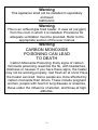
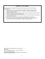
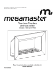
This appliance complies with the requirements of SANS 1539 Permit numbers: 1185-20-RSA-08 Flue-Less Fireplace and Gas Grate Models 1100 DS Read these instructions carefully and retain for future reference 2 Technical Data Model Number 1100 Gas Type LP Gas Operating Pressure 2.8 kPa Heat Output 38.8MJ/h Gas Consumption 775g/h Jet Marking 52 Jet Diameter 1.6mm Important information for the owner/user of this appliance. This appliance may only be installed by a registered Gas Installer. A registered gas installer is issued with a registration/identity card by SAQCC-Gas, the government appointed registration body for all gas installers. This identity card bears a photograph of the registered installer to whom the card was issued, together with his or her registration number, and a statement indicating the type of installation the person is qualified and registered to undertake. For the Megamaster Flue less fireplace the type of installer required is one that is registered to undertake Domestic LPgas installations. Upon completion of the installation the installer is required to issue the owner/user with a Certificate of Conformity. This is a legal requirement. You will be asked to countersign the certificate. The installer is also required to instruct you in the safe operation of the appliance and the gas system as a whole. Keep the certificate in a safe place as this may be required by your insurance company. It is recommended that you make copy of the certificate and keep this off site. The certificate will also be required should you need to repair or call a technician to carry out any maintenance on the gas system. Important information for the installer This appliance has been tested for compliance with the requirements of SANS 1539.A Safe Appliance Permit has been issued for this appliance and the permit number is shown on the front over of this booklet. The appliance is to be installed in full compliance with the requirements of SANS 10087-1.Upon completion of the installation you are by law required to issue the owner/user with a Certificate of Conformity. Both you and the owner/user are required to sign the certificate. It is your responsibility as an installer to instruct the owner/user in the safe operation of the installed system and appliance. This instruction should include information on the changing of cylinders. 3 1. Introduction Thank you for purchasing your new Megamaster LPgas Flue less Fireplace. This new design is fully manufactured in our well equipped overseas factory and is tested and inspected prior to shipping. It is important that you read the following instructions carefully to ensure that you achieve the best possible results from your new appliance. Please note that this appliance is for domestic use only. The manufacturer and /or its agents shall not be held responsible for injuries or damages caused by faulty or incorrect installation of the appliance. 2. Safety Information This appliance is designed to be used with a 48 kg LPG cylinder It must be used with a 2,8 kPa regulator that complies with the requirements of SANS1237 Never connect the appliance directly to the cylinder. Failure to use a regulator will damage the appliance and is an unsafe practice. Do not use this appliance if it is leaking gas (see notes below on how to check for a gas leak) The gas cylinder must be installed outdoors Always change the gas cylinder away from any sources of ignition Keep the gas cylinder away from heat and / or flames. The gas cylinder should not be dropped or handled roughly! Replace the protective cap on the cylinder after disconnecting the cylinder from the appliance. Cylinders must be stored outdoors in an upright position and out of the reach of children. Keep young children away from the appliance when it is in use. In the event of burn back, (where the flame burns back to the jet) immediately turn off the gas supply at the burner control valve. After ensuring that the flame is extinguished, re-light the appliance as described in Section 3 below. Should the appliance again burn back, close the control valve and the cylinder valve and call a technician to examine the installation and make any necessary repairs to the appliance. If there is an apparent gas leak on the appliance e.g. a smell of gas, close the control valve on the appliance. Make sure that there are no naked flames within 5 metres of the appliance and check for leaks as described below. Do not check for gas leaks with a flame as this is extremely dangerous. To check for a gas leak, use a brush dipped in a soapy water solution (e.g. water with dish washing liquid added) and applies the brush to the suspect areas such as the cylinder valve spindle or where the regulator screws into the cylinder. Also check the joins between the hose and regulator and between the hose/pipe work and appliance. If there is a leak then bubbles will form. Should this happen, turn off the gas supply at the cylinder valve. Inspect the condition of the seal fitted on the regulator and ensure that it is in good condition. Refit the regulator to the cylinder and re-test using the soapy water solution. If the leak persists or if the leak appears to be coming from the appliance itself, then turn off the gas at the cylinder and call in a technician to examine the appliance and gas supply system and to fix the leak. Do not use the appliance if there is a smell of gas or a suspected gas leak. If the appliance is not to be used for extended periods e.g. whilst away on holiday or during the summer season, always close the valve of the gas cylinder and preferably disconnect it from the system This appliance is fitted with an Oxygen Depletion Sensor for your safety. In the event that there is insufficient ventilation in the room in which the appliance is installed and used, the Sensor will shut off the gas supply. Do not interfere with or remove or modify this device as it is dangerous to operate the appliance if the Sensor is not present or has been damaged. The appliance is fitted with a data plate with information similar to that shown on Page 2 of this booklet. Do not remove this data plate as it will be required by service technicians and the supplier should you need to call for service assistance. 3. Preparing the gas grate for use Carefully pour the supplied base material into the burner tray until it is level with the edges of the tray. 4 Please note that the pebbles are not factory produced and will therefore vary in size and shape. This is of no consequence to the safe operation of the appliance. The variances in size may be in fact assist in creating a non uniform and attractive layout of the pebbles on the base material. The number of pebbles supplied with the appliance is pre determined after factory trials carried out under controlled conditions, and will give a good flame pattern as well as the required amount of heat from the fire. Adding more pebbles will decrease the flame effect and may lead to sooting of the pebbles. Place the pebbles randomly on the base material until the burner tray is completely covered with pebbles. Do not place the pebbles on top of one another as this will not improve the flame appearance and may negatively affect the burner performance. When placing pebbles always make sure that they are positioned in a manner that will not cause them to fall out of the burner tray. Once the pebbles have been laid as described above it is time to light the gas grate for the first time. 4. Lighting Procedures Before lighting the fireplace make sure you are familiar with the section on checking for gas leaks as described on page 3 of this booklet. Make sure that the cylinder valve has been turner to the open position, never open a cylinder valve to its fully open position. It is sufficient to open it no more than 1½ turns. Opening it further will not increase the amount of gas supplied to the appliance. If you do smell gas when lighting the appliance, turn off the gas at the appliance and check for gas leaks as described on page 3. If in any doubt also turn off the gas at the emergency shut off valve (also the isolator valve- if fitted) and the gas cylinder. If you are unable to trace the source of a leak then call a service technician to examine the complete installation before using the appliance. If you do trace a leak be aware that you may not make any adjustment to the installation when fixing a leak .As a user you are limited to ensuring that the connection of the cylinder is secure and that the rubber seal on the regulator is in good condition and in place. If there is a leak in the gas line or any of the joints or connections up to and within the appliance, then this corrective action must be carried out by a registered installer or gas appliance technician The appliance is fitted with a manually operated Piezo Ignitor built into the appliance control valve which ignites the gas grate when the control valve knob is turned to the ignite position. The control valve is situated under the hinged cover on the left or right of the burner tray of the appliance. (See Figs. 1 &3) After checking that the gas supply to the gas grate is turned on, by opening the cylinder valve and the emergency shut off valve (also the appliance isolator valve- if fitted), push the control knob (See Fig. 3) in and whilst holding it in the pushed in mode, turn it anticlockwise to the ignite position . This should ignite the burner. If the burner does not ignite the first time repeat the above step by turning the control knob back to the off position and try again. You will not be able to turn the knob to the ignite position unless it remains in the pushed in position whilst turning the knob. Once the pilot burner is lit, continue to hold the burner control knob in the pushed in position for approximately 15 seconds and then adjust the flame by turning the control knob in an anti clockwise manner to the give the level of heat you require. When the control knob is turned fully anticlockwise, the gas grate is at its highest heat setting. To reduce the heat output turn the control valve in a clockwise direction. Should the burner not ignite using the built in Piezo ignitor it is possible to ignite the pilot burner using a match. To do this first ignite the match and then push the burner control knob in and turn it to the ignite position and offer the lit match up to the pilot burner whilst holding the control knob in the pushed in position. 5 This should ignite the pilot burner. Continue to keep the burner control knob pushed in for approximately 15 seconds before releasing it and turning it in an anti clockwise direction to the on position. You can how adjust the flame height to the required setting. 5. Shutting down the appliance after use To turn off the appliance simply turn the burner control knob in a clockwise direct to the off position. 6. Safety information when using the appliance Ensure that there are no flammable materials immediately in the front of the appliance.(See Fig. 4) Do not place clothes in front of the heater to dry them. If there are young children or animals in the room when the appliance is in use, it is advisable to place a fireguard in front of the appliance. Never try to move the pebbles if they are hot or whenever the heater is in use. This an extremely dangerous practice. 7. Ventilation The firebox is designed specifically to be installed in a purpose built masonry or brick fireplace. If the fireplace has a chimney this should be blocked off completely, or if a damper is fitted in the fireplace, this must be permanently fixed in the closed position. This appliance is a flue less product and as such certain clearly defined ventilation requirements must be observed. These ventilation requirements concern provision of adequate fresh air ventilation for flue less appliances. The requirements are quite specific. The installer is required to follow the requirements which are covered in SANS 10087-1 and these requirements are also explained in this booklet. This appliance may not be installed in separately enclosed bathrooms. If the room volume in which this appliance is to be installed is less than 79m for the Model LVFD 900 or 92 m for model LVFD 1100, then it is a legal requirement that permanent ventilation shall be installed before the appliance may be used. In the case of open plan layouts, and providing that there are no inter leading doors which may be closed, it is permissible to use the total volume of the combined areas in determining if the minimum room volume has been met. If by including the volume of the adjoining room the total volume does not meet the minimum sizes indicated above, it is a requirement that permanent ventilation be fitted. It is to be noted that he appliance may not be installed in a bedroom unless the minimum room volume indicated in the previous paragraph has been met AND permanent ventilation is fitted. Note that even if the bedroom volume is greater than the minimum indicated in the above paragraph, permanent ventilation is required. This requirement is mandatory and the installer has no discretion in this matter. The boxed warnings on page 9 of this booklet must be noted. This is for the safety of the occupants of the room. See below for the permanent ventilation minimum sizes which are based on the maximum heat input of the installed appliance. Where the room volume determines that permanent ventilation openings are required, there shall be one opening at floor level and one at ceiling level preferably on opposite or adjacent walls. Each of these opening shall have a fresh air area of not less than 6,5 cm per MJ/h of the appliance heat input. The means that for model LVFD 900 each of the openings shall be not less than 189 cm3 and for model LVFD 1100 each of the openings shall be not less than 221 cm3. These openings must never be blocked Permanent ventilation openings shall be directly to the outside in order to ensure the provision of fresh air into the room in which the appliance is installed. Flue less appliances add moisture to a room and in addition to the fact that it is dangerous to use this type of appliances without adequate permanent ventilation, to do so may cause 6 mildew to form on wallpaper and furnishings. This is a direct result of insufficient ventilation into the room. Should this happen the installer should be requested to re-examine the installation with specific regards to the provision of adequate ventilation. If installed in locations higher than 1500 metres above sea level, users may experience an unexpected heater shutdown. This is most likely due to the Oxygen Depletion Sensor automatically shutting down the heater and indicates the need for increased ventilation. A short term solution is to open a window, but correct way to address the problem is to increase the size of the permanent ventilation openings to prevent the re-occurrence of the problem. 8. Care & Maintenance Your appliance is manufactured from high quality materials and components that are specifically selected and developed for serviceability. With proper care and, your appliance will provide you with many years of satisfactory performance and trouble free service. It is recommended that this appliance is serviced annually by a registered gas installer. Before undertaking any cleaning or maintenance work on the appliance, make sure that it is not hot and that the gas supply to the appliance is turned off. Never use abrasive cleaning solutions or substances on the polished surface of your fireplace as the use of this type of cleaner will permanently damage the polished surface. Use only a soapy water solution applied with a soft cloth. 9. Installation instructions 9.1 Firebox The wall into which the firebox is to be fitted will need to be built around the firebox. To achieve an acceptable appearance it may be necessary to adjust the wall e.g. adding or removing plaster, to ensure that the fascia or bezel of the firebox fits flush up against the wall surfaces on both sides of the wall. The stainless steel firebox is of double wall construction and therefore no insulation is required between the firebox and the fireplace which must be of a non combustible material. The base on which the firebox is to be placed in the wall opening shall be level and built of non combustible material. As the control valve protrudes below the underside of the firebox it is necessary to provide a recess in the bottom of the wall opening to accommodate the valve assembly and also to provide a path for the primary air required by the burner. See the important note at the end of this section and figs 5 and 6. When fitted, the firebox fascia must fit flush up against the wall at the front of the fireplace. If a damper is fitted into an existing chimney structure it is recommended that it be fixed in the fully closed position. If the steel firebox is to be installed into a brick or masonry fireplace that has previously been used for a coal fire, before installing the firebox, carefully check that the chimney is clear of excess soot or any loose materials to prevent any risk of this catching fire. An existing chimney should preferably be completely blocked off before installing the stainless steel firebox. This appliance is only for use without a flue. Before placing the stainless steel firebox into position examine the gas grate so that you are aware of the position of the gas inlet point. The gas line needs to be routed under the base of the burner tray. It may enter the space from the left or right of the firebox. Important! The gas grate / burner assembly need a permanent and fixed source of primary air to function. Failure to provide this will result in a dangerous condition due to the increased amounts of carbon monoxide that will be created if primary air is not provided. Provision for this must be made before placing the firebox into position. See Figs 5 & 6 for details. 9.2 Gas Grate installation 7 This appliance is a flue less appliance. It is not to be used with a flue. Take note of the ventilation requirements indicated this booklet as well as the specific requirements in SANS10087-1 This appliance must be only with a regulator with sufficient flow capacity to provide an outlet pressure of 2,8 kPa at the appliance when the appliance is turned fully on. The regulator must comply with SANS 1237 and unless of the inline type must be installed outside. If installed inside it may not be hidden in a cupboard or any closed recess that requires tools of any type to gain access to the regulator. It is important to ensure that the firebox is placed on a flat level surface. Failure to take note of this may lead to an irregular or unstable flame pattern. Note the safety distances from flammable materials given in Fig. 4 and ensure that these recommended safety clearances are in place before handing over the appliance. Use soft drawn copper pipe to connect the gas supply to the appliance. Flexible hose is not suitable as heat transfer may damage the hose. The gas consumption of the appliance is such that a minimum of 1 x 48 kg LPG cylinder is required. For convenience it is recommended that a 1 on/1 off installation be considered. Follow the notes on page 4 to prepare the gas grate for use. The gas grate is supplied with the correct amount of base material and the required number of pebbles. Before lighting the appliance for the first time carry out the pressure test. This should be done in the presence of the user. Always check the line pressure at the appliance. The minimum required line pressure at the appliance is 2,8 kPa. This is important to ensure that the appliance performance meets it designed efficiency and combustion safety levels. You are required to light the burner in the presence of the owner/ user and to instruct that person in the safe operation of the appliance and the complete installation. You are required to show the user how to connect and disconnect the cylinder(s) and to make sure that the importance of ensuring the regulator seal being in place and in good condition is understood. It is particularly important to show the user the position of the emergency shut off valve and if fitted, the isolator valve You are required to provide the owner/user with a completion certificate which must be dated and signed by both parties. Ensure that your name and SAQCC number appear on the certificate. 8 9 Warning This appliance shall not be installed in separately enclosed bathrooms Warning This is an unflued gas fired heater. It uses air (oxygen) from the room in which it is installed. Provisions for adequate ventilation must be provided. Refer to the appropriate section of the user manual Warning CARBON MONOXIDE POISONING CAN LEAD TO DEATH Carbon Monoxide Poisoning: Early signs of carbon monoxide poisoning resemble the flu, with headaches, dizziness or nausea. If you have these signs, the heater may not be working properly. Get fresh air at once! Have the heater serviced. Some people are more affected by carbon monoxide than others. These include pregnant women, people with heart or lung disease or anaemia, those under the influence of alcohol, and those at high altitudes. 10 11 12 WARRANTY DISCLAIMER Please note that the warranty on the product will not be honoured in the following circumstances: 1. If the product has not been installed by a SAQCC registered LPgas Installer. 2. If the owner is not in possession of a Certificate of conformity issued by the registered LPgas installer. 3. If the product has not been installed according to the requirements of SANS 100871and any applicable local authority by laws. 4. If there is evidence that the product has not been used correctly and/or according to this instruction manual. 5. If the owner or anyone else has made any modifications to the product. 6. If the ownership-card and required information was not returned with proof of purchase to the manufacturer within 90 days of original purchase. Manufactured for and distributed in South Africa by: Megamaster Tel: (+27) (012) 802 1515 Fax: (+27) (012) 802 1516 Web: www.megagroup.co.za No 8, Donkerhoek, Pretoria East (Old Bronkhorstspruit Road) PO Box 15, Woodlands 0072 13