1
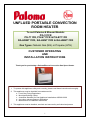
UNFLUED PORTABLE CONVECTION
ROOM HEATER
To suit Paloma & Rheem Models:
PG-511FR
PG-711FR, PG-S711FR & PG-B711FR
RA-HNW711FR, RA-HNS711FR & RA-HNB711FR
Gas Types: Natural Gas (NG) or Propane (LPG)
CUSTOMER OPERATING
AND
INSTALLATION INSTRUCTIONS
Thank you for purchasing a Paloma/Rheem Convection Gas Space Heater
1. To operate this appliance safely and correctly, please read these instructions thoroughly.
2. This appliance must be installed in accordance with:
a. Local Gas Fitting Regulations
b. Municipal Building Codes
c. Australian Standard for Gas Appliance Installations AS5601-2002
d. Any other relevant Statutory Regulation
e. Manufacturer’s installation instructions
3. This appliance must be installed, serviced and removed by an Authorised person.
1
Warranty Information
Please Record Below
Your Retailer: …………………………………………………………………………………..
Address: ………………………………………………………………………………………..
Phone: ………………………………………………………………………………………….
Date of Purchase: …………………………………………………………………………….
Note: There is no need to post this guarantee back, simply keep it in a safe place together with a
copy of your purchase invoice.
Description
Combustion Chamber
All Other Parts
Domestic Applications
Commercial Applications
Parts
Labour
Parts
Labour
10 Years Pro rata (*)
5 Years
1 Year
1 Year
5 Years
5 Years
1 Year
1 Year
(*) Combustion chamber full replacement parts cost in the first five years, reducing 20% per year thereafter.
Please note: The five-year domestic warranty is only applicable for units purchased after 1 March 2008.
Warranty Conditions:
•
•
•
•
•
•
•
•
•
•
•
The warranty periods that are allocated for domestic use are based on heating requirements of a typical
domestic dwelling. The warranty periods allocated under commercial use are for all other applications.
Terms of this warranty are effective from date of purchase and the attending service technician reserves
the right to verify this date by requesting a copy of the purchase invoice prior to commencement of any
warranty work.
These units must be installed correctly and the installation must conform to all regulations.
These units must be serviced, installed, commissioned, repaired, and removed by an authorised person.
No parts must be modified or removed from the unit.
These units must be operated and maintained in accordance with manufacturer’s operating instructions.
This warranty applies only to the components supplied by the manufacturer. It does not apply to
components supplied by others.
Where a failed component is replaced under warranty, the balance of the original appliance warranty will
remain effective. The replacement part or appliance does not carry a new warranty.
We reserve the right to transfer functional components from defective appliances if they are suitable.
We reserve the right to have the installed product returned to the factory for inspection and repair.
Please note: general cleaning, maintenance, operation and wear & tear are not covered by the
guarantee. Calls of this nature will be chargeable.
Warranty Exclusions:
The following exclusions may cause the warranty to become void and may result in a service charge and
costs of parts (if required):
•
•
•
•
•
•
Accidental damage and Acts of God.
Failure due to abuse or misuse, improper maintenance, failure to maintain or improper storage.
Failure due to incorrect or unauthorised installations.
Failure or damage caused by alterations, service or repair work carried out by persons other than our
authorised service technicians or agents.
Where it is found that there is no fault with the appliance and the issue/s are related to the installation or
is due to the failure of electric or gas supplies.
We do not accept liability for any consequential damage or any incidental expenses resulting from any
breach of the warranty OR claims for damage to a building or any other consequential loss either directly
or indirectly due to fire or any other faults.
2
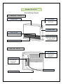
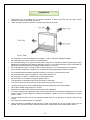
Product Overview
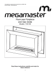
General Design Layout
<< FRONT VIEW >>
Control Panel
Carry Handle
Use when carrying
the heater
Warning Label
Warm Air Inlet
Warm air is discharged.
Rating Plate
Shows model No.
Gas Type, Month
of Manufacture
Louvre
<< REAR VIEW >>
Air Filter (1)
Prevents dust
entering the
appliance.
Air Filter (2)
Prevents dust
entering the
appliance.
Gas Hose
Electric Plug
3
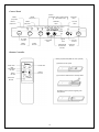
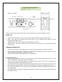
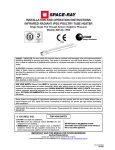
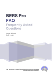
Control Panel
DISPLAY SCREEN SET TEMP . ROOM TEMP.
TIME. ERROR CODE ( ) TIMER2 [OFF] LIGHT TIMER 1 [OFF] LIGHT ECONOMY LIGHT TIMER2
[ON] LIGHT TIMER 1 [ON] LIGHT ON OFF TIMER
2 TIMER 1 ON / OFF LIGHT ECONOMY ON OFF AM FM SET SET TIMES OVER‐RIDE LIGHT ROOM FILTER ON OFF OVER RIDE TEMP/TIME SET‐TIMES BUTTON TIMER1 BUTTON CHILD LOCK LIGHT TIMER2 BUTTON FILTER LIGHT TEMPERATURE ADJUSTMENT BUTTON ON / OFF BUTTON OVER‐RIDE BUTTON Remote Controller
Battery replacement (AAA size 1.5V 2 pieces)
(1) Remove access panel. ON BUTTON TEMP ADJUSTMENT BUTTON TIMER1 BUTTON OFF BUTTON
ON OFF DOWN UP TIMER 2
BUTTON (2) Ensure that batteries are correctly fitted.
1 TIMER 2 OVER‐RIDE BUTTON OVERRIDE (3) Replace access panel and gently push into position. 4
Features
•
5.9 Star Energy rating.
•
One touch ON / OFF button.
•
Electronic ignition.
•
Adjustable room temperature - you can adjust the room temperature by pressing the up and down
arrows on the control panel.
•
Dual timers – the heater can be set to operate automatically at two separate periods of the day.
•
Remote control operation – ON / OFF, temperature control (up/down), timer 1 & 2, override.
•
Child lock function prevents accidental operation as well as children interfering with the controls.
•
Automatic Economy function – when the room reaches the required temperature the heater
automatically decreases room temperature by 1 deg C for every 30 minutes up to 2 deg C.
•
Preheat function allows the heater to automatically operate one hour prior to the programmed starting
time.
•
Override function allows the user to manually override the preset program and operate the heater.
•
NOX emissions - lower than the requirements of the Australian Standard.
•
Energy efficient 7 stage modulating gas valve.
•
Filter Clean Warning Device - When the air filter is clogged or hot-air outlet is blocked, the filter safety
device will switch off the heater and the filter light will flash.
•
Anti-tilt Safety Switch automatically shuts off gas flow if the heater is knocked or bumped.
•
Oxygen Depletion Safety System automatically shuts off gas flow if the oxygen level in the room drops
below a safe level.
•
Flame Failure Device prevents flow of gas to burner if ignition fails or flame goes out.
•
Power Failure Device prevents flow of gas to burner if there is a power failure.
•
Overheat Safety Device – if the fan stops rotating for any reason the overheat switch shuts off the gas
supply.
•
Manufactured in Japan.
5
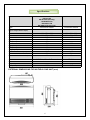
Specifications
MODEL
Type
PG-711FR
PG-S711FR
PG-B711FR (NG only)
RA-HNW711FR
RA-HNS711FR
RA-HNB711FR (NG only)
PG-511FR
Convection Heater
Convection Heater
494 x 531 x 226
494 x 531 x 237
NG
25
6.2
LPG
23
6.2
6.1
Φ 9.5
5.9
62
494 x 531 x 226
494 x 531 x 237
NG
Off White, Silver & Charcoal
Off White
11.7
11.7
12.7
12.7
DIMENSIONS: (mm)
(Approx: Height x Width x Depth)
NG
LPG
GAS INPUT - NG
High (MJ/h)
Low (MJ/h)
GAS INPUT - LPG
High (MJ/h)
Low (MJ/h)
Output (kW)
HOSE Connections (mm)
STAR ENERGY RATING
MINIMUM ROOM SIZING (Cu.M)
COLOUR
NET WEIGHT
NG (KGS)
LPG (KGS)
EXTERNAL DIMENSIONS FOR NATURAL GAS UNIT (mm)
6
18.5
6.7
LPG
18.5
6.7
4.7
Φ 9.5
5.9
45
Preparation
(1) Remove heater from carton.
(2) Please ensure that the gas specified on the rating plate matches your gas supply. Using a different type
of gas may cause an explosive ignition resulting in injury, damage to heater or malfunction of the oxygen
depletion safety system. Do not install heater if it is the wrong gas type. Please contact your place of
purchase immediately.
(3) Check room sizing – refer specifications. Do not install if the actual room size is less than the specified
minimum room size requirements.
(4) A dedicated 240V Earthed 10 Amp power point must be used with this heater.
Notice to Victorian Customers: This appliance must be installed by a licensed person as required by the
Victorian Building Act 1993. Only a licensed person will give you a compliance certificate showing that the
work complies with all relevant standards. Only a licensed person will have insurance protecting their
workmanship for 6 years. Make sure you use a licensed person to install this heater and ask for a
compliance certificate. – Message from the Victorian Plumbing Commission.
Safety Instructions
To ensure safe and proper use of this heater, please read these instructions carefully.
Danger – Indicates an immensely hazardous situation which, if not avoided, will result in serious
injury or death in the most extreme situations.
Warning – Indicates a potentially hazardous situation which, if not avoided, could result in serious
injury or death in the most extreme situations.
Caution – indicates a potentially hazardous situation which, if not avoided, may result in minor
injury.
Danger
If a gas leak is detected:
• Do not turn power switches on or off.
• Do not plug or unplug electrical appliances.
• Do not use the telephone.
Flame or sparks may ignite the gas and cause a fire:
• Cease operation immediately and close the gas valve.
• Open windows and doors for ventilation.
• Contact your gas supplier, a licensed plumber or Rheem Service on 131 031.
7
Warnings
•
For information on the gas consumption and gas type please see data plate.
•
Please ensure that the gas specified on the rating plate matches your gas supply. Using a different type
of gas may cause an explosive ignition resulting in injury, damage to heater or malfunction of the oxygen
depletion safety system. Do not install heater if it is the wrong gas type. Please contact your place of
purchase immediately.
•
Electrical supply must be 240v, 50 Hz.
•
Use only the gas hose supplied with the heater to avoid risk of gas leakage.
•
Ventilation and room sizing must comply with local regulations. This heater is not intended for a fireplace
insert.
•
Ensure your room is correctly ventilated while unit is operating. Continuous use decreases the oxygen
level in the room which activates the oxygen depletion safety system.
•
Do not allow curtains or other flammable materials or aerosol cans to come into contact with the heater.
It may cause a fire or the pressure in the aerosol-can may increase resulting in an explosion.
•
Do not use or store gasoline, benzene, aerosol or any other flammable material near this appliance. It
may result in a fire.
•
Do not post or allow children to post articles such as paper, cloth or any other foreign material into the
louvres or air inlet of the heater. Do not block the louvres or the air inlet of the heater. This may cause a
fire or overheat the appliance.
•
Do not leave the heater unattended or alight when you leave the house.
•
Do not sit, stand or sleep directly in front of the heater. Receiving direct heat continuously may cause low
temperature burns. The aged, children, a very tired person, a person with sensitive skin or an intoxicated
person must be supervised at all times.
•
If your heater fails to operate correctly or you detect any unusual odours during its operation, cease
operation immediately and close the gas valve. Refer to the trouble shooting section of these instructions
and if the problem cannot be fixed please contact your gas supplier or Rheem service.
•
This heater must be repaired or serviced by an authorised person. Repairs carried out by an
unauthorised person may cause abnormal operation. The heater must be serviced at least once every
three (3) years.
•
Do not place articles on or against or in front of warm air outlet or air filter of this appliance.
•
Do not spray aerosols in the vicinity of this appliance whilst it is in operation.
•
Do not use this heater in areas where spray painting is taking place or in areas such as hairdressers
where there may be lots of fluff and dust or where aerosols may be used.
•
All replacement parts must be approved Paloma spare parts.
•
This heater may circulate large volumes of air. If the air in the room contains any cigarette smoke or
cooking vapours, it may affect the appearance of carpets, furniture and drapes, etc.
•
Clean the air filter regularly (at least once a week).
8
Caution
•
Do not move the heater during operation.
•
Do not use for any other purpose other than for heating. Must only be used as a space heater.
•
Do not touch the warm air outlet during operation. Supervise young children or infirm persons near the
heater. Also ensure that children do not play with this appliance.
•
Do not sit, stand or lean on the heater.
•
Do not insert your fingers into the louvres or the air inlet of the heater.
•
Do not cut the electrical cord to extend the lead. Install the heater where the original electrical cord
reaches a wall socket.
•
Do not unplug or shut down during operation. This may cause overheating.
•
Do not place the heater near an opening door. The heater could be knocked over.
•
Do not touch the electric plug with wet hands as this could cause an electric shock.
•
Do not pull the electrical cord to unplug as this could break the cord and start a fire.
•
Place a flat board for stability when placing the heater on soft or thick carpet. Placing directly on to a
carpet may discolour the carpet.
•
Ensure that recommended clearances are maintained at all times.
•
This heater is designed for domestic household applications only. Using this heater in commercial
applications will shorten its life significantly.
•
In case of thunderstorms, cease operation and unplug the electrical cord.
•
Do not use sprays containing silicon in the vicinity of the heater. It damages the oxygen depletion safety
device.
•
Do not install in a place where the heater may be affected by wind. The flame could be blown out by a
strong wind.
•
If the heater is shut off by the oxygen depletion safety system, please ensure you ventilate the room
immediately for satisfactory combustion.
9
Installation
•
This heater must be installed with a minimum clearance of 50mm from the rear and sides. These
clearances must be maintained at all times.
•
There must be a minimum clearance of 750mm from the hot air outlet.
•
Do not install in a room with inadequate ventilation – refer to Australian Standard AS5601.
•
Do not install on an uneven surface or a vibrating floor.
•
Do not install directly on to carpet or timber floor or vinyl floor or cork floors. Heat emanating from these
appliances may discolour the carpet or damage your floor. It is recommended that a mat or flat board be
placed in front of this appliance extending at least 800mm in front of it.
•
Do not install near a door or windy location or under shelves or in a confined space. E.G; fireplace.
•
Do not install in a bedroom or bathroom or combined living/sleeping areas or toilets or sauna.
•
Do not install where flammable materials are likely to come into contact with the heater.
•
Do not install where water may splash or near another heat source.
•
Do not install in a caravan, mobile home or recreational vehicle.
•
Do not connect to a Propane (LPG) gas cylinder indoors.
•
This appliance is not designed to be built into walls or cupboards.
•
If you move house check the gas type in the house where you are moving to.
•
The bayonet plug on the factory fitted flexible hose simply plugs into your bayonet fitting.
•
Do not place heater against wall or on a shelf.
•
Always place heater on flat surface and away from strong draughts.
•
It is recommended that a dedicated 240V 10Amp power point be used with this appliance. Do not use
power boards or double adaptors to operate this appliance. Heater must not be located below a power
socket – outlet.
•
Turn the heater off after use. Do not unplug the heater while it is in operation or while the fans are still
cycling.
•
Do not move the heater while it is in operation.
•
When the heater is operated for the first time or after long periods of non use a slight odour may be
emitted, this is normal. However if odours persist switch off the heater and contact Rheem Service.
10
Operating Instructions
Before you begin ensure that the gas hose connector and electrical cord are plugged in correctly.
START UP
•
Press the ON / OFF Button once to start the heater and the operation light (green) will light up.
•
After a short delay the combustion light (red) will light up, this indicates proper ignition has been
achieved and the burner is on.
•
Set temperature and room temperature are displayed on the screen.
•
When the ON / OFF light is glowing green the heater can be switched on by pressing the Remote
Control button.
TURNING HEATER OFF
•
Press ON / OFF button. The ON light goes out. Then press the OFF button on Remote Controller.
•
After the heater is turned off the convection fan will continue to operate for up to 4 minutes. This is to
lower the temperatures inside the heater and is normal.
•
Please do not unplug the heater while the fan is still operating.
Important Information:
• When using the heater for the first time or after long periods of disuse, ignition may not occur the first
time it is operated as there may be air within the pipes.
•
The unit may make noises after igniting or extinguishing the heater. This is due to expansion and
contraction of the heater components and is normal.
•
If the heater fails to light, repeat the procedure after first pressing the ON / OFF button to turn the unit off.
•
Do not start then stop immediately. This may cause the heater to overheat or the filter light to come on.
•
The economy operation will not function if the set temperature reaches a temperature in excess of the
room temperature.
•
For safety reasons the heater will automatically stop after 8 hours of continuous operation except when
the timers are used.
11
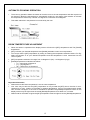
AUTOMATIC ECONOMY OPERATION
•
The economy operation allows the heater to heat the room to the set temperature and after a period of
30 minutes it allows the temperature to automatically reduce by one degree. After another 30 minutes
the temperature is reduced by a further one degree to a maximum of two degrees.
•
This subtle reduction in temperature is not noticed by the user.
ROOM TEMPERTATURE ADJUSTMENT
•
When the heater is operational the display screen will show the [SET] temperature and The [ROOM]
temperature:
•
[SET] indicates your desired temperature and [ROOM] indicates current room temperature.
•
You can pre-set the [SET} temperature by raising or lowering the temperature selection buttons. For Eg;
Select 22 Degrees C as your desired temperature and this temperature is then memorised into the
control system.
•
[SET] temperature selection can range from 16 Degrees C (low) – 26 Degrees C (high).
•
[ROOM] temperature is indicated as follows:
o {L} – lower than 0 Degrees C
o {1} – {30} Degrees C
o {H} – Higher than 31 Degrees C
Important Information:
• Please assume the Room temperature is not an exact temperature.
•
Your room may not arrive at the [SET] temperature or may exceed the [SET] due to the size of room,
construction of room, location of the heater or external temperature. If this occurs please switch heater
OFF and then ON again. In the case of immediate re-operation the [ROOM] temperature shown on the
display screen may be higher than the actual [ROOM] temperature for at least 3 to 4 minutes.
•
Please note for the heater to ignite the [SET] temperature must be higher than the [‘ROOM] temperature.
12
OVER-RIDE FUNCTION
The OVER-RIDE function allows the user to manually over-ride the preset program to operate the heater.
[Press OVER-RIDE button]
Over-ride operation is switched ON:
•
The OVER-RIDE light glows
•
After combustion the ON / OFF light glows red.
•
Set temperature and Room temperature will appear on the screen.
Over-ride operation is switched OFF:
Over-ride light glows.
ON / OFF light glows green and timers are ready.
After the heater turns off the convection fan will continue to operate for up to 4 minutes. Do not unplug while
fan is operational.
Between Timer Operation
Press {OVER-RIDE} button ON …The heater operates while the timers are on hold.
Press {OVER-RIDE} button OFF…The heater turns off and the preset program will resume.
During Timer Operation
Press {OVER-RIDE} button ON …Stops operation.
Press {OVER-RIDE} button OFF…The heater will operate again.
13
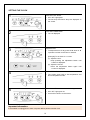
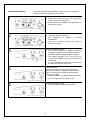
SETTING THE CLOCK
1
Press ON / OFF button.
•
ON / OFF Light glows
•
The Set temp and Room temp are displayed on
the screen.
2
Press SET TIMES button
3
Adjust the time
•
•
Time is displayed.
To adjust the time of day press the ▼ down or ▲
up button until the correct time is reached.
[Example] To set clock for 11:12am
(1) Adjust the hour.
Keep pressing the adjustment button until
11.00am is displayed.
(2) Adjust the minute.
Press the adjustment button again until
11:12am is displayed.
4
Press SET TIMES five times.
5
Press ON / OFF button to exit clock setting mode.
•
The screen goes back to Set temperature and
Room temperature mode.
•
ON / OFF Light goes out.
•
Clock will be shown on the screen.
Important Information:
If the heather is unplugged or if there is a power failure please reset the clock.
14
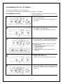
PROGRAMMING THE ON / OFF TIMER(S)
Two timers are available – Timer 1 and Timer 2.
You are able to set the start time and shutdown time for TIMER 1 and TIMER 2.
PROGRAMMING THE TIMER
Before programming the Timers, please ensure that
the correct time is set.
1
Press ON / OFF button
• ON / OFF Light glows.
2
Press SET TIMES button twice.
• The TIMER 1 “ON” light flashes.
3
Adjust TIMER 1 “ON” or start up time as required.
• To set the Timer 1 “ON” time press the ▼ down
or ▲ up button until the correct time is reached.
•
•
The Set temp and Room temp are displayed on
the screen.
The TIMER 1 time is displayed on the screen.
[Example] To set the TIMER 1 “ON” time to 5:30AM.
(1) Adjust the hour
(2) Keep pressing the adjustment button until
5:00AM is displayed.
(3) Adjust the minute.
(4) Press the adjustment button until 5:30AM is
displayed.
4
Press SET TIMES button.
• TIMER 1 “OFF” light flashes.
5
Adjust TIMER 1 “OFF” or shut off time as required.
• To set the TIMER 1 “OFF” time press the ▼
down or ▲ up button until the correct time is
reached.
•
15
TIMER 1 “OFF” time is displayed on the screen.
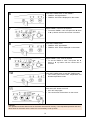
6
Press SET TIMES button to Set TIMER 2
• TIMER 2 “ON” light flashes.
•
7
8
Adjust TIMER 2 “ON” time as required
• To set the TIMER 2 “ON” time press the ▼ down
or ▲ up button until the correct time is reached.
Press SET TIMES button
• TIMER 2 “OFF” light flashes.
•
9
10
11
TIMER 2 “ON” time is displayed on the screen.
TIMER 2 “OFF” time is displayed on the screen.
Adjust TIMER 2 “OFF” time as required
• To set the TIMER 2 “OFF” time press the ▼
down or ▲ up button until the correct time is
reached.
Press SET TIMES button to exit SET TIMES mode.
• The screen goes back to SET temperature and
ROOM temperature mode.
Press ON / OFF button to turn off
• ON / OFF lamp lights
•
The current time will be shown on the screen.
Caution
The operation and shut down times for the timers are stored in memory. If the requested operation and shut
down times for the timers are the same it is not necessary to set up anew.
16
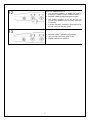
Press the TIMER/S button/s.
• You can select TIMER 1 or TIMER 2 or both by
pressing the TIMER 1 and/or TIMER 2 buttons.
12
13
17
•
Selected TIMER’s [ON] [OFF] lights will glow.
•
The TIMER operation is not set and will not
function if the TIMER’s “ON” and “OFF” lights are
not glowing.
•
If during operation combustion shuts down then
the ON / OFF light will glow green.
•
Selected TIMER 1 [ON/OFF] light flashes.
•
ON / OFF light turns from green to red.
•
Repeat operation for TIMER 2
Operation of timers
This section provides timer operation via the unit, but it is possible to
control the timers by using the remote control.
Please ensure that the main power is ON
• While main power is ON. ON / OFF light glows
green or glows red after ignition.
1
•
Please ensure the TIMER’s are programmed as
per previous section.
Please ensure you take the following steps.
• Is the gas valve fully opened?
2
•
Set temperature
temperature?
•
There are no objects in front of the louvre to
block the air outlet.
is
adjusted
to
desired
Press the TIMER/S button/s.
• You can select TIMER 1 or TIMER 2 or both by
pressing the TIMER 1 and/or TIMER 2 buttons.
3
•
Selected TIMER’s [ON] [OFF] lights will glow.
•
The TIMER operation is not set and will not
function if the TIMER’s “ON” and “OFF” lights are
not glowing.
•
If during operation combustion shuts down then
the ON / OFF light will glow green.
Pre-heat function:
[At one hour prior to the set time the heater will
operate automatically – Example; If the ON time is
set for 5.30AM then the heater will automatically
start up at 4.30AM]
• Selected TIMER 1 or TIMER 2 [ON] light flashes.
4
•
ON / OFF light turns from green to red.
[Timer operation start time]
• Selected TIMER’s [ON] [OFF] light flash.
5
18
6
[Timer Operation shut down time]
• Selected TIMER’s [ON] [OFF] light glows.
•
Combustion shut down and the heater stands by
for timer operation.
•
ON / OFF light glows green.
Cancelling the timers:
•
Press ON / OFF button or OFF switch on remote control or Press the TIMER button.
•
To manually cancel the TIMER’s press the TIMER buttons and lights will turn off.
•
If the Child Lock function is activated, unlock and press the TIMER buttons to cancel the programmed
timers.
Important Information:
•
For safety reasons the heater will operate at 26°C automatically if the Set temperature for the TIMER
function is adjusted [H].
•
If the electric cord is unplugged or in case of power failure, the timers will be cancelled so the selected
timers will not operate. Please program the TIMER’s once again.
•
You cannot overlap set times between the two timers. If the timers are overlapped the time that is set first
will have priority and the timer set second will be cancelled.
•
The timer settings will continue to operate if they are not cancelled.
PRE-HEAT FUNCTION
This heater has a pre-heat function which operates the heater one hour prior to the programmed starting
time of the timer. This function will warm the room before the programmed starting time of the timer. This is
an automatic function and cannot be cancelled.
CHILD LOCK
This heater has a child-lock function which prevents accidental operation as well as children interfering with
the controls.
Lock function is activated via the operational panel.
Press adjustment buttons together for one second.
• Lock indicator glows.
Cancelling the lock
Press adjustment buttons together again.
• Lock indicator turns off.
Important Information:
If the heater is locked during operation it is only possible to press the ON / OFF button.
If child lock is activated when the heater is not operating no button on the control panel can be activated.
19
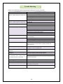
Trouble Shooting
Please check following important points before calling for a service technician:
CONDITION
SUGGESTED REMEDY
Check that the power cord is plugged in and the power turned on
The heater does not operate
(ON/OFF- operation light does not glow green) Circuit breaker or fuse is blown
Child lock is set
Check that gas is turned on
See that enough gas is left in LPG tank (in case of LPG appliance)
Does not ignite
(ON/OFF - operation light does not glow red)
Supply gas valve is not fully opened
Heater turns off during operation
Air filter is clogged and filter lamp flashes. Please clean air filter.
Air in gas hose
Check that hot air outlet is not blocked
Room does not become warm enough.
Set-temperature is set too low
Window or door is opened
Supply gas valve is not fully opened
Room size does not suit the heater capacity
Obstruction within 75cm in front of heater
Flame is extinquished during operation
Check that the room is well ventilated (Amount of oxygen inside the room
may be insufficient)
Gas smell
The hose is not securely connected
The hose is damaged
Heater smells during use
Turn off heater and call a licensed plumber
The heater will give out a strong odour if the room has been recently
painted or the floors have been waxed or polished. Ventilate room
properly before use
Heater smells or smokes when using first time The smell or smoke comes from oil used during manufacture. Operate
the heater for a while in ventilated room.
The fan keeps operating after the heater is
switched off
It stops after the temperature inside the heater has cooled. No action
required.
The heater creaks at the time of lighting or
switching off
The sound is caused by expansion and contraction of metallic parts when
the product is heated or cooled. No action required.
The heater does not ignite when using first
time in the season, when not used for a long
time or when the hose is re-connected.
There is air in the gas hose
Noisy during ignition or shutdown.
This is a normal operation noise.
The heater makes hissing noise.
This is a normal gas flow noise.
Does not ignite immediately after shutdown.
Please wait until the heater cools down. The heater will re-ignite
automatically 20 seconds later.
Repeat ignition procedure until the heater ignites (the lamp glows red to
purge the air in the hose)
Does not operate after is accidently unplugged. Please wait until the heater cools down. Try to restart after a few minutes.
20
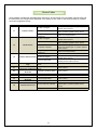
Error Codes
These heaters are fitted with self diagnostics electronics. Should a fault occur the heater will shut down and
the fault with a pair of digits will be displayed in the display screen. Refer to the following table for probable
cause and suggested remedy.
Error code
11
12
14
16
31
33
62
71
72
73
76
Problem
Probable Cause
Suggested Remedy
Clean Air Filter and operate again. If problem
Air filter is clogged
persists call for service.
Check gas valve is fully open and operate
Ingnition Failure
Gas valve is not fully opened
again. If problem persists call for service.
The gas supply volume is
Call for a licensed plumber.
inadequate
Clean Air Filter and operate again. If problem
Air filter is clogged
persists call for service.
Check gas valve is fully open and operate
Gas valve is not fully opened
again. If problem persists call for service.
Flame Failure
Open windows slightly or install ventilation
Insufficient ventilation
points and operate again. If problem persists
call for service.
The gas supply volume is
Call for a licensed plumber.
inadequate
Thermo switch is off
Call for service.
Clean Air Filter and operate again. If problem
Air Filter is clogged
Thermo Switch Cut Off
persists call for service.
Remove obstruction and operate again. If
Louvre is obstructed
problem persists call for service.
Room Temperature Too Room temperature thermistor
Call for service.
failure
High
Room Temperature
Room temperature thermistor
Call for service.
Thermistor is Abnormal failure
Overheat Thermistor is
Overheat Thermistor failure
Call for service.
Abnormal
Abnormal Fan Speed
Fan failure
Call for service.
Gas Valve is Abnormal Gas valve failure
Call for service
Thermocouple Circuit is
Thermocouple failure
Call for service
Abnormal
Gas Circuit is Abnormal Gas circuit failure
Call for service.
Place heater on a stable and level surface and
operate again. If problem persist call for
Tilt over switch is activated
Communication Error
service.
Wiring is disconnected
Call for service.
21
Inspection and Maintenance
Disconnect gas hose and turn heater off. Unplug and wait until the heater cools down.
•
•
•
Be sure to carry out daily inspection and maintenance.
Do not use the heater if you believe something is wrong.
It is recommended that your heater be serviced periodically.
Points to check
1.
2.
3.
4.
There are no flammable materials in the vicinity of the heater.
Air filter is fitting correctly and is not dirty.
The hose is correctly connected without kinking or twisting.
There is no damage to the electric cord.
Maintenance
Caution
Wear gloves
•
Be careful of sharp edges.
Warning
Do not use cleaning cloth, thinner, benzene, acid or alkaline detergent.
This will avoid discoloration of the paint and plastic components.
Maintenance of Heater Outer Jacket
(Preferable to clean once a month)
Keep the heater clean
•
•
Use damp soft cloth to wipe.
Use mild soapy water for severe dirt.
22
MAINTENANCE OF THE LOUVRE
Use vacuum cleaner to remove dirt from the louvre.
Make sure that the fan is not working before cleaning.
White powder may form on the louvre. Wipe off with soft cloth.
Caution
Do not press the louvre heavily. Do not apply strong pressure
to the Louvre.
•
The louvre may break causing discolouration of the
floor or carpet due to the change in heat
discharge.
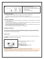
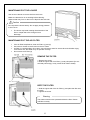
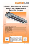
MAINTENANCE OF THE AIR FILTER
•
•
•
•
If the Air Filter lamp flashes, clean Air Filters (1) and (2)
Use vacuum cleaner to remove dirt on the Air Filters.
Air Filter (1) could be taken off to clean. Use mild soapy water for severe dirt and refit after drying.
If Air Filter is wet, the heater may not operate correctly.
Do not remove Air Filter (2)
REMOVE THE FILTER
1. Remove the screw.
2. Hold the upper side of Air Filter (1) and pull upward. (Do not
hold and pull strongly. It may cause the air filter to break).
REFIT THE FILTER
1. Hold the upper side of the Air Filter (1) and place the filter onto
the notch
2. Tighten the screw
Warning
The heater should not be operated without the filter. Please
refit filter correctly.
23
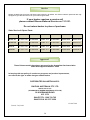
Service
Rheem Australia has a service and spare parts network in all states. Our service network personnel are fully
equipped to give the best service on your Paloma gas heater.
If your heater requires a service call
please contact Rheem National Service on 131 031.
Do not return heater to place of purchase.
State Service & Spare Parts:
QLD
SYD/CANB
NEWC
VIC
SA
WA
Service Tel
07 3213 0100
02 9684 9280
02 4961 3515
03 9212 8900
08 8343 0000
08 9351 4238
Service Fax
07 3213 0154
02 9684 9188
02 4961 3117
03 9212 8955
08 8359 6002
08 9353 4101
Parts Tel
07 3213 0102
02 9684 9282
02 4961 3515
03 9212 8911
08 8343 0044
08 9258 3099
Parts Fax
07 3213 0154
02 9684 9188
02 4961 3117
03 9212 8984
08 8359 6003
08 9356 9914
Approval
These Paloma models have been approved by the Australian Gas Association
under AGA Approval Number: 6540
In keeping with our policy of continuous progress and product improvement,
we reserve the right to make changes without notice.
DISTRIBUTED IN AUSTRALIA BY:
RAYPAK AUSTRALIA PTY LTD
ABN 65 078 743 414
(A DIVISION OF RHEEM AUSTRALIA PTY LTD)
39 KOORNANG ROAD
VIC 3179
SALES TEL: 1300 729 725
SALES FAX: 03 9757 3350
15-01875-00
Printed: July 2008
24