1
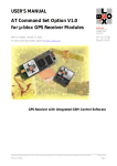
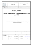
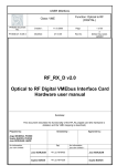
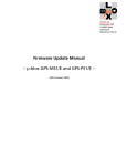
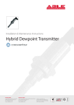
OC502-t_GBM_21311
HANDHELD
CALIBRATOR-MULTIMETER
OC502-t
Owner’s Manual
ORBIT CONTROLS AG
Zürcherstrasse 137
CH-8952 Schlieren/ZH
Tel: + 41 44 730 2753
Fax: + 41 44 730 2783
[email protected]
www.orbitcontrols.ch
2
Unpacking Instructions
Remove the Packing List and verify that you have received all equipment, including the following:
Orbit Controls Model OC 502-t Handheld Calibrator.
Operator's Manual OC 502-t.
If you have any questions about the shipment, please call the Orbit Controls Customer Service
Department.
NOTE
When you receive the shipment, inspect the container and equipment for signs of damage. Note
any evidence of rough handling in transit. Immediately report any damage to the Orbit Controls
customer service, Phone +4144 730 2753 or Fax +4144 730 2783 and to the shipping agent.
The carrier will not honour damage claims unless all shipping material is saved for inspection. After
examining and removing contents, save packing material and carton in event the reshipment is
necessary.
The shipment contains:
Calibrator-Multimeter Model OC502-t
Battery charger 12V DC, 600mA
Measure leads 4mm with banana and crocodile, 300 mm
length
Owner’s manual with Calibration Certificate
3
INDEX
CALIBRATOR-MULTIMETER OC 502-t
page 5
1
FUNCTION
5
2
OUTPUTS and INPUTS
6
3
L C D DISPLAY
6
4
KEYBOARD
7
5
SPECIFICATIONS
7
6
CALIBRATOR – FUNCTION SELECTION
6.1
Setting of the output current 0 - 22mA in steps or ramps
6.2
Direct setting of the output current between 0 and 22mA
6.3
Setting of the voltage output 0-14V in steps or ramps
6.4
Setting of mV Outputs 0–560mV and 0–28mV in steps or ramps
6.5
Thermocouple output in steps or ramps
6.6
Direct setting of the output voltage value 0-14 V, 0-560mV, 0-28mV and T/C
6.7
Selection of the display function
9
9
9
9
9
9
10
10
7
MULTIMETER - FUNCTION SELECTION
11
8
SOFTWARE CALIBRATION
8.1
Calibration of Calibrator
8.1.1 Current output 4-20mA
8.1.2 Current Sink 0/4-20m
8.1.3 Voltage Ranges 0-14V, 0-560mV, 0-28mV
11
12
12
12
13
8.2
13
13
13
13
14
Calibration of Multimeter Inputs
8.2.1 Current Input 0-100mA
8.2.2 Voltage Input 2V
8.2.3 Voltage Input 20V
8.2.4 Voltage Inputs 200V
9
LOGO
14
10
HARDWARE
14
11
TARA
15
12
FILTER
15
13
RAMPS
15
14
GRAPHICS
15
15
HANDHELD CALIBRATOR-MULTIMETER OC 502-V2-100
16
CALIBRATION CERTIFICATE
17
WARRANTY STATEMENT
18
4
CALIBRATOR - MULTIMETER OC 502-t
√
√
√
√
√
√
√
√
√
√
Current Calibrator 0/4 - 22mA, Source-Sink
Voltage Calibrator 0-14V
mV-Outputs 28mV and 560mV
DIN Thermocouples J, K, N, R, S, T, B, E
Multimeter ± 2V to ± 200V DC and ± 100mA
Calibrates and Measures simultaneously
Firm steps and continuous ramps
Direct value entry via the keyboard
Rechargeable Battery
Software calibration
Orbit Controls Model OC 502-t is a Calibrator-Multimeter which
generates currents 0/4-22mA in Source or Sink mode and Voltages 0 to
14V. External voltages ± 2V, ± 20V and ± 200VDC (firm ranges or
Autoranging) and currents up to ±100mA can be measured while the
calibrator generates the selected output signal. Due to this simultaneous
operation a response from e.g. external transmitters under test can be
measured with the calibrated signal from OC502-t. Both, the generated
calibration signal and the measured external signal are displayed.
For calibration of mV devices such as strain gauges chains, Millivolt outputs 0-28mV or 0-560mV with
high resolution are available.
Din Thermocouples J, K, N, R, S, T, B, E can be simulated in positive temperature range. The sensor
type will be selected and the required temperature entered with the keyboard. The display shows the
temperature, the mV output is at the output terminals. The junction is compensated for the ambient
temperature with internal sensor. The compensation can be switched-off.
OC502-t can be software recalibrated via the keyboard whenever required. The instrument is supplied
from internal rechargeable battery which permits 9 hour uninterrupted operation.
Back ground light can be switched on.
1
FUNCTIONS
OC502-t can be set for following functions by using the keyboard and the digital display:
Tara of the analogue outputs, the filter selection,
background light.
Range selection 0-28mV or 0-560mV
with resolution 0.001mV and 0.01mV.
Direct value entry via the keyboard.
The current can be set between 0 and 22mA,
the voltage between 0 and 14V.
Simulation of DIN - J, K, N, R, S, T, B, E
Thermocouples with or without
compensation.
Raising or sinking Ramps 0-14V or
0-22mA, with selectable steps.
Signal output of all Signal types in firm
steps such as 0-2-4-6-8-10-12-14V.
5
Calibrator
Current Source
Current Sink
Voltage Source
mV Source
DIN Thermometers
0 ... 22 mA
0 ... 22 mA
0 ... 14 V
0 … 28.000 mV and 0 … 560.00 mV
J, K, N, R, S, T, B, E
The calibrator functions are settable with three sliding switches:
ON-OFF
Power ON and OFF
SRC-I, SNK-I
Current Source 0-22mA, Current Sink 0-22mA
OUT-V, OUT-I
Voltage Output 0-14V, Current Output 0-22mA
ATTENTION!
In the Current Sink Mode the switches SNK-I and OUT-I have to be selected. Do not switch to OUT-V!
The Current and the Voltage Outputs might be destroyed!
Multimeter
Voltage Ranges
Current Range
Firm ranges
Autoranging
Firm range
± 2V, ± 20V, ± 200VDC
0 ... ± 200VDC
0 ... ± 100mADC
The Multimeter Functions can be set with the keys 100mA, AUTO, 2V, 20V, 200V.
2
OUTPUTS and INPUTS
CALIBRATOR:
MULTIMETER:
3
Voltage and Current Output: + OUT Voltage Input:
GND, IN-V
Current Input:
GND, IN-I
LCD DISPLAY
The LCD Display is divided into 2 sections. The upper part shows the multimeter functions, the lower
part shows the generated calibrator signals. A Bargraph in the middle displays the measured values as
an analogue function. The left side of the display shows various statements:
AUTO-FIX
200V
INP
NUM
RMP
SUP
99%
Automatic Range selection or Firm Ranges
Firm Ranges 2V, 20V, 200V, 100mA
The display shows the input signal. With FN the following functions can be set:
HLD Display HOLD
MAX Maximum Value Hold
MIN Minimum Value Hold
RST Reset the max. and the min. values to zero
Direct value selection with the keyboard
Automatic Ramp
Charger plugged, Battery is charged
Battery voltage shown in % of full capacity. Charge the battery when less
than 0% is displayed. Charge only with the enclosed original charger.
6
4
KEYBOARD
5
SPECIFICATIONS
CALIBRATOR
Outputs + OUT -
Current Source
Range
0 ... 22mA, max. Load 750 Ohm
Accuracy
± (0.05% from Value + 0.1% from Range)
Option: 0 … 110mA, see page 16: OC502-V2-100.
Range
0 ... 22mA @ max. 24VDC
Accuracy
± (0.05% from Value + 0.1% from Range)
Current Sink
Voltage Source
Range
Accuracy
Load:
0 ... 14 V, 0 … 560mV, 0 … 28mV
± (0.05% from Value + 0.1% from Range)
0 - 25V, maximum 1mA
0 - 560mV, 0 - 28mV: maximum load 1kOhm
Thermocouples
According to ITS 90:
Type
B, E, J, K, N, R, S, T
Range:
-270 ºC up to 1820 ºC
Accuracy:
± 0.3 – 2.5 ºC
Load:
maximum load 1kOhm
Could Junction compensation with SMT160 can be menu calibrated.
Working Ranges and specified Accuracies for Thermocouples
R
Range [°C]
Accuracy [°C]
-50 - 0
1.6
0 - 400
1.6
400 - 1760
1.6
S
Range [°C]
Accuracy [°C]
-50 - 0
2.4
0 - 500
1.9
500 - 1760
1.5
B
Range [°C]
Accuracy [°C]
50 - 800
2.5
800 - 100
1.5
1000 - 1820
1.3
J
Range [°C]
Accuracy [°C]
-140 - 0
1.1
0 - 700
0.6
700 - 1200
0.6
T
Range [°C]
Accuracy [°C]
-270 - -100
1.7
-100 - 0
0.7
0 - 400
0.3
E
Range [°C]
Accuracy [°C]
-120 - 0
1.1
0 - 370
0.3
370 - 1000
0.7
K
Range [°C]
Accuracy [°C]
-230 - -100
1.8
-100 - 0
0.8
0 - 1370
0.9
N
Range [°C]
Accuracy [°C]
-270 - -100
2.1
-100 - 0
1.4
0 - 1300
1.2
The accuracies shown are maximum values. Typical accuracies are lower.
7
Resolution
0…22.000mA, 0…14.000V, 0…560.00mV, 0…28.000mV, 0.1ºC
Tempco
± 25ppm/K
Ramps
Raising or sinking Ramps with programmable Steps ± 0.1mA, ± 0.05V,
± 2mV, ± 0.1mV, ± 5 ºC or ± 0.5mA, ± 0.25V, ± 10mV, ± 0.5mV, ± 20 ºC
Temperature
Working: -10 ºC ... +35 ºC, Store: 0 ... 45 ºC
Terminals
4mm gold plated terminals
ATTENTION!
In the Current Sink Mode the switches SNK-I and OUT-I have to be selected. Do not switch to OUT-V!
The Current and the Voltage Outputs might be destroyed!
MULTIMETER
Voltage:
IN-V:
Current:
IN-I:
Tara:
Filter:
Tempco:
Terminals
Inputs GND, IN-V, IN-I
Ranges
± 2V (1.83 MΩ), ± 20V (363 kΩ), ± 200V (333 kΩ)
Autoranging ± 200V DC
Accuracy
± 0.1% from range ± 1 Digit
Range
± 100mA DC (10 Ω)
The specifications are valid after
Accuracy
± 0.1% from range ± 1 Digit
a warm-up time of 10 min. and an
Tara can be activated with the keyboard.
ambient temperature of 23 ºC±2 ºC.
Averaging filter with filtering constants 0 to 9.
± 25ppm/K
4mm gold plated terminals
The calibrator output and the multimeter inputs have common GND.
MICROCONTROLLER
The Multimeter or the Calibrator functions can be selected with sliding switches. The settings and the
parameters are stored in internal memory. The instrument can be software calibrated via the keyboard.
Keyboard:
Rate:
Memory:
SUPPLY
Battery:
Charger:
The keys have to be pressed at least for 0.5 sec in order to permit the controller to accept
the command.
1 sample per 1 sec.
EEPROM.
Two 3.7V-2000mAh rechargeable Li-ion Batteries permit an uninterrupted operation of
9 hours with 20mA set at the calibrator output.
Mains voltage 100-240V, 48-60Hz / 12V-600mA DC. The battery requires 4.0 hours to be
fully charged. The green LED stops flashing.
8
6
CALIBRATOR - FUNCTION SELECTION
The calibrator functions are selectable with three sliding switches. The keyboard permits setting of
Ramps, Steps or direct Value entry.
The Multimeter is active all the time and can be simultaneously used with the calibrator. The function is
described in § 7.
The display is divided into two parts. The upper part shows the multimeter values, the lower part is
assigned to the calibrator outputs 0-20mA or 0-10V. The middle part is a Bargraph showing the values
as analogue information.
6.1
Setting of the output current 0 - 22mA in Steps or Ramps
Sliding switch to be set to SRC-I and OUT-I.
The key Clr set the output current to 4mA.
The key Up increases the output current in 0.20 mA steps.
The key Down decreases the output current in 0.20 mA steps.
The key Ramp activates the automatic ramp. To stop the ramp, press the key again.
The key Step generates the current steps of 4, 8, 12, 16, 20, 22mA
6.2
Direct setting of the output current between 0 and 22mA
Sliding switch to be set to SRC-I and OUT-I.
The key Num activates the numeric selection.
Enter the required value with the keyboard and press Enter.
To erase the last entry, use the keys ← and → .
6.3
Setting of the voltage output 0 - 14 V in Steps or Ramps
Sliding switch to be set to OUT-V.
The key Clr sets the output voltage to 0 V.
The key Up increases the output voltage in 0.10 V steps.
The key Down decreases the output voltage in 0.10 V steps.
The key Ramp activates the automatic voltage ramp.
The key Step generates voltage increments 0, 2, 4, 6, 8, 10, 12, 14V.
6.4
Setting of mV Outputs 0–560mV and 0–28mV in Steps or Ramps
Same like 0–14V voltage output. Menu selection: Select 2 or Select 3.
6.5
Thermocouple output in Steps or Ramps
Put the Sliding Switch into Position OUT-V.
Press MENU until the display shows VOLTAGE OUTPUT U.
Select 4 with MENU.
THERMOCOUPLE OUTPUT. Select the required Type.
Select Cold Junct. Comp. Select 1 (ON) for internal on-board compensation. Press MENU.
Select Unit Selection. Select 1 for degree Centigrade (ºC). Press ESC.
Key Clr sets the output signal to 0.0 ºC.
Key Up increases the Output mV in 10 ºC steps.
Key Down decays the Output mV in 10 ºC steps.
Key Ramp activates the automatic Ramp generation.
Key Step generates Output mV in Steps 0, 200, 400, 600, 800, 1000, 1200, 1400 ºC
RAMPS
The key Ramp activates the Ramp Generator. The display increments or decrement in steps selected
in the Menu and shows the symbol RMP. With the key Ramp the Ramp can be stopped. When
pressed again, the Ramp will continue from the value when it had been stopped. By keeping pressed
the key Ramp for several seconds, the Ramp will start from beginning.
9
6.6
Direct setting of the output voltage value between 0 and 14 V, 0-560mV, 0-28mV and T/C
Sliding switch set to OUT-V.
The key Num activates the numeric selection.
Enter the required value with the keyboard and press Enter.
To erase the entry, use the keys ← and → .
6.7
Selection of the display function
The key MENU selects following operation modes – see page 14:
TARA SELECT
Tara of the Multimeter input signal to Zero
FILTER DEGREE
Selection of averaging filter from 0 to 9.
RAMP SELECT
Activates Ramps:
1
2
3
4
Raising Ramp with 0.5mA, 0.25V, 10mV, 0.5mV and 20 ºC steps
Raising Ramp with 0.1mA, 0.05V, 2mV, 0.1mV and 5 ºC steps
Sinking Ramp with -0.1mA, -0.05V, -2mV, -0.1mV and -5 ºC steps
Sinking Ramp with -0.5mA, -0.25V, -10mV, -0.5mV and -20 ºC steps
GRAPHICS
Graphics of last 128 measuring points in the Multimeter function of the voltage
range up to 200V DC or currents up to 100mA DC.
BACKLIGHT
Back ground light: OFF or ON. With ON selection the display remains illuminated
for 20 seconds after pressing any key of the keypad.
VOLTAGE OUTPUT U
1
2
3
4
THERMOCOUPLE OUTPUT
1
3
5
7
Output Signal selection
Output 0…14V
Output 0…560mV
Output 0…28mV
Thermocouples Simulation
(Select 4 is activated)
Type B
Type J
Type N
Type S
2
4
6
8
Type E
Type K
Type R
Type T
Cold Junct. Comp.
Cold Junction Compensation can be activated or switched-off.
Unit Selection
EEprom Archive
ºC or ºF
Erase or Store the settings in internal EEPROM.
The key Esc terminates the programming mode and the display switches into the Measuring mode.
10
7
MULTIMETER - FUNCTION SELECTION
The multimeter is active all the time and can be simultaneously used with the calibrator.
The calibrator output and the multimeter inputs have common GND.
The upper part of the display shows the values and parameters of the Multimeter:
AUTO
FIX
Autoranging ± 2 ... ± 200VDC, settable with the key Auto.
Firm voltage ranges ± 2V, ± 20V, ± 200V DC, settable with Auto.
Firm current range ± 100mA DC, settable with 100mA.
With the key FN following mode of operation can be set:
INP
HLD
MAX
MIN
RST
8
The display shows the input signal
HOLD the display
The display shows the maximum value
The display shows the minimum value
The maximum and the minimum stored
values are erased
SOFTWARE CALIBRATION
The voltage and the current ranges of the multimeter and the output signals of the calibrator can be
precisely calibrated by using the keyboard. The calibration menu can be opened with the key Set.
A full calibration of all 5 ranges or selected ranges only can be approached. A five digit multimeter
10VDC and 20mADC will be used as well as a Voltage/Current calibrator 100mA, 2V, 20V and 200VDC.
1:
2-5:
6:
Calibrator Outputs
Multimeter Inputs
Hardware Configuration
To close the calibration menu press the key Esc.
11
8.1 CALIBRATION of CALIBRATOR OUTPUTS
8.1.1 Current Output 4-20mA
Outputs + OUT - with connected mA-Meter.
Sliding switch OUT-I.
Press 1. The display shows:
With the keys Up or Down appears the calibration constant 0. To change it, enter 11 with Up or Down.
The whole constant can be set with the keyboard. The 4.000 mA output current is set. Fine corrections
can be made with Up or Down. Press Enter to save the point. The display confirms with EEPROM.
Press Menu to next calibration range. The Display shows:
With the keys Up or Down set the output current to 20.000 mA.
Press Enter to store.
With Esc returns the display to calibration menu.
8.1.2 Current Sink 0/4-20mA
Sliding Switches OUT-I and SNK-I
Output Terminal + OUT connect with the Plus Terminal of external voltage source (max. 24V). Output
Terminal - OUT connect with the Minus Terminal of external voltage source with an mA-Meter connected
in serial. Press the key 1. The display shows:
With the keys Up or Down appears the calibration constant 0. To change it, enter 11 with Up or Down.
The whole constant can be set with the keyboard. The 4.000 mA output current is set. Fine corrections
can be made with Up or Down. Press Enter to save the point. The display confirms with EEPROM.
Press Menu to next calibration range. The Display shows:
With the keys Up or Down set the output current to 20.000 mA.
Press Enter to store.
With Esc returns the display to calibration menu.
12
8.1.3 Voltage Ranges 0-14V, 0-560mV, 0-28mV
Output Terminals + OUT – with external V-Meter
connected.
Sliding Switch in Position OUT-V.
Set the output voltage 2V with Up or Down
and store with Enter.
Select 10V Range with Menu, set the calibration
Constant with Up or Down and store with Enter.
Continue with Menu for calibration of Ranges
560mV and 28mV.
With the key Esc changes the display into the
calibration Menu.
8.2
CALIBRATION of MULTIMETER INPUTS
8.2.1 Current Input 0-100mA
Connect external Current Calibrator to Input Terminals GND and IN-I.
Press 2. The display shows:
Short the inputs. Press Enter to store the zero input.
Press Menu. The display changes to:
Apply 100mA from external calibrator.
Press Enter to store the 100mA full range input.
8.2.2 Voltage Input 2VDC
Connect 2VDC from external Voltage Calibrator to Input Terminals GND and IN-V.
Press 3. The display shows:
Short the inputs. Press Enter to store the zero input.
Press Menu. The display changes to:
Apply 2VDC from external calibrator.
Press Enter to store the 2V full range input.
8.2.3 Voltage Input 20VDC
Inputs GND and IN-V supplied from external voltage calibrator 20VDC.
Press 4. The display shows:
Short the inputs. Press Enter to store the zero input.
Press Menu. The display changes to:
Apply 20VDC from external calibrator.
Press Enter to store the 20V full range input.
13
8.2.4 Voltage input 200VDC
Inputs GND and IN-V supplied from external voltage calibrator 200VDC.
Press 5. The display shows:
Short the inputs. Press Enter to store the zero input.
Press Menu. The display changes to:
Apply 200VDC from external calibrator.
Press Enter to store the 200V full range input.
Press Esc to exit the calibration mode. The instrument is calibrated.
NOTE
Do not approach the calibration when the battery sign 0% at the display is illuminated. The instrument
has to be charged first.
9
LOGO
After the power has been switched on, the display shows a manufacturer Logo. Upon request this Logo
can be customized. Contact the manufacturer for more information.
10
HARDWARE
This menu step contains the settings of the output configuration 12 bit or 16 bit signal resolution, 20mA
or 100mA output current and the possible correction of the cold junction compensation. The Option
100mA has to be ordered from the manufacturer.
Corrections can be set with UP
or DOWN, confirmed with
ENTER. With ESC returns the
display to the measuring mode.
The factory setting is 16 bit. When 12 bit resolution is selected, the display and the output signal
resolution is limited to two decimal points.
ATTENTION
When the calibration has not been done correctly due to invalid calibration values, Calibration Error
appears at the display. The display changes automatically to the calibration Overview. The wrongly
calibrated point is marked with err.
14
11
TARE
The Tare is active in the Multimeter function and can be used for DC-V
and DC-I measurements to set the display to zero. Attention has to be
paid when the Tare is set. The entire measuring range has to be
considered in order not to overrange the meter.
The Tare is activated with the key Menu. The display shows:
Key 1 deactivates Tare.
Key 2 activates the Tare and the Tare value is shown at the lowest display section. The Tare Selection
will be closed with the key Esc.
12
FILTER
An averaging Filter is active in the multimeter function. The filter value
(number of measurements) can be set from 0 to 9. By selecting 0 the
filter is deactivated. The filter function is activated after the key Menu is
pressed twice. The display shows:
Key 0 switches the filter off.
Keys 1-9 select the filter value. The filter selection is closed with Esc.
13
RAMPS
The Ramp function can be opened with Menu. The display shows RAMP SELECT:
1
2
3
4
Increasing ramp with steps of 0.5mA, 0.25V, 10mV, 0.5mV and 20 ºC
Increasing ramp with steps of 0.1mA, 0.05V, 2mV, 0.1mV and 5 ºC
Decaying ramp with steps of -0.1mA, -0.05V, -2mV, -0.1V and -5 ºC
Decaying ramp with steps of -0.5mA, -0.25V, -10mV, -0.5mV and -20 ºC
Current or Voltage Ramp are automatically generated with the selection of switches OUT-I or OUT-V.
14
GRAPHICS
During the measurement of DC Voltage or DC Current the last 128 measured points are automatically
memorized and can be shown at the display. The Graphic Mode will be opened with Menu and
confirmed with Enter.
15
15 HANDHELD CALIBRATOR – MULTIMETER OC502-V2-100
√
√
√
√
√
√
√
√
Current Calibrator 0/4 - 110mA, Source
Voltage Calibrator 0-11V
Multimeter ± 2V to ± 200V DC and ± 100mA
Calibrates and Measures simultaneously
Firm steps and continuous ramps
Direct value entry via the keyboard
Rechargeable Battery
Software calibration
Orbit Controls Model OC 502-V2-100 is a Calibrator-Multimeter for
generation of 0/4 - 110mA in Source and Sink mode and Voltages
between 0 to 11V. External voltages ± 2V, ± 20V and ± 200VDC (firm
ranges or Autoranging) and currents up to ±100mA can be measured
while the calibrator generates the selected output signal. Due to this
simultaneous operation a response from e.g. an external transmitter
under test can be measured which is signal supplied from OC502-V2100. Both, the generated calibration signal and the measured external
signal are shown at the LCD digital display
OC502-V2-100 can be software calibrated via the keyboard whenever
required.
The instrument is supplied from internal battery and permits an uninterrupted operation of 3-4 hours with
the output current between 0 and 20mA. For higher output currents up to 100mA the calibrator has to be
connected to the charger. When the display shows BAT of the battery capacity, the calibrator has to be
connected to the charger.
SPECIFICATIONS
CALIBRATOR OC502-V2-100
Outputs + OUT -
Current Source
Range
Accuracy
0 ... 110mA
± 0.1% from range
Voltage Source
Range
Accuracy
0 ... 11 V
± 0.1% from range
Tempco:
± 25ppm/K
Temperature:
Working:
Storing:
+20 ºC ... +25 ºC
0 ... 45 ºC
The remaining parameters, menu steps and settings are identical with
the standard model OC502-t without generation of mV-Signals
and simulation of thermocouples.
16
CALIBRATION CERTIFICATE
EUT: Model OC 502-t Calibrator-Multimeter
Serial Number: ……………………………….
Instruments used for calibration
Multifunction Calibrator OCM 130 SN: 150341
5 ½ digits Multimeter HP 34401A SN: 3145A11814
Ambient temperature 23°C ± 2°C.
CALIBRATOR
Max. Inaccuracy:
Voltage and Current source mode: ± (0.05% from Value + 0.1% from Range)
Current sink mode:
± (0.05% from Value + 0.1% from Range)
DIN-Thermocouples:
± 0.3 – 2.5 ºC
CURRENT SOURCE
Display
CURRENT SINK
Output mA
0.000 mA
8.000 mA
20.000 mA
Display
VOLTAGE OUTPUT
Display
Output mA
0.000 mA
8.000 mA
20.000 mA
VOLTAGE OUTPUT
Output V
Display
0.000 V
2.000 V
10.000 V
THERMOCOUPLES
mV @ 0 ºC
mV @ 1000 ºC
0.00 mV
100.00 mV
500.00 mV
B
E
VOLTAGE OUTPUT
Output mV
Display
Output mV
0.000 mV
5.000 mV
25.000 mV
J
K
N
R
S
T/300ºC
MULTIMETER
Max. Inaccuracy: ± 0.1% from Value ± 1 digit
VOLTAGE INPUT
2V DC
Input
Display V
0.0000 V
1.0000 V
2.0000 V
CURRENT INPUT
20V DC
Input
Display V
0.000 V
10.000 V
20.000 V
200V DC
Input
Display V
0.000 V
100.000 V
200.000 V
Technician ........................................
100 mA DC
Input
Display mA
0.000 mA
50.000 mA
100.000 mA
ORBIT CONTROLS AG
Zürcherstrasse 137
CH-8952 Schlieren/ZH
Tel: +41 44 730 2753
Fax: +41 44 730 2783
[email protected]
QC: ...............
Date: ……………………………....
17
Dear Customer,
Thank you for ordering the hand held Calibrator-Multimeter OC 502-t.
The instrument has been carefully checked in all operation modes and finally precisely calibrated.
The calibration sheet is enclosed.
WARRANTY
The instrument has 24 month warranty for all parts and labour involved with the repair. The
warranty does not apply to damaged, overloaded or modified instruments or instruments with
broken seal at the rear cover.
PLEASE NOTE
The instrument is supplied from internal rechargeable Li-ion battery. Please make sure that
the battery is correctly charged from the enclosed battery charger as soon as the 0% sign at
the display is illuminated. The time for the full charge is 4.0 hours.
We will be pleased to answer all your questions not only to this instrument but also to all our
calibrators and measuring equipment. Please call our customer service or write to us
[email protected]
Thank you.
Orbit Controls AG
Customer Service
Zürcherstrasse 137
8952 Schlieren-Zürich
Switzerland
www.orbitcontrols.ch
18
Tel: +41 44 730 2753
Fax: +41 44 730 2783
[email protected]