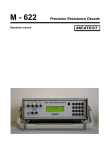
1
OCM622_GB_2904
Precision Resistance Decade
OCM-622
Owner’s Manual
ORBIT CONTROLS AG
CH-8952 Schlieren ZH
www.orbitcontrols.ch
Tel: +41 44 730 2753
INDEX
1.
RESISTANCE DECADE OCM622 .............................................................................................3
2.
CONTENTS OF DELIVERY.......................................................................................................3
3.
SPECIFICATIONS .......................................................................................................................3
4.
PREPARING FOR OPERATION ...............................................................................................6
4.1
4.2
5
SWITCHING-ON .......................................................................................................................6
WARM-UP TIME ......................................................................................................................6
DESCRIPTION .............................................................................................................................7
5.1
FRONTPANEL...........................................................................................................................7
Keyboard ........................................................................................................................................7
Display ............................................................................................................................................7
Output Terminals...........................................................................................................................8
5.2
REAR PANEL ...........................................................................................................................9
6
OPERATION .................................................................................................................................9
6.1
SWITCHING ON AND OFF .......................................................................................................9
6.2
STANDARD MODE – CURSOR MODE .....................................................................................10
6.3
STANDARD MODE – NUMERICAL KEYS ................................................................................10
6.4
DIRECT ENTRY .....................................................................................................................10
6.5
SET UP MODE .......................................................................................................................11
Function........................................................................................................................................11
T. unit (Temperature Units) .......................................................................................................12
Volume..........................................................................................................................................12
Baud rate (RS232 baud rate or address of the IEEE488) ....................................................12
Lightning .......................................................................................................................................12
6.6
CALIBRATION MODE .............................................................................................................13
7
VERIFICATION .........................................................................................................................15
8
REMOTE CONTROL ................................................................................................................16
8.1 COMMUNICATION AND SYNTAXES.................................................................................................16
8.2 COMMANDS ..................................................................................................................................17
8.3 REMOTE CONTROL VIA RS232 .....................................................................................................20
8.4 REMOTE CONTROL VIA IEEE 488 (OPTION) .................................................................................20
8.5 DEMO PROGRAM ..........................................................................................................................21
Date: 11.2003
2
1. Resistance Decade OCM622
The resistance decade OCM622 has been designed for generation of very
accurate resistance values, for calibration of measuring instruments, transmitters and
thermometers. It can also be used in automatic calibration setups in which the
communication data ports RS232 or GPIB IEEE 488 are required.
The resistance value selected with the keyboard or through the data port is
composed by 34 internal resistors optimally connected in parallel and/or serial by the
internal microcontroller. The connection is made by using precision relay with
extremely low thermal voltage. The used resistors are artificially aged foil resistors
with extremely low temperature coefficient.
OCM622 features with very high accuracy and stability, easy control and
mains independent battery operation. The instrument can be controlled from the front
keyboard or remotely via RS232 or IEEE 488 data ports.
2. Contents of Delivery
RS232 version
IEEE488 version
Resistance decade OCM622-V1xxx
Power line adapter
Cable RS-232
Demo program
User’s manual
Test report
Resistance decade OCM622-V2xxx
Power line adapter
Demo program
User’s manual
Test report
3. Specifications
The bellow specifications are valid for functions, ranges with stated relative or
absolute accuracy or specified limits.
Resistance range
:
Pt temperature simulation
Ni temperature simulation
Type of temp. sensors
Resolution
:
:
:
:
1.000 00 Ω - 1 200 000 Ω
SHORT, OPEN terminals
(Version OCM622-Vx1xx only)
-200.000 °C … 850.000 °C (-328 °F … 1562 °F)
-60.000 °C … 300.000 °C (-76 °F … 572 °F)
Pt10 … Pt20000, Ni10 … Ni20000
0.000 01 Ω for 1.000 00 … 10.000 00 Ω
0.000 1 Ω for 10.0001 … 100.000 0 Ω
0.001 Ω for 100.001 … 400.000 Ω
0.01 Ω for 400.01 … 1 200.00 Ω
0.1 Ω for 1200.1 … 30 000.0 Ω
1 Ω for 30000 … 1 200 000 Ω
0.001 °C for Pt10 … Pt300, Ni10 … Ni300
0.01 °C for Pt301 … Pt10000, Ni301…Ni 10000
3
Pt temperature standards
Ni temperature standards
Temperature coefficient
Maximal dissipation power
Maximal voltage
Connection of terminals
Connection of temp. sensors
Reaction time *
Terminals
Interface
Power supply
Operating time from battery
Reference temperature
Working temperature
Storing temperature
Housing
Dimensions (table version)
Dimensions (19” module)
Weight
: IEC 751 (1, 3850 for IPTS68)
IEC 751 (1, 3851 for ITS90)
US (US/JIS) (1, 3916)
: DIN 43760 (6180)
: < 1 ppm/ °C (1 Ω - 2kΩ) on terminals R4W
< 1 ppm/ °C (100 Ω - 1200 kΩ) terminals R2W
< 5 ppm/ °C (2 kΩ - 10 kΩ) on terminals R4W
: 0,3 W
: 50 V DC, 50 Vef AC on terminals R4W
120 V DC, 50 Vef AC on terminals R2W
: 2, 4 wire
: 2, 3 or 4 wire
: 6 ms
: instrument terminals diameter 4mm, gold plated
: RS232 as standard (IEEE488 optionally)
: internal battery 12 V type LONG B-WP 1.9-12
power line adapter 15 V/2A (100 – 240 V)
: 6 hours
: +18 °C … +28 °C
: +5 °C … +40 °C
: -10 °C … +50 °C
: ALU
: W 325 mm, H 111 mm, D 316 mm
: W 483 mm, H 111 mm, D 316 mm
: 4.5 kg
Isolation between output terminals and housing: > 2 GΩ (at 500V DC)
Test voltage between output terminals and housing: 1 kV AC / 50 Hz
* Reaction time is the time between the setting of the value at the front panel or the
reception of the command from the data bus and the resistance value generated at
the output terminals.
Note:
• The data shown with tolerances or with the band of limits are tested. All other
values have informative character.
•
The output terminals may be opened for approx. 1ms during the switching time of
the relays.
4
Accuracy
The specified accuracy is valid after 10 minutes warm up for an ambient
temperature of 23 ± 5 °C. The uncertainties include long-term stability, temperature
coefficient, linearity, load and line regulation and traceability of the manufacturer’s
standards to the National Calibration Standards. Accuracies assigned in % are
related to the set value. Specified accuracy is valid for one year.
Resistance Accuracy - R4W
Range
Accuracy
1 Ω - 400 Ω
0.003 % + 3 mΩ
400 Ω - 2000 Ω
0.005 %
2000 Ω - 10000 Ω
0.015 %
Maximal thermo voltage at theR4W terminals is < 1 µV
Resistance accuracy - R2W
Range
Accuracy
1 Ω - 2000 Ω
0.005 % + 10 mΩ
2 kΩ - 200 kΩ
0.005 %
200 kΩ - 1200 kΩ
0.01 %
Max. thermo voltage at the R2W terminals is < 5 µV for values 1 Ω to 2 kΩ. For 2 kΩ to 1.2 MΩ is < 15
µV.
Pt-Simulation Accuracy
Range
Pt 100 -R4W
Pt 200-R4W
Pt 500-R4W
Pt 1000-R4W
Pt 10000-R4W
-200 … 200 °C
0.02 °C
0.02 °C
0.02 °C
0.04 °C
0.04 °C
200 … 500 °C
0.03 °C
0.04 °C
0.06 °C
0.1 °C
0.06 °C
500 … 850 °C
0.04 °C
0.06 °C
0.15 °C
0.2 °C
0.1 °C
Ni-Simulation Accuracy
Range
Ni 100-R4W
Ni 1000-R4W
Ni 10000-R2W
-60 … 300 °C
0.02 °C
0.04 °C
0.04 °C
Short and Open simulation (version OCM622-Vx1xx only)
When function SHORT is selected, the output resistance is lower than 100 mΩ
(typically 50 mΩ). Maximal allowed current is 500 mA.
When function OPEN is selected, the output resistance is higher than 1 GΩ. Maximal
allowed voltages are 50 V rms with terminals R4W and 120 V DC, 50 Vrms with
terminals R2W.
Note:
The resistance values in range 1 Ω - 1.2 MΩ are calibrated absolutely. The
resistance value is not defined against SHORT position. The functions
SHORT and OPEN are intended for functional checking of tested equipment
only
5
4.
Preparing for operation
OCM-622 Resistance Decade is supplied from the internal battery or from the
external mains adapter, ranging from 100 V to 240 V 50/60 Hz.
The OCM-622 is laboratory device. Its accuracy is guaranteed in a temperature
range 23 ± 5 °C. The instrument is designed for use in a horizontal or in a slope
position. The angle of slope is determined by the handle.
After unpacking let the instrument stabilized for one hour at the specified
temperature.
4.1 Switching-on
If the instrument is supplied from internal battery only, push the button POWER.
If power line adapter is connected, decade will switch on automatically. After
switching on internal tests are performed for approx. 3sec. The display shows the
type of the instrument and the manufacturer. The display switches into the last used
mode before the power has been switched-off. The factory setting is 100Ω.
4.2 Warm-up Time
The instrument operates immediately after switching on. After a 10 min. warmup period it meets the specified accuracy.
6
5 Description
5.1 Frontpanel
Keyboard
The key MENU opens the setting and the calibration menu.
The key BSP cancels the latest entry.
The key ESC cancels the whole entry and/or closes the menu.
The key ENTER confirms the entry. The same key switches between the numerical
keys (black print) and the cursor function (blue print). The cursor function is shown at
the display with ↑ .
The key POWER switches the power ON and OFF. To switch off, the key has to be
pressed twice.
Display
The alphanumerical Display shows the operation parameters. The upper line shows
the main function, the lower line shows the auxiliary parameters. The right down
corner displays following functions:
- Cursor Keys – blue print at the keys.
- Remote operation via RS232 or IEEE488 (REMOTE)
- Battery has to be charged
- Charger in operation
7
Output Terminals
The output resistance is available in four (R4W) or two (R2W) connections. The
upper four terminals R4W permits 2 and 4 wire connection in the resistance mode of
operation, and 2, 3 or 4 wire connection when the decade is used as Pt/Ni
temperature simulator. The range of setting is 1 Ω to 10 kΩ. The max. resistance
value is determined by the selection of the type of the output terminals 4W or 2W.
The two wire connection R2W permits the settings from 1 Ω to 1.2 MΩ.
The terminals are automatically switched between R2W and R4W in
accordance with the set resistance value. Low resistance values are connected
always to R4W terminals. The switching level between R4W and R2W is
programmable from 0 Ω to 10 kΩ in the MENU parameter 4W < 2W. Recommended
4W < 2W value is 2000Ω.
Active terminals are indicated with LED at the front panel.
The terminal “GROUND” is connected with the cabinet.
8
5.2 Rear Panel
The rear panel contains the charger jack and the data bus connector.
6 Operation
6.1 Switching ON and OFF
The instrument is always ON when the charger is connected to the mains.
When powered from internal battery, the instrument has to be switched-on with the
POWER key. To switch-off, press the POER key twice. The instrument switches-off
automatically when during 20 minutes no key is operated. One minute before the
power is switched-off, a beep tone sounds. Low battery is indicated by
symbol at
the display.
9
6.2 Standard Mode – Cursor Mode
When switched-on, the standard mode is activated and the display shows:
The upper row shows the simulated temperature [°C] or the generated resistance [Ω].
The lower row shows the temperature scale IPTS68, ITS90 according to the IEC751
or US JIS standards. The arrow symbol informs about the activated cursor function of
keys 2, 4, 6, 8 (blue prints). With the keys ↑ ↓ the selected position can be
incremented or decremented. With the keys ← → the cursor can be moved left or
right. The key ENTER switches between the cursor and numerical type of entry.
When the key MENU is pressed, the SET UP function is activated.
6.3 Standard Mode – Numerical Keys
The upper row shows the simulated temperature [°C] or the generated
resistance [Ω]. The value can be directly overwritten with the keyboard and confirmed
with ENTER. The key ENTER switches between the numerical and the cursor entry.
The lower row shows the sensor type at the temperature simulation (Pt-100, Ni
1000 etc.). The corresponding norm is shown when the Pt elements are selected
US/JIS for the US-Norm, IPTS68 or ITS90 for the european norm IEC 751.
With the key MENU the setting mode is activated.
6.4 Direct Entry
With numerical keys the temperature value (or resistance) can be directly
entered. The recently entered value is displayed in brackets under the actually value.
Press the key ENTER to confirm the setting. The key ESC terminates the entry. The
key BSP cancels the last entered value.
10
6.5 Set Up Mode
This mode permits setting and displaying of some auxiliary parameters. To
enter this mode, push the key MENU in the standard mode. With the cursor keys ↑ ↓
following items can be displayed in the setup menu:
Function
With the keys ← → following functions can be activated:
R
- Resistance. Range 1.00000 Ω to 1200000Ω.
Pt (68) - Pt thermometer according to IEC 751 (Temp. Scale IPTS68,
coeff.1,3850).
Range: -200 °C to 850 °C (-328 °F to 1562 °F). The zero value R0
(resistor value @ 0°C) can be set from 10 Ω to 20 000Ω.
Pt (90) - Pt-thermometer according to IEC 751 (Temp. Scale IPTS 90, coeff.
1,3851). Range: -200 °C to 850 °C (-328 °F to 1562 °F). The zero value
R0 (Resistor value @ 0°C) can be set from 10 Ω to 20 000 Ω.
Pt (US) - Pt thermometer according to US-Norm US/JIS, coeff. 1,3916. Range: 200 °C to 850 °C (-328 °F to 1562 °F). The zero value R0 (Resistor value
@ 0°C) can be set from 10 Ω to 20 000 Ω.
Ni
- Nickel thermometer according to DIN 43760, coeff. 6180. Range: -60 °C
to 300 °C (-76 °F to 572 °F). The zero value R0 (Resistor value @ 0°C)
can be set from 10 Ω to 20 000 Ω.
User
- Used defined range and curve. Standard is NTC Thermometer with
following polynom installed:
R(T) = 330*exp (-4050*((1/298,15)-(1/(T+273,15))))
Range: -30 °C to 110 °C.
Short
- simulates short of the output terminals. Function Short is Option.
Open
- simulates open of the output terminals. Function Open is Option.
The positions appear at the lower line. After ENTER they appear in the upper line.
R0 (Pt,Ni) (Resistance at 0°C)
The parameter R0 for temperature sensors can be set. The value R0 is valid for both
Pt and Ni sensors. A new value can be entered with the keyboard. The permitted
range is from 10 Ω to 20 000 Ω. The new value is stored with ENTER.
4W < 2W (the highest resistance value on R4W terminals)
This function permits settings of the resistance value when the output terminals
switch from R4W to R2W. Resistance values higher than 10 000 Ω are available only
on terminals R2W. Lower values than 10 000 Ω are available at the R4W terminals.
At the R2W terminals is the resistance also available but with lower accuracy. The
range of setting is 10 to 10000 Ω.
11
T. unit (Temperature Units)
With the keys ← → °C or °F can be selected. The key ENTER memorizes the
selection.
Volume
With the keys ← → the beeper intensity of the keyboard can be adjusted. The
selection is from 0 to 15. The key ENTER memorizes the selection.
Baud rate (RS232 baud rate or address of the IEEE488)
Instruments with RS232 can have the baud rate selected with the keys ← → for
300, 600, 1200, 2400, 4800, 9600 or 19200 bd.
Instruments with IEEE488 data port can select the address from 0 to 30. The key
ENTER memorizes the selection
Lightning
The display backlight can be switched on or off. With the keys ← → OFF (lightning
is switched off), 30 s (lightning is switched on for 30 sec. after last key entry), 5m
(lightning is switched on for 5 minutes after the last key entry) or ON (lightning is
switched on). The selected parameter is displayed in the lower row. The key ENTER
memorizes the selection. If the instrument is supplied from the external power
adapter, the lightning is switched on all the time.
Note: The display backlight influences significantly the operating time of the internal
battery. When the backlight is not used, the battery operation time is about 50%
longer.
Calibration mode, password setting
The calibration password is a five digit number, which must be entered to access the
calibration mode. The factory setting is “00000”. It is recommended to change the
password and note it. Without the password the calibration can not be performed.
The Password can be changed and the new password can be entered directly from
keyboard. Enter 00000 and the new password. Confirm with ENTER.
Serial number
The serial number of the instrument is entered during the production and can not be
alternate.
12
6.6 Calibration Mode
The precision resistors of the decade can be recalibrated. The access to the
calibration mode is permitted after double pressing of the key MENU from the
standard mode or after single pressing from the SETUP mode.
The correct password must be entered before calibration. Without correct
password the access to the calibration mode is refused. Default factory set calibration
code is “00000”. Return to standard mode with the key ESC.
Recalibration procedure contains precision measurements of 36 basic resistors
and entering their new values into the memory. The keys ↑ ↓ can be used for the
settings.
Following table shows the nominal values during the calibration and the
required recalibration accuracy:
Etalon (Terminals)
Nominal
value
Calibration
accuracy
Etalon
(Terminals)
Nominal
value
Calibration
accuracy
R00 (R 4W)
R01 (R 4W)
R02 (R 4W)
R03 (R 4W)
R04 (R 4W)
R05 (R 4W)
R06 (R 4W)
R07 (R 4W)
R08 (R 4W)
R09 (R 4W)
R10 (R 4W)
R11 (R 4W)
R12 (R 4W)
R13 (R 4W)
R14 (R 4W)
R15 (R 4W)
R16 (R 4W)
R17 (R 4W)
2,0 Ω
3,9 Ω
7,8 Ω
15,4 Ω
30,5 Ω
60,5 Ω
120 Ω
237 Ω
464 Ω
909 Ω
1780 Ω
3480 Ω
6870 Ω
13,5 kΩ
26,6 kΩ
52,2 kΩ
103 kΩ
202 kΩ
1 mΩ
1 mΩ
1 mΩ
1 mΩ
1 mΩ
1 mΩ
2 mΩ
3 mΩ
6 mΩ
15 mΩ
30 mΩ
100 mΩ
250 mΩ
500 mΩ
1Ω
5Ω
10 Ω
20 Ω
R18 (R 4W)
R19 (R 4W)
R20 (R 4W)
R21 (R 4W)
R22 (R 4W)
R23 (R 4W)
R24 (R 4W)
R25 (R 4W)
R26 (R 4W)
R27 (R 2W4W)
R28 (R 2W4W)
R29 (R 2W4W)
R30 (R 2W4W)
R31 (R 2W4W)
R32 (R 2W4W)
R33 (R 2W4W)
R34 (R 2W4W)
R35 (R 2W4W)
398 kΩ
780 kΩ
1540 kΩ
3020 kΩ
5920 kΩ
12 MΩ
23 MΩ
46 MΩ
85 MΩ
1780 Ω
3830 Ω
7870 Ω
15,8 kΩ
34 kΩ
75 kΩ
150 kΩ
301 kΩ
602 kΩ
40 Ω
80 Ω
200 Ω
400 Ω
1 kΩ
5 kΩ
50 kΩ
200 kΩ
500 kΩ
40 mΩ
80 mΩ
100 mΩ
200 mΩ
500 mΩ
1Ω
4Ω
10 Ω
20 Ω
13
The process of calibration contains the measurement of the single resistors and
writing their values into the memory. The Etalon is selected with ↑ ↓.
•
•
•
Measure the resistance with four wire method.
Activate the keyboard with ENTER.
Enter the new value. The first line shows the original value, the lower line
the new value.
•
•
Press ENTER to memorize the new entry.
Repeat for all Etalons.
Recommended schematic for R00 to R26 (Terminals R4W)
Recommended schematic for R27 to R35 (Terminals R2W)
14
7 Verification
The verification procedure is described in this chapter. It is based on resistance
measurement on the output terminals with standard multimeter in recommended
points.
Required equippment
• Ohm-meter with accuracy of 0.001%, ranging frrom 1 Ω to 1.2 MΩ (e.g. Wavetek
1281).
Instrument Setting
Switch into the resistance mode. Connect the multimeter with 4 cables to the output
terminals.
Measuring Steps
• output resistance on terminals R4W
• output resistance on terminals R2W
Procedure
Use the following procedure to perform the parameter verification test.
1. Switch both instruments on and let them for 1 hour stabilise in the laboratory
ambient temperature 23±2 °C. Connect the terminals R4W to the ohm-meter. Set
value 4W<2W to 10 kOhm in the SETUP menu.
2. Check resistance values as shown in table I.
Table : Max. Deviation on terminals R 4W
Nom. Value [Ω]
1.00000
2.00000
5.00000
10.00000
20.0000
50.000
100.000
200.00
500.00
1000.0
2000.0
5000.0
10000.0
Max. deviation [mΩ]
3.03
3.06
3.15
3.3
3.6
4.5
6.0
9.0
25
50
100
750
1500
15
3. Connect the ohm-meter to R2W terminals. Use four-wire connection to 10 kOhm.
Above 10k two or four wire connection can be used. Set function 4W<2W to 0 Ω
in the SETUP menu.
4. Check the resistance value in points according to Table II.
Table II. Maximal deviation on terminals R 2W
Value [Ω]
1.00000
10.00000
100.000
1000.0
2000.0
5000.0
10000.0
20000.0
50000
100000
200000
500000
1000000
1200000
8
Max. deviation [Ω]
0.01
0.011
0.015
0.060
0.1
0.25
0.5
1.0
2.5
5.0
20
50
100
120
Remote Control
The standard version is equipped with RS232 data port. The IEEE488 data port
is described under 8.4. The commands for both versions are the same.
8.1 Communication and Syntaxes
The communication between the instrument and the PC consists of flow of
periodically alternating commands type command-response or query-response. The
command is always a letter followed by parameter and ended by control sign <cr> or
<lf>. The response is always ended with <cr> <lf>.
16
Syntax description
<DNPD> = Decimal Numeric Program Data. This format is used to express decimal
number with or without the exponent.
<CPD> = Character Program Data. Usually represent a group of alternative
character parameters, e.g. {0 | 1 | 2 | 3}.
?=
Flag indicating a request for the value of the parameter specified by the
command. No other parameters than the question mark can be used.
(?) =
Flag indicating a request for the parameter specified by the command.
This command permits a value to be set as well as requested.
<cr> =
carriage return. ASCII code 13. This code executes the program line.
<lf> =
line feed. ASCII code 10. This code executes the program line.
8.2 Commands
Value setting / reading
A (?) <DNPD>
This command sets the resistance or the temperature values.
<DNPD>
It represents the resistance value in Ohm or simulated temperature in °C. The
parameters of temperature can be set with negative or positive sign. The resistance
parameters can be set only with positive sign only.
In the Control Mode, the instrument confirms the correct setting with „Ok <cr><lf>”.
In case of query, OCM-622 returns the resistance/temperature values in the same
format as it is on the display, e.g. -120 °C is returned as -120.000 <cr><lf>. Positive
numbers are sent without the polarity sign.
Example:
If OCM-622 is in the temperature simulation function, the command „A123.564 <cr>”
sets the temperature to 123.564 °C. In the resistance mode the value of 123.564 Ω is
at the output terminals.
If query „A?<cr>” is sent, OCM-622 responds „123.564<cr><lf>”.
Setting of functions
F <CPD> { 0 | 1 | 2 | 3 | 4 | 5 | S | O }
Following functions can be set:
• 0
resistance mode
• 1
Pt (68) temperature sensor simulation
• 2
Pt (90) temperature sensor simulation
• 3
Pt (US) temperature sensor simulation
• 4
Ni temperature sensor simulation
• 5
User temperature sensor simulation
• S
Short simulation (extra ordered option)
• O
Open simulation (extra ordered option)
OCM-622 confirms „Ok <cr><lf>”.
Example:
„F1<cr>” sets Pt100 sensor simulation.
17
Switching off
P0
This command will switch off the instrument. The command is executed if OCM6-22
is supplied from internal battery only, without the external battery charger. Correct
execution is confirmed with string „Ok <cr><lf>”.
Example:
„P0<cr>” switches decade off.
R0 setting / reading
R (?) <DNPD>
This command sets the resistance value R0 at the temperature 0 °C. The value R0 is
valid for all types of simulated temperature sensors.
<DNPD>
It represents resistance value R0 in Ω. The limits are shown in chapter
„Specifications“. OCM-622 confirms the execution with a string „Ok <cr><lf>”. In case
of query OCM-622 returns the value in Ω.
Example:
„R100 <cr>” sets R0 to 100 Ω (Pt100, Ni100).
After query „R? <cr>” OCM-622 returns „100<cr><lf>”.
Temperature unit setting
U <CPD> {0 | 1}
This command sets the temperature units:
• 0
degree Celsius °C
• 1
degree Fahrenheit °F
OCM-622 confirms with „Ok <cr><lf>”.
Example:
„U0<cr>” sets °C.
Status reading
V?
OCM-622 returns the status in form „FxUx <cr><lf>“. „x“ are values corresponding to
the actual status of the instrument.
Example:
After query „V?<cr>” OCM-622 returns for example string „F2U0<cr><lf>”, which
means Pt (90), °C actual setting.
18
Setting of the resistance value for switching the terminals 2W/4W
W (?) <DNPD>
This command sets value of the resistance for switching the output terminals from
R4W to R2W and return.
<DNPD>
This represents the resistance value in Ω. The limits are shown in chapter
“Specifications”. OCM-622 confirms the execution with string „Ok <cr><lf>”. In case of
query OCM-622 returns the value in Ω.
Example:
„W2000 <cr>” sets value to 2000 Ω.
After query „W?<cr>” the instrument returns a string „2000<cr><lf>”.
I/D (device identification)
*IDN?
The response contains the name of the manufacturer, the model, the serial number
and the firmware version.
Example:
If query „*IDN?<cr>” OCM-622 returns:
„ORBIT,M622,462351,2.4 <cr><lf>“.
When unknown command is received, OCM-622 returns "? <cr><lf>“. Correctly
executed command is confirmed with "Ok <cr><lf>. When a correct query is received,
OCM-622 responds in the above described form. All commands must be terminated
with <cr> or <lf>. Small and capital letters are allowed.
19
8.3 Remote Control via RS232
The transmission baud rate can be selected from 300 to 19200 Bd. The
telegram contains 8 bit, no parity, 1 Stop. For the data flow the hardware handshake
(RTS/CTS) and the program handshake (XON/XOFF) are switched-off. The RS 232
is isolated.
RS-232 connection
Pin
Text
Type
Description
2
3
5
TXD
RXD
GND
Output
Input
-
Sender
Receiver
GND
Connector type: D-SUB 9, MALE
Cable between OCM622 and PC (configuration 1:1)
PC
D-Sub 1 D-Sub 2
2
2
Sender
3
3
Receiver
5
5
GND
Receiver
Sender
GND
OCM-622
8.4 Remote Control via IEEE 488 (Option)
IEEE488 contains following functions:
SH1, AH1, T5, L3, RL1, DC1
The instrument recognizes following commands:
DCL Device Clear – sets the instrument into the basic
function.
SDC Selected Device Clear – same as DCL.
GTL Go to Local – terminates the remote control.
LLO Local Lock Out – switches-off the keyboard.
The IEEE488 commands are identical with the RS232
commands.
20
8.5 Demo Program
A simple program is supplied with OCM-622 which supports the control via the
data ports RS232 and IEEE 488. The installation diskette contains the program for
WIN95/98/ME/NT/2000/XP. For IEEE488 the Demo Program requires properly
configured National Instruments IEEE488 card.
Installing the program
After SETUP.EXE, the installation program asks for the destination directory (predefined is R Decade) and executes the actual installation. The UNINST.EXE program
is also enclosed for deleting the directory from the system.
Program description
After starting the program “R decade”, following control panel is displayed:
In „Communication“select RS232 or IEEE488. Set the COM and the baud rate. When
the IEEE488 is used, set the address. Start the program with “Open”. The program
checks if the instruments is connected. If the instrument is found, it can be controlled
from the PC. Use „Output“ to enter the required value or select it with the arrows up
or down by using the mouse.
Press “Exit” to terminate the program.
21
9. 19“ Rack
OCM-622 can also be ordered for 19“ rack mount.
10. Electric Function
The internal resistors are switched in a binary code by using precision relays
with very low thermal voltage. The resistors are artificially aged and for high accuracy
of the Tempco selected. The LED at the front shows that the selected resistor value
is connected to the terminals. The metal cabinet is connected to the mains GND.
The 16 bit controller permits the settings and the selection of the mode via the
keyboard or the data ports. It supports also the display showing the parameters and
the output values. The electronics is supplied from internal battery. A line battery
charger is enclosed.
11. Mechanical Construction
The instrument is enclosed in aluminium cabinet. The keyboard, the display
and the output terminals are located on the front panel. External power supply jack
and RS-232 connector are located on the rear panel. Internal battery is fixed to the
rear panel inside the cabinet.
11.1 Battery maintenance
The sealed lead-acid maintenance-free long-life 12V, 2.6Ah battery requires
approx. 40 hours for full charge. It also has to be charged when the instrument is not
in use for longer than 3 month.
To replace the battery, use following steps:
• Disconnect the external power supply adapter and RS-232 (IEEE488) cable.
• Switch off the instrument.
• Take out the 4 screws located in the corners of the rear panel.
• Remove the top cover.
• Disconnect connectors and release the battery.
• Replace the battery with the same type.
• Close the cabinet the opposite way as it has been opened.
22
12. Ordering Information
Data Output
OCM622-V1xxx
RS232
OCM622-V2xxx
IEEE 488
Additional Options
OCM622-Vx0xx
none
OCM622-Vx1xx
Short/Open Function
Cabinet
OCM622-Vxx0x
table version
OCM622-Vxx1x
19“ Rack version
ORBIT CONTROLS AG
CH-8952 Schlieren ZH
www.orbitcontrols.ch
Tel: +41 44 730 2753
23