1
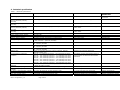
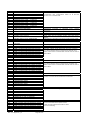
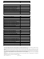
Local fire relay contact rating
First stage contact rating
Second stage contact rating
Extract contact rating
Zone quiescent current
Terminal capacity
Number of detectors per zone
Number of sounders per circuit
Detection circuit end of line
Monitored input end of line
Sounder circuit end of line
Extinguishant output end of line
No. of detection circuits
No. of sounder circuits
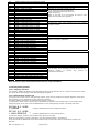
5 to 30VDC 1A Amp maximum for each
5 to 30VDC 1A Amp maximum for each
5 to 30VDC 1A Amp maximum for each
5 to 30VDC 1A Amp maximum for each
0mA minimum, 2mA maximum
0.5mm2 to 2.5mm2 solid or stranded wire
Dependent on type
Dependent on type and current consumption
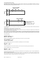
6K8 +/- 5% ½ Watt resistor
6K8 +/- 5% ½ Watt resistor
10K +/- 5% ¼ Watt resistor
1N4004 Diode
Two to eight. 21 VDC
Dependent on model 18 to 30V DC
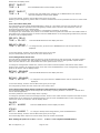
Maximum ratings not to be exceeded
Maximum ratings not to be exceeded
Maximum ratings not to be exceeded
Maximum ratings not to be exceeded
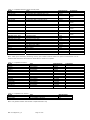
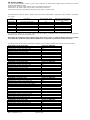
See tables 2 and 3 for detector types
Extinguishant release output
18 to 30V DC. Fused at 1 Amp
Extinguishant release delay
Extinguishant release duration
SIL, AL, FLT, RST inputs
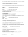
Adjustable 0 to 60 seconds (+/- 10%)
Adjustable 60 to 300 seconds
Switched -ve, min resistance 0 ohms, max resistance 100
Ohms
8K ohm to 1K ohm
1 Amp maximum load –for 5 minutes
3 Amps for 20 milliseconds
5 second steps
5 second steps
Only to be used with Aux ROV terminal
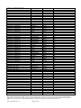
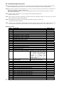
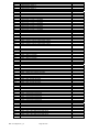
Zone normal threshold (Allowable
EOL)
Detector alarm threshold
Call point alarm threshold
Short circuit threshold
Head removal condition
Cabling
Monitored inputs normal threshold
(Allowable EOL)
Monitored inputs alarm threshold
Monitored inputs Short circuit
threshold
Status unit/Ancillary board
connection
Status unit power output
Man-1112 Sigma XT+_15
999 ohms to 400 ohms
399 ohms to 100 ohms
99 ohms to 0 ohms
15.5 to 17.5 volts
FP200 or equivalent (maximum capacitance 1uF max
inductance 1 mH
10K ohm to 2K ohm
See table 2
See table 4 for sounder types
Supplied in terminals
Supplied in terminals
Supplied in terminals
Supplied in terminals
Dependent on model
2 x on detection section –1st stage and
1 x 2nd stage per exting area.
Volt
Volt
Volt
Volt
free
free
free
free
changeover
changeover
changeover
changeover
contact
contact
contact
contact
2nd stage sounders are outputs
to alarm devices as required by
EN12094-1
Voltage reversing DC with
calibration facility
Switched DC
Use 6K8 end of line resistor
Nominal trigger resistance 470 ohms
Nominal trigger resistance 270 ohms
2-wire detector base or schottky diode
base
Metal cable glands must be used
2K ohms to 150 ohms +/- 5%
140 ohms to 0 ohms +/- 5%
Two wire RS485 connection (EIA-485 specification)
18 to 30V DC, Fused at 500mA with electronic fuse
Page 9 of 50
Maximum of 7 units per area- RS485
data cable.
Compatible status units - K911000M8,
K911000F8, K911100M8, K911100F8,
K911110M8, K911110F8, W911000W8,
W911100W8, W911110W8
250 milliamp maximum load
(EIA-485 specification)
Max 3 per module – More status
units must be supplied with
external power supply