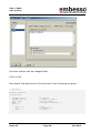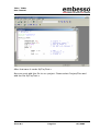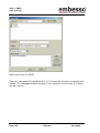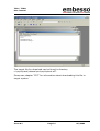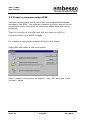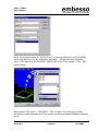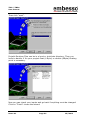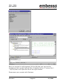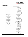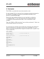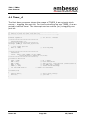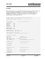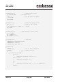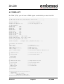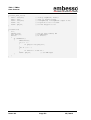
1
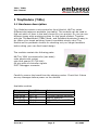
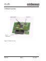
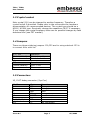
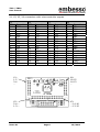
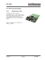
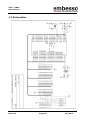
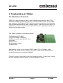
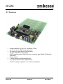
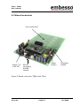
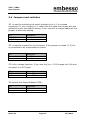
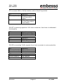
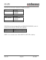
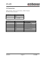
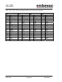
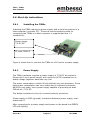
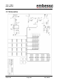
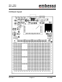
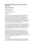
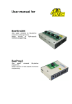
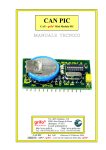
TiMo / TiBBo
User manual
H8-Tiny
TinyModule (TiMo)
TinyBasicBoard (TiBBo)
for Hitachi H8/36XX
User Manual
Issue 0.1
Page 1
05/2002
TiMo / TiBBo
User manual
PREFACE
Product Warranty
The warranty period against defects in materials and workmanship are as set out in the
accompanying Customer Information sheet.
Limitation of Warranty
The foregoing warranty does not cover damage caused by fair wear and tear, abnormal
storage conditions, incorrect use, accidental misuse, neglect, corruption, misapplication,
addition or modification or by the use with other hardware or software, as the case may
be, with witch the product is incompatible. No warranty of fitness for a particular purpose
is offered. The user assumes the entire risk of using the product. Any liability of embesso
GmbH is limited exclusively to the replacement of defective material or workmanship.
Trademarks
All brand or product names used in this manual are trademarks or registered trademarks
of their respective companies or organizations.
Microsoft is a registered trademark and Windows and Windows NT are trademarks of
Microsoft Corporation. IBM is a registered trademark of International Business Machines
Corporation.
Cautions
This document may be, wholly or partially, subject to change without notice. All rights
reserved. No one is permitted to reproduce or duplicate, in any form, a part or this entire
document without embesso GmbH written permission.
Restrictions
Please refer to the restrictions of all components and tool suppliers.
Hardware Considerations
Grounding: This hardware is designed for use with equipment that is fully grounded.
Ensure that all equipment used is appropriately grounded. Failure to do so could lead to
danger for the operator or damage the equipment.
Electrostatic Discharge Precautions: This hardware contains devices that are sensitive to
electrostatic discharge. Ensure appropriate precautions are observed during handling and
accessing connections. Failure to do so could result in damage to the equipment.
Electromagnetic Compatibility: This product can cause radio frequency noise when used
in the residential area. In such cases the user of the equipment my be required to take
appropriate countermeasures under his responsibility.
Support
Support by EMBESSO GmbH is provided only for the supplied hardware. Any software
tools are supported from their supplier. Please notice that maybe some software tools
coming with this kit are only unsupported freeware and no support will be given.
For embesso support please contact: [email protected]
Issue 0.1
Page 2
05/2002
TiMo / TiBBo
User manual
Table of Contents
PREFACE .............................................................................. 2
Table of Contents .................................................................. 3
1 TinyModule (TiMo)............................................................. 5
1.1
Hardware description .................................................. 5
1.2
Board overview.......................................................... 6
1.3
Crystal socket............................................................ 7
1.4
Jumpers.................................................................... 7
1.5
Connectors ................................................................ 7
1.6
Start-Up instructions .................................................. 9
1.7
Schematics................................................................ 10
2 TinyBasicBoard (TiBBo)...................................................... 11
2.1
Hardware Overview .................................................... 11
2.2
Features ................................................................... 12
2.3
Board overview.......................................................... 13
2.4
Jumpers and switches................................................. 14
2.5
Connectors................................................................ 17
2.6
Start-Up instructions .................................................. 19
2.7
Schematics................................................................ 20
2.8
Board layout.............................................................. 21
3 Development Environment ................................................. 22
3.1
Software Tools........................................................... 22
3.2
Create a program using IAR-EWH8............................... 24
3.3
Create a program using HEW....................................... 32
3.4
Download the code using FDT ...................................... 38
3.5
Workflow................................................................... 46
4 Examples ......................................................................... 47
4.1
Timer_A.................................................................... 48
4.2
SCI .......................................................................... 49
4.3
PWM+SCI ................................................................. 51
Appendix A: CD-R content ...................................................... 53
Issue 0.1
Page 3
05/2002
TiMo / TiBBo
User manual
Issue 0.1
Page 4
05/2002
TiMo / TiBBo
User manual
1 TinyModule (TiMo)
1.1 Hardware description
Tiny Modules contain a microcontroller from Hitachi’s H8/Tiny series.
Different derivates are available (see table). The modules can be used to
find out which of them is the best choose for your project. Or you can use
different types while prototyping then for the target product. Together
with the TinyBasicBoard (TiBBo) Hard- and Software developing is easy to
do. When your target periphery board is available simply use a Tiny
Module as the processor module for checking out your target hardware
before doing your own final board design.
The modules contain the following parts:
H8/Tiny 36XX microcontroller (see table)
main quartz with socket
sub clock quartz (32.768 kHz)
64 pins with all controller signals
E10T-Debugger connector
Carefully remove the board from the shipping carton. Check first if there
are any damages before power on the module.
Available modules
Code
Timo3664F
Timo3664N
Timo3672F
Timo3687G
Timo3694G
Issue 0.1
Flash/RAM
32k / 2k
32k / 2k
16k / 2k
56k / 4k
16k / 2k
Options
512 Byte internal EEPROM
without subclock
POR / RTC / 2nd USART
POR
Page 5
05/2002
TiMo / TiBBo
User manual
1.2 Board overview
subclock
main crystal
E10T
connector
Figure 1 Board overview
Issue 0.1
Page 6
05/2002
TiMo / TiBBo
User manual
1.3 Crystal socket
Main crystal (Q1) can be changed to another frequency. Therefore a
crystal socket is provided. Please refer to the microcontroller hardware
documentation for recommended devices. The crystal type should be a
HC49 / HC49U type. Eventually change the capacitors C6/C7 if necessary.
If you change the crystal frequency take care on possible changes by flash
download tool (see FDT manual).
1.4 Jumpers
There are three soldering jumpers. JP1/JP2 are for using subclock. JP3 is
to connect AVcc with Vcc.
JP1 / JP2
Closed (default)
Open
Operation
Subclock enable
Subclock disable
JP3
Closed (default)
Open
Operation
AVcc = Vcc
AVcc = open
1.5 Connectors
X5, E10T debug connector (Sys-Con)
X1, Pin
1
5
7
11
13
8
2,4,6,10,12,14
3,9
Issue 0.1
µC-pin
P87
P86
/NMI
P85
/RESET
Vcc
GND
n.c.
Operation
Debug pin
Debug pin
/NMI
Debug pin
reset control
Not connected
Page 7
05/2002
TiMo / TiBBo
User manual
X1, X2, X3, X4 connectors with microcontroller signals
X1
PIN
1
2
3
4
5
6
7
8
9
10
11
12
13
14
15
16
Operation
GND
n.c.
n.c.
VCC
P50
P51
P34
P35
P36
P37
P52
P53
P54
P55
P10
P11
X2
PIN
1
2
3
4
5
6
7
8
9
10
11
12
13
14
15
16
Operation
P12
P56
P57
P74
P75
P76
P24
P63
P62
P61
/NMI
P60
P64
P65
P66
P67
X3
PIN
1
2
3
3
5
6
7
8
9
10
11
12
13
14
15
16
Operation
P85
P86
P87
P20
P21
P22
P23
P70
P71
P72
P14
P15
P16
P17
P33
P32
X4
PIN
1
2
3
4
5
6
7
8
9
10
11
12
13
14
15
16
Operation
P31
P30
PB3
PB2
PB1
PB0
PB4
PB5
PB6
PB7
AVCC
n.c.
n.c.
VCL
/RES
GND
X1:
1-2
3-4
…
X4:
16-15
14-13
…
X2:
2-4-…
1-3-…
X3:
…-14-16
…-13-15
Issue 0.1
Page 8
05/2002
TiMo / TiBBo
User manual
1.6 Start-Up instructions
1.6.1
Installing the TiMo
Installing the TiMo requires a
TinyBasicBoard or a user target board.
Power down target board and put in the
Tiny module. Check if all pins are
connected! Then power up the target
board.
Figure 2 shows how to connect the
TiMo to a TiBBo
Issue 0.1
Page 9
05/2002
TiMo / TiBBo
User manual
1.7 Schematics
Issue 0.1
Page 10
05/2002
TiMo / TiBBo
User manual
2 TinyBasicBoard (TiBBo)
2.1 Hardware Overview
TiBBo is a basic board for Hard- and Software development with Tiny
modules containing Hitachi’s H8/Tiny microcontroller series. It can take
one embesso TinyModule (TiMo) and provides development functionality
like software download to flash, power supply, reset circuit and more. In
addition it contains a great wire wrap field for user applicable periphery
while development phase.
The TiBBo contains the following parts:
TinyBasicBoard (TiBBO)
+5V/3V3 voltage regulator
SubD9 connector and RS232 level
converter
Reset button
Run/Program switch
4 plastic feet
Additionally there is a kit with a RS232 cable (1.8m, DSub9, malefemale), an AC/DC Power Supply and a CD-R with some development
tools and software examples available.
Carefully remove the board from the shipping carton. Check first if there
are any damages before power on the evaluation board.
Issue 0.1
Page 11
05/2002
TiMo / TiBBo
User manual
2.2 Features
socket adapter for H8/Tiny Modules (TiMo)
In-Circuit serial Flash programming
All resources available for evaluation
All pins routed to connectors
UART interface with MAX232 level converter and SubD-9 (female)
connector
• Reset button
• 1 switch user/prog(programming)
• wire wrap field for user applications
• 5V/3V3 voltage regulator on board (switchable)
•
•
•
•
•
Issue 0.1
Page 12
05/2002
TiMo / TiBBo
User manual
2.3 Board overview
wire wrap field
Power 7,5
V-9V DC
Reset
button
RS232
connector
SubD9
female
Prog/Run
switch
Figure 3 Board overview (TiBBo with TiMo)
Issue 0.1
Page 13
05/2002
TiMo / TiBBo
User manual
2.4 Jumpers and switches
JP1 is used for switching the serial interface from 1:1 to crossed
connection. If you connect a 1:1 cable (like the cable that comes with the
optional kit) use the default setting. If you connect a crossed cable set the
jumper to alternate setting.
JP1
1-3, 2-4
1-2, 3-4
Operation
1:1 operation
Crossed connection
JP2 is used to connect Vcc to the board. If the jumper is closed (1-2) Vcc
is connected to all components on board.
JP2
Closed (default)
Open
Operation
Vcc ON
Vcc Off
JP3 is for voltage selection. If you use the Vcc = 3V3 change the V24 level
converter to a 3V3 type!
JP3
1-2
2-3
Operation
Vcc = 5V
Vcc = 3V3
JP4 selects the PowerOnReset (POR).
JP4
Closed (default)
Open
Issue 0.1
Operation
POR on board
POR open
Page 14
05/2002
TiMo / TiBBo
User manual
JP5 connects NMI to PullUp resistor and to Run/Prog switch
JP5
Closed (default)
Open
Operation
NMI pulled up
Run/Prog switch
enable
NMI is open
No Run/Prog switch
functionality
JP6/JP7 containing signals to V24 level converter. Use them in dedicated
functionality
JP6
1
2
Operation
T2 Output to V24
R2 Input from V24
JP7
1
2
Operation
T2 Tx-Input
R2 Rx-Output
JP8/JP9 connecting Tx/Rx signals from level converter to microcontroller.
JP8
Closed (default)
Open
Operation
TxD enabled
TxD disabled
JP9
Closed (default)
Open
Operation
RxD enabled
RxD disabled
Issue 0.1
Page 15
05/2002
TiMo / TiBBo
User manual
JP10/JP11 are for direct connects on SubD9 connector.
JP10
Closed (default)
Operation
X1.4(DTR) and
X1.6(DSR)
connected
Open
JP11
Closed (default)
Operation
X1.7(RTS) and
X1.8(CTS)
connected
Open
PROG/RUN switches between RUN- and PROG(PROGRAMMING) mode. In
programming mode the YELLOW LED is lighting.
Orientation
LEFT
RIGHT
Operation
PROG(programming) mode
RUN mode
RESET is for controller reset. While RESET the RED LED is lighting.
Issue 0.1
Page 16
05/2002
TiMo / TiBBo
User manual
2.5 Connectors
SubD_Female, Serial communication, SubD-9 female
PS-CON, Power connector
PS-CON, Pin
1
2
Operation
GND
DC power supply,
7,5 – 9 VDC
SubD9, Pin
1
2
3
4
5
6
7
8
9
Operation
n.c.
TXD
RXD
DTR
GND
DSR
RTS
CTS
n.c.
Issue 0.1
Remark
Not connected
Connected to JP8
Connected to JP9
Connected to JP10
Connected to JP10
Connected to JP11
Connected to JP11
Not connected
Page 17
05/2002
TiMo / TiBBo
User manual
SV1, SV2, SV3, SV4 connectors with microcontroller signals
SV1
PIN
1
2
3
4
5
6
7
8
9
10
11
12
13
14
15
16
Operation
PB6
PB7
AVCC
X2
X1
VCL
/RES
TEST(GND)
GND
OSC2
OSC2
VCC
P50
P51
P34
P35
Issue 0.1
SV2
PIN
1
2
3
4
5
6
7
8
9
10
11
12
13
14
15
16
Operation
P36
P37
P52
P53
P54
P55
P10
P11
P12
P56
P57
P74
P75
P76
P24
P63
SV3
PIN
1
2
3
3
5
6
7
8
9
10
11
12
13
14
15
16
Page 18
Operation
P62
P61
/NMI
P60
P64
P65
P66
P67
P85
P86
P87
P20
P21
P22
P23
P70
SV4
PIN
1
2
3
4
5
6
7
8
9
10
11
12
13
14
15
16
Operation
P71
P72
P14
P15
P16
P17
P33
P32
P31
P30
PB3
PB2
PB1
PB0
PB4
PB5
05/2002
TiMo / TiBBo
User manual
2.6 Start-Up instructions
2.6.1
Installing the TiBBo
Installing the TiBBo requires a power supply and a serial connection to a
host computer (common PC). The serial communications cable for
connecting the TiBBo to a host computer is supplied and has 1:1
connectivity.
Power supply
7,5-9V DC
PC with COM1/2
Figure 4 shows how to connect the TiBBo to a PC and to a power supply
2.6.2
Power Supply
The TiBBo hardware requires a power supply of 7,5V DC at minimum.
Please don’t use a power supply with more the 9V DC because the on
board voltage regulator becomes very hot!
The power consumption is about 50mA without any user periphery. Since
total power consumption can vary widely due to external connectors,
H8/36XX port state, use a power supply capable of providing at least
300mA at +7,5V DC.
The design includes circuitry for reversed polarity protection.
Please watch on GND (ground) connection between power supply, evalboard and PC.
After connecting to a power supply and power on the board the GREEN
LED will lighting.
Issue 0.1
Page 19
05/2002
TiMo / TiBBo
User manual
2.7 Schematics
Issue 0.1
Page 20
05/2002
TiMo / TiBBo
User manual
2.8 Board layout
Issue 0.1
Page 21
05/2002
TiMo / TiBBo
User manual
3 Development Environment
3.1 Software Tools
Software development on embesso-TiMo/TiBBo requires some software
tools to be installed on your PC. All tools can be found on CD-R. Some of
them must be installed separately. Please refer on installation / setup
requirements.
You will find the following tools:
EWH8:
IAR Embedded Workbench with a limited version of the IAR
C compiler for all Hitachi Tiny controllers, assembler, linker
and library generator
HEW:
Hitachi Embedded Workbench with a limited version of the
IAR C compiler for all Hitachi Tiny controllers, assembler,
linker and library generator
FDT:
A powerful freeware flash tool (flash-writer) from HMSE
Installation hints:
EWH8:
Install EWH8 by start \programs\iar\autorun.exe . Follow
the instructions in setup and look at the readme.txt file.
HEW:
First install HEW with \programs\hew\setup.exe . In
3664files.zip you will find more definition files. Follow the
instructions in setup and look at the readme.txt file.
FDT:
Next install \programs\fdt\ftd15.exe. Then the plugin
fdt3664f.exe must be installed. Follow the setup
instructions. A documentation will be found in fdt_man.pdf.
If you have installed these tools please refer to the next lessons for
workflow.
NOTE: Most freeware tools are unsupported versions! Please refer
to manuals or hints on website for FAQ’s!
Issue 0.1
Page 22
05/2002
TiMo / TiBBo
User manual
It is strongly recommended to refer all additional documents like
H8/3664F hardware manual and H8 programming manual. Please see the
application notes and several readme files on CD-R. Sometimes you
should watch on the Hitachi, HMSE and IAR websites for tool upgrading,
news and latest versions of all tools.
Hitachi:
HMSE:
IAR:
Issue 0.1
www.hitachi-eu.com/semiconductors
www.hmse.com
www.iar.com
Page 23
05/2002
TiMo / TiBBo
User manual
3.2 Create a program using IAR-EWH8
Software development can be done with a integrated embedded
workbench like IAR-EWH8. This software contains an editor, some tools
for organization and a tool chain for compiling, assembling and linking
programs.
Start IAR Embedded Workbench on your PC. The following window will
appear:
Now select File / New and select “Project”
Issue 0.1
Page 24
05/2002
TiMo / TiBBo
User manual
Press OK and a file window will appear. Here first create a new directory
(e.g. c:\MyTinyTest) and type the project filename “MyTinyTest”. After
that click CREATE.
Now a new project is created and we must do some settings. In the
window select under targets: “RELEASE”.
Issue 0.1
Page 25
05/2002
TiMo / TiBBo
User manual
Now select release with the right mouse button. A popup appears. Select
Options… and do the following settings:
In selection ICCH8/List select the List file box.
In section XLINK/Output select under Format “motorola” as the output
format.
Issue 0.1
Page 26
05/2002
TiMo / TiBBo
User manual
On the CD-R you will find a file called “timo.xcl”. That file must be used as
the xlink input file. Please copy it to your target directory and select in
section Input/XCL file name the file timo.xcl.
Issue 0.1
Page 27
05/2002
TiMo / TiBBo
User manual
All other options can be changed later.
Click on OK.
Now select File/new/source file and type in the following program:
/* MyTinyTest */
#include "ioh83664.h"
void main(void)
{
unsigned int x=0;
unsigned char c=0;
PCR8 = 0xff;
PDR8 = c;
while (1)
{
while (--x);
c++;
PDR8 = c;
}
}
Issue 0.1
/*
/*
/*
/*
counter */
holds port output */
port is output */
all LED's on (inverse) */
/* wait ... */
/* increment c */
/* to port */
Page 28
05/2002
TiMo / TiBBo
User manual
After that save it under MyTinyTest.c
Now we must add this file to our project. Please select Project/Files and
add the file MyTinyTest.c.
Issue 0.1
Page 29
05/2002
TiMo / TiBBo
User manual
After that click on DONE.
Now you can select Projet/Build ALL (or F9) and all files are compiled and
linked. The message window shows if your project is error free or if there
are any errors.
Issue 0.1
Page 30
05/2002
TiMo / TiBBo
User manual
The target file for download can be found in directory
c:\mytinytest\release\exe\mytinytest.a37.
Please see chapter “FDT” for information about downloading this file to
target system.
Issue 0.1
Page 31
05/2002
TiMo / TiBBo
User manual
3.3 Create a program using HEW
Software development can be done with the integrated embedded
workbench like HEW. This software contains an editor, some tools for
organization and a tool chain for compiling, assembling and linking
programs.
There is a version of the HEW with IAR tool chain for H8/Tiny
microcontrollers from HMSE included.
For creating a new project please follow the next Steps:
Start HEW and create a new workspaces:
select “create a new project workspace”, click „OK“ and type in the
(project-) name.
Issue 0.1
Page 32
05/2002
TiMo / TiBBo
User manual
Here the project name is “MyTinyTest“. A project directory will be added
automatically but can be changed manually – please use the defaults
here. CPU-family is H8S/H8/300 (H8/300H is the Tiny series). Click “OK”
when ready.
Next select CPU type = „H8/300H“. CPU is 3664. The Memory model
should be small because the Tiny series contains at least 56kByte address
area.
Issue 0.1
Page 33
05/2002
TiMo / TiBBo
User manual
Then click ”next“.
Projekt-Runtime-Files can be in a local or toolchain directory. Then you
have to decide, if for your project float (4 Byte) or double (8Byte) floating
point is necessary.
Now you can check your inputs and go back if anything must be changed.
Click on “Finish” closes the wizard.
Issue 0.1
Page 34
05/2002
TiMo / TiBBo
User manual
Now your project is well prepared. At the left side you can see the
structure of your project with all files. A double click on ‘C source file’ /
…\MyTinyTest.c will open the file to the right window.
Please save your project with file/save.
Issue 0.1
Page 35
05/2002
TiMo / TiBBo
User manual
Now type in the following program:
/*
**----------------------------------------------------------------------**
** main.c - contains C entry point main()
**
** This file was generated by HEW IAR Icch8 project generator
**
**----------------------------------------------------------------------*/
#include "ioh83664.h"
void main(void);
void main(void)
{
/* Add your code here */
unsigned int x=0;
unsigned char c=0;
PCR8 = 0xff;
PDR8 = c;
while (1)
{
while (--x);
c++;
PDR8 = c;
}
}
Issue 0.1
/* select processortype here */
/*
/*
/*
/*
counter */
holds port output */
port is output */
all pin’s on (inverse) */
/* wait ... */
/* increment c */
/* to port */
Page 36
05/2002
TiMo / TiBBo
User manual
Now select “release” and change the linker option (release) ‘Debug
information’ to “No debug information”.
With “Build All” (or F7 = Build) the project will be compiled and linked. If
there are no errors the message window shows:
Building All - MyTinyTest – Release
Phase Compiler starting
c:\MyTinyTest\MyTinyTest\MyTinyTest.c
c:\MyTinyTest\MyTinyTest\lowinit.c
Phase Compiler finished
Phase Assembler starting
c:\MyTinyTest\MyTinyTest\cstartup.s37
Phase Assembler finished
Phase Linker starting
Phase Linker finished
Build Finished
0 Errors, 0 Warnings
Issue 0.1
Page 37
05/2002
TiMo / TiBBo
User manual
3.4 Download the code using FDT
After compiling and linking (error free!), the target code (mytinytest.d37)
should be downloaded to target board. Therefore we use a freeware tool
from HMSE : FDT.
Even FDT must be prepared for a new workspace.
Issue 0.1
Page 38
05/2002
TiMo / TiBBo
User manual
Please start FDT and select „New Workspace“. Here we use the project
name “MyTinyTest”.
You can choose a location for all workspace files. Select on subdirectory
from „MyTinyTest“.
Click ok and a further window will appear:
Select „Yes“
Issue 0.1
Page 39
05/2002
TiMo / TiBBo
User manual
First time users should use the wizard!
Fill in the following things:
Issue 0.1
Page 40
05/2002
TiMo / TiBBo
User manual
Issue 0.1
Page 41
05/2002
TiMo / TiBBo
User manual
Issue 0.1
Page 42
05/2002
TiMo / TiBBo
User manual
Now a workspace is created and you can add your target file to
„TargetFiles“:
Select Project/Add new files to project… and search for file:
c:\mytinytest\mytinytest\release\mytinytest.mot.
Issue 0.1
Page 43
05/2002
TiMo / TiBBo
User manual
Now make a double click on \targetfiles\mytinytest and the file content of
mytinytest.mot will appear in hex format in the right window.
First press the reset button at the target board, hold it down and move
Prog/Run-switch to prog position (left). After that release the reset button.
With Image/Download image (Ctrl-P) you one can start the connection
setup to target board and start downloading image file.
Now press Ctrl-P (Download) on FDT and the download process will start.
Watch on progress bar while download.
When the download is finished press Alt-C to disconnect the PC
connection.
On target board, move Prog/Run-switch to run position (right) press down
the reset button and release reset button.
Congratulations! Now your first program is running!
You will see the LED’s flickering.
Issue 0.1
Page 44
05/2002
TiMo / TiBBo
User manual
Now you can do some additional functions in HEW. After compiling and
linking only go to FDT, update your download file with the command
Freshen all Target files (Ctrl-T), reconnect the link and repeat the
download process.
Issue 0.1
Page 45
05/2002
TiMo / TiBBo
User manual
3.5 Workflow
Issue 0.1
Page 46
05/2002
TiMo / TiBBo
User manual
4 Examples
TiMo/TiBBo is provided with some demonstration code.
On the supplied CD-R you should find a complete prepared workspace for
the different embedded workbenches (IAR-EWH8 and HEW) in the
directory \examples\demoapp\ .
Please copy the complete directory to your hard disk in a directory
“c:\embesso\TiMo\”, so you will finally have the following directory
“c:\embesso\TiMo\examples\demoapp\” with all application notes
included.
Then start EWH8 or HEW and select “open existing workspace”. Select one
of the projects and do your exercises.
For all projects we need the same header file containing some definitions
and the include file for the target microcontroller H8/3664F. So if you
want to work with these files don’t forget to include the file “mydef.s” first
in your project file:
#ifndef _MYDEFS_H_
#define _MYDEFS_H_
#include "ioh83664.h"
#include "inh8.h"
#include "icclbutl.h"
// select processortype here
#define CPU_CLK
// select clk for diff. calc.
9830400
#ifndef NULL
#define NULL 0x00
#endif
#ifndef FALSE
#define FALSE 0x00
#endif
#ifndef TRUE
#define TRUE 0x01
#endif
typedef unsigned char u8;
typedef unsigned int u16;
#endif
Issue 0.1
Page 47
05/2002
TiMo / TiBBo
User manual
4.1 Timer_A
The first demo program shows the usage of TIMER_A as a simple clock
source – toggling one port bit. For time-controlling we use TIMER_A as an
periodic interval timer. The interrupt service routine (isr) is toggling one
port bit.
/*-----------------------------------------------------------------** Timer_A is used for timer tick with irq
**-----------------------------------------------------------------*/
#include "mydefs.h"
/****************************************
TimerA-Interrupt (1s)
****************************************/
interrupt [TIMER_A] void Timer_A_Isr(void)
{
// here toggle port bit
IRR1 &= ~0x40;
}
// for all nec. includes
// clear irq-flag
/****************************************
TimerA-Test
setup : CLK/8 (=1µs @ 8MHz) at P10 (TMOW)
1s-Irq-intervall @ SubClock (32.678 Hz)
****************************************/
void Timer_A_Init(void)
{
PCR8 = 0xff;
// P8 = output
TMA = 0x0c;
// Reset PrescalerW
TMA = 0x4b;
// CLK/8 on P10, 1/32s-interval (Clk=Prescaler W)
PMR1 |= 0x01;
// set TMOW (P10) = Output
IENR1 |= 0x40;
// enable TimerA-Interrupt
set_interrupt_mask(0);
// enable all interrupts
}
void main(void)
{
Timer_A_Init();
while(1);
}
Issue 0.1
// init & start timer_A
// just wait ...
Page 48
05/2002
TiMo / TiBBo
User manual
4.2 SCI
SCI is used here for a simple RS232 (V24) terminal connection. Please use
a terminal program like HyperTerm (included in Windows), select
Baudrate 9600 Baud, 8 Databits, No Parity and 1 Stopbit (8N1). After
connection and setup, hit some keys and you will see a message
responding on every keycode sent.
/*
**----------------------------------------------------------------------** scidemo.c uses the sci for connection with a terminal program like
** windows HyperTerm. Setup = 9600,8,N,1
**----------------------------------------------------------------------*/
#include "mydefs.h"
/* some
#define
#define
#define
#define
#define
#define
// see file for further include
defines */
TIE
RIE
TE
RE
MPIE
TEIE
0x80
0x40
0x20
0x10
0x08
0x04
#define CK_INT
#define CK_INT_OUT
#define CK_EXT
0x00
0x01
0x02
#define IS_SCI_RDF
#define CLEAR_SCI_RDF
(SSR & 0x40)
SSR = (SSR & ~0x40)
#define IS_SCI_TX_FREE
(SSR & 0x80)
#define V24_BRR(x)
((unsigned char)(((CPU_CLK+16*x)/32/x) - 1))
void V24Init (u16 Baudrate)
{
SCR3 = 0x00;
SSR = 0x00;
SMR = 0x00;
BRR = V24_BRR(Baudrate);
PMR1 |= 0x02;
SCR3 = (TE|RE|CK_INT);
}
u8 V24NewChar(void)
{
if (IS_SCI_RDF)
{
return TRUE;
}
return FALSE;
}
u8 V24GetChar(u8* data)
{
u8 idx;
if (IS_SCI_RDF)
{
*data = RDR;
CLEAR_SCI_RDF;
return TRUE;
}
return FALSE;
Issue 0.1
// disable all
// clear all errorbits
// 8N1 + /1 clock
// set baud
// P22 = TxD Output
// Ints und Data disabled, internal clock
// check for new char on V24
// Receive buffer full?
// simple GetChar via V24
// Receive buffer full?
// yes, get data
// clear RDRF-Bit
Page 49
05/2002
TiMo / TiBBo
User manual
}
u8 V24PutChar(u8 c)
{
if (IS_SCI_TX_FREE)
{
TDR = c;
return TRUE;
}
return FALSE;
}
// simple PutChar via V24
// Tx register free ?
// yes, put data in tx register
u8 V24Write(u8 *s)
// simple Write(string) via V24
{
while (*s != 0)
// while not end of string
{
if (V24PutChar(*s) == TRUE) s++; // PutChar
}
return TRUE;
}
u8 V24WriteLn(u8 *s)
{
u8 ret = FALSE;
ret = V24Write(s);
ret |= V24Write("\n\r");
return ret;
}
// simple WriteLine (string + CR/LF)
void ShowUse(void)
// simple menu
{
V24WriteLn("\n\n\rV24-DemoProgram");
V24WriteLn("-1- Line 1");
V24WriteLn("-2- Line 2");
V24Write("make your choise :");
}
void main(void)
{
char c;
V24Init(9600);
// init sci with 9600Baud, 8N1
ShowUse();
// display start msg
while(1)
// loop ...
{
if (V24GetChar(&c)==TRUE)
{
if (c=='1')
{
V24WriteLn("\n\n\rGreat! This was '1'");
}
else if (c=='2')
{
V24WriteLn("\n\n\rSuper! '2'");
}
else
{
V24WriteLn("\n\n\rSorry! Only '1' or '2' are supported!");
}
ShowUse();
}
}
}
Issue 0.1
Page 50
05/2002
TiMo / TiBBo
User manual
4.3 PWM+SCI
On TOW (P76) you will see a PWM signal controlled by a host via V24.
/*-----------------------------------------------------------------** PWM Output on TOW (P76) controlled by a host via V24
**-----------------------------------------------------------------*/
#include "mydefs.h"
// with further includes!
unsigned char pwm_val = 75;
// set init dutycycle to 75%
/* some
#define
#define
#define
#define
#define
#define
defines */
TIE
RIE
TE
RE
MPIE
TEIE
0x80
0x40
0x20
0x10
0x08
0x04
#define CK_INT
#define CK_INT_OUT
#define CK_EXT
0x00
0x01
0x02
#define IS_SCI_RDF
#define CLEAR_SCI_RDF
(SSR & 0x40)
SSR = (SSR & ~0x40)
#define IS_SCI_TX_FREE
(SSR & 0x80)
#define V24_BRR(x)
((unsigned char)(((CPU_CLK+16*x)/32/x) - 1))
void V24Init (u16 Baudrate)
{
SCR3 = 0x00;
SSR = 0x00;
SMR = 0x00;
BRR = V24_BRR(Baudrate);
PMR1 |= 0x02;
SCR3 = (TE|RE|CK_INT);
}
u8 V24NewChar(void)
{
if (IS_SCI_RDF)
{
return TRUE;
}
return FALSE;
}
u8 V24GetChar(u8* data)
{
if (IS_SCI_RDF)
{
*data = RDR;
CLEAR_SCI_RDF;
return TRUE;
}
return FALSE;
}
//
//
//
//
//
//
disable all
clear all errorbits
8N1 + /1 clock
set baud
P22 = TxD Output
Ints und Data disabled, internal clock
// check for new char on V24
// Receive buffer full?
// simple GetChar via V24
// Receive buffer full?
// yes, get data
// clear RDRF-Bit
/****************************************
TimerV-Test
setup : CLK/8 (=1µs @ 8MHz)
PWM-Output at TMOV (P76)
****************************************/
Issue 0.1
Page 51
05/2002
TiMo / TiBBo
User manual
void Test_Timer_V(void)
{
TCRV0 = 0x08|0x01;
TCRV1 = 0x01;
TCSRV = 0x08|0x01;
TCORA = 100;
TCORB = pwm_val;
// Clear by CompMatchA; IntClk/8
// Clk/2, no external Trigger
// 0=onCompMatchA, 1=onCompMatchB (output on P76)
// set periode to 100 => 10.000Hz
// set init dutycycle to 75%
}
void main(void)
{
u8 c;
V24Init(9600);
// init sci with 9600Baud, 8N1
Test_Timer_V();
// for PWM-Output
while(1)
// do forever...
{
if (V24NewChar())
{
V24GetChar(&c);
if (c == ‘+’)
{
if (pwm_val <100) pwm_val++;
}
else if (c == ‘-‘)
{
if (pwm_val > 0) pwm_val--;
}
TCORB = pwm_val;
// set PWM-output
}
}
}
Issue 0.1
Page 52
05/2002
TiMo / TiBBo
User manual
Appendix A: CD-R content
Programs
IAR-EWH8 (Embedded workbench)
\programs\iar\
HEW with IAR tool chain (Embedded workbench)
\programs\hew\
FDT (flash development toolkit)
\programs\fdt\
Examples
\examples\demoapp\
Datasheets
Tiny Hitachi H8/3664F hardware manual, H8 programming manual,
Tiny Application notes
\datasheets\
Documentation
This manual as pdf
\documentation\
TiMo / TiBBo board schematic and layout
\documentation\schematic\
Issue 0.1
Page 53
05/2002
TiMo / TiBBo
User manual
NOTES
Issue 0.1
Page 54
05/2002