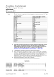
1
Cayman Islands Government MOSQUITO RESEARCH & CONTROL UNIT -AIRCRAFT SECTIONOPERATIONS MANUAL – PART B (Aircraft Operating Matters – Type Related) OPERATIONS MANUAL PART-B 0. Administration and Control of the Manual 0.1 Revision Record Revision # Date issued Revision # 0riginal 15th March 2012 4 1 5 2 6 3 7 Original 0-1 SECTION - 0 Date issued Issue Date: 15/03/12 OPERATIONS MANUAL 0.2 PART-B SECTION - 0 List of Effective Pages Part B B B B B B B B B B B B B B B B B B B B B B B B B B B B B B B B B B B B B B B B B B B B B B B B B Original Section Title Cover Page Administration and Control of the Manual Aircraft Fleet Limitations Normal Procedures Emergency Procedures Performance Flight Planning Mass and Balance Loading Use of Check Lists Minimum Equipment List Survival and Emergency Equipment Emergency Landing/Ditching Procedures Aircraft Systems 0-2 Section Page # Date 0 0 0 0 0 0 0 0 0 0 0 1 2 3 4 5 6 6 6 7 7 7 8 8 9 9 9 10 11 11 12 12 13 13 13 13 13 13 13 13 13 13 13 13 13 13 13 13 0-1 0-2 0-3 0-4 0-5 0-6 0-7 0-8 0-9 0-10 0-11 1-1 2-1 3-1 4-1 5-1 6-1 6-2 6-3 7-1 7-2 7-3 8-1 8.2 9-1 9-2 9-3 10-1 11-1 11-2 12-1 12-2 13-1 13-2 13-3 13-4 13-5 13-6 13-7 13-8 13-9 13-10 13-11 13-12 13-13 13-14 13-15 13-16 15/03/12 15/03/12 15/03/12 15/03/12 15/03/12 15/03/12 15/03/12 15/03/12 15/03/12 15/03/12 15/03/12 15/03/12 15/03/12 15/03/12 15/03/12 15/03/12 15/03/12 15/03/12 15/03/12 15/03/12 15/03/12 15/03/12 15/03/12 15/03/12 15/03/12 15/03/12 15/03/12 15/03/12 15/03/12 15/03/12 15/03/12 15/03/12 15/03/12 15/03/12 15/03/12 15/03/12 15/03/12 15/03/12 15/03/12 15/03/12 15/03/12 15/03/12 15/03/12 15/03/12 15/03/12 15/03/12 15/03/12 15/03/12 Issue Date: 15/02/12 OPERATIONS MANUAL PART-B SECTION - 0 Intentionally Left Blank Original 0-3 Issue Date: 15/02/12 OPERATIONS MANUAL 0.3 0. 1. 2. 3. 4. 5. 6. 7. 8. 9. 10. 11. 12. 13. PART-B SECTION - 0 Table of Contents Administration and Control of the Manual Aircraft Fleet Limitations Normal Procedures Emergency Procedures Performance Aerial Application Mission Planning Mass and Balance Loading Use of Check Lists Minimum Equipment List [MEL] Survival and Emergency Equipment Emergency Landing/Ditching Procedures Aircraft Systems Original 0-4 Issue Date: 15/02/12 OPERATIONS MANUAL PART-B SECTION - 0 0.4 Amendment and Revision Procedure The OMB amendment and revision procedures shall be in accordance with the procedures detailed in OMA 0.2.6. Original 0-5 Issue Date: 15/02/12 OPERATIONS MANUAL PART-B SECTION - 0 0.5 Distribution Distribution of the OMB shall be in accordance with OMA 0.2.6.5. Original 0-6 Issue Date: 15/02/12 OPERATIONS MANUAL PART-B 0.6 Abbreviations Definitions and Terminology 0.6.1 Abbreviations A A/C AFM AGB AGL Aircraft Airplane Flight Manual Accessory Gearbox Above Ground Level B BETA Zero Pitch Blade Angle (in practice between -2 to + 2 degrees) C CAACI CCW CSU CW Civil Aviation Authority of the Cayman Islands Clock Wise (when viewed from pilot’s seat) Constant Speed Unit Clock Wise (when viewed from pilot’s seat) D DFMS Digital Fuel Management System E ECTM EFP EPIRB ELT ERP ESHP Engine Condition Trend Monitoring Emergency First Response Emergency Position Indicating Radio Beacon Emergency Locator Transmitter Emergency Response Plan Equivalent Shaft Horse Power F FCL FCU FOD Fuel Condition Lever Fuel Control Unit Foreign Object Damage G GPS GPU Global Positioning System Ground Power Unit I IAS ISA ITT Indicated Air Speed (MPH) International Standard Atmosphere Inter-stage Turbine Temperature (°C) M MEL MOL MOS MRCU Minimum Equipment List Manual Override Lever Manual Override System Mosquito Research and Control Unit N Nf Ng Np Manual Override System Gas generator RPM in %. Propeller RPM Original 0-7 SECTION - 0 Issue Date: 15/02/12 OPERATIONS MANUAL O OAT OMA OMB OMC OMD OSG P P P2.5 P3 PART-B SECTION - 0 Outside Air Temperature Operations Manual – Part A Operations Manual – Part B Operations Manual – Part C Operations Manual – Part D Propeller Over-speed Governor Pa PBA PC PFD PG PLA PL PLB PIC PSI PSIG PSID Px Py PWC Pressure Gas Generator discharge pressure at station 2.5 (inter-stage [axial] compressor) Gas generator discharge pressure at station 3 (compressor [centrifugal] discharge) Used for referencing and customer bleed air. Ambient air pressure Primary Blade Angle Personal Computer Personal Floatation Device Propeller Governor Power Lever Angle (quadrant position) Power Lever Personal Locator Beacon Pilot-in-Command Pounds per Square Inch Pounds per Square Inch Gauge Pounds per Square Inch Differential FCU metering air pressure. P3 modified by a restrictor. Px modified by a restrictor. Pratt & Whitney (Canada) R RGB RH RPM Reduction Gear Box Right Hand Revolutions per Minute S SEP SHP SMS SOAP Safety Equipment and Procedures Shaft Horse Power Safety Management System Spectrometric Oil Analysis Program T T Tq Temperature °C Torque (PSIG) V VDC VFR Volts (Direct Current) Visual Flight Rules Original 0-8 Issue Date: 15/02/12 OPERATIONS MANUAL 0.6.2 PART-B SECTION - 0 Definitions: “Hot start” A start in which the maximum ITT start limit (red line) is reached or exceeded. Depending on the severity of the “hot start” the engine may be damaged or destroyed. A “hot start” will always lead to reduced engine life. “Rejected start” This is when the engine start sequence is terminated by the pilot moving the FCL to the CUT-OFF position to shut off the fuel, and then shutting off ignition and starter. “Cycle” A flight proceeded by an engine start and followed by an engine shutdown. “Abbreviated cycle” A flight from wheels up to wheels down, but without an engine start or engine shutdown. Original 0-9 Issue Date: 15/02/12 OPERATIONS MANUAL 0.6.3 PART-B SECTION - 0 Terminology THRUSH AIRCRAFT, PWC manuals and other publications use different terminology to describe the 4-lever engine power management system as fitted to PT6-60AG engines. For example: The FUEL CONDITION LEVER is referred to variously as Fuel Condition Lever, Condition Lever, Start Lever or Fuel Lever. To avoid confusion the following terminology has been adopted by MRCU and is used in all MRCU produced documents and checklists. This is consistent with terminology used by PWC: ENGINE CONTROL POWER LEVER FUEL CONDITION LEVER PROPELLER LEVER MANUAL OVERIDE LEVER Original FUNCTION AND ASSOCIATED TERMS Controls Ng and also propeller pitch at certain PLA’s. The following terminology describes various PLA’s: FLIGHT IDLE – the idle or minimum power position. The propeller is at PBA (16½° at 42 inch station). Forward of the FLIGHT IDLE position the PL controls Ng only. BETA – in this range the PL increases Ng and also moves the beta valve to change propeller blade angle towards the reverse position. REVERSE – in this range the PL controls reverse propeller blade angle (up to -11° at 42” station) but power is limited by bleeding air from the FCU pneumatic section. Controls the minimum Wf to the combustion chamber and fuel shut off to it. The FCL has 3 quadrant positions as follows: SHUT OFF – in this position Wf to the combustion chamber is stopped and the engine will shut down/ not start. LOW IDLE - in this position the minimum Wf required for start flow control and ground operations is provided. (LOW IDLE = 58% Ng with the PL at FLIGHT IDLE position) HIGH IDLE – in this position the Wf for the minimum Ng required for flight operations is provided. (HIGH IDLE = 69% Ng with the PL at FLIGHT IDLE position) The PROPELLER LEVER is connected to the CSU. It controls Np in governing mode and allows the pilot to feather the propeller. The PROPELLER LEVER has 3 quadrant positions and 1 operating range as follows: MAX RPM - in this position maximum Np (1700 RPM) will be reached when Ng exceeds approximately 75%. Selected for takeoff, climb, descent and landing. MIN RPM – in this position Np is restricted to less than 1170 RPM. Selected for all ground operations, taxi etc. OPERATING RANGE – used for cruise where Ng is sufficient to maintain the pilot selected Np between 1500 and 1700 RPM. FEATHER – propeller will feather when selected. Selected for engine start and shut down. Also for hopper loading providing the aircraft is headed into wind. The MOL is for EMERGENCY USE ONLY and provides manual control of the fuel metering valve, in the event FCU pneumatic pressure (Py) is lost. 0-10 Issue Date: 15/02/12 OPERATIONS MANUAL PART-B SECTION - 0 0.7 Introduction The OMB provides information and instructions to pilots concerning the manner in which MRCU S2RHG-T65 aircraft shall be operated. Whilst every effort has been made to ensure that the information provided in the OMB is consistent with the aircraft and engine manufacturer’s recommendations, in the event any discrepancies exist, the AFM instructions shall take precedence and are the final authority for the operation of the aircraft. Such discrepancies should be reported to management without delay. The information and procedures described in the OMD are specific to the operation of MRCU’s S2RHG-T65 aircraft. Original 0-11 Issue Date: 15/02/12 OPERATIONS MANUAL 1. PART-B SECTION - 1 Aircraft Fleet MRCU owns and operates two custom built S2RHG-T65 [Turbo Thrush] agricultural aircraft on behalf of the Cayman Islands Government which are manufactured by Thrush Aircraft Inc. 300 Old Pretoria Rd, Albany GA, 31706-3149, USA. MRCU’s aircraft are entered into the Cayman Islands aircraft register. The allocated registration numbers of the MRCU’s aircraft are Thrush Aircraft serial number T65HG-017DC – VP-CKE Thrush Aircraft serial number T65HG-013DC – VP-CKF Original 1-1 Issue Date: 15/03/12 OPERATIONS MANUAL 2. PART-B SECTION - 2 Limitations Refer to AFM Section 1. Original 2-1 Issue Date: 15/03/12 OPERATIONS MANUAL 3. PART-B SECTION - 3 Normal Procedures Refer to AFM Section 2. Original 3-1 Issue Date: 15/03/12 OPERATIONS MANUAL 4. PART-B SECTION - 4 Emergency Procedures Refer to AFM Section 3 Original 4-1 Issue Date: 15/03/12 OPERATIONS MANUAL 5. PART-B SECTION - 5 Performance Refer to AFM Section 4. Original 5-1 Issue Date: 15/03/12 OPERATIONS MANUAL 6. PART-B SECTION - 6 Aerial Application Mission Planning 6.1 Obstacle Avoidance Before conducting any low flying operation the PIC shall take all necessary measures to avoid obstacles including: Before flight, familiarizing himself with all known obstacles within all areas of intended operation. Ensuring the current obstacle database is uploaded into the WINGMAN moving map system. Conducting an inflight reconnaissance of all areas of intended operation. Ensuring that during flight measures for avoiding DGPS “light bar fixation” are observed. Original 6-1 Issue Date: 15/03/12 OPERATIONS MANUAL 6.2 Hopper Load Calculation 6.2.1 Treatment Areas/Blocks PART-B SECTION - 6 All treatment areas/ blocks currently in use are uploaded and stored in the flight track guidance system’s [SKYTRACKER] database. For flight planning purposes, to view a treatment BLOCK open SKYTRACKER on the Pilots Office PC, click on BLOCKS and open the file. Each block has a number as well as a name associated with a district or nearby geographical feature. Click on the appropriate BLOCK. The BLOCK polygon will overlay on the appropriate map of Grand Cayman, Cayman Brac or Little Cayman. To view the BLOCK acreage, right click on the mouse. Zoom in or out as necessary. Ground obstacles are marked on the appropriate island map. 6.2.2 Liquid Load Calculation To calculate a liquid load: Verify the treatment BLOCK. Verify the required swath in feet and application (ground) speed in MPH. Determine the BLOCK acreage from SKYTRACKER. Determine the product LABEL application rate of active ingredient or undiluted formulation per acre. Calculate the required application rate per acre of liquid mix, taking into account the required dilution rate, if any; Use 1 USG = 128 fluid ounces. Calculate the total amount of mix required to treat the BLOCK, taking into account the acreage. Make no allowances for cleanup runs. Calculate the aircraft work rate using the following formula: Speed in MPH X Swath in feet/493 = acres/minute. Calculate the required flow rate of mix in USGPM. Calculate the load emission/stop watch time. Calculate the load weight taking into account the specific gravity of the formulation and dilution ratio. Use a specific weight of 8.32lb per USG for water. 6.2.3 Granular Loads To calculate a granular load: Verify the treatment BLOCK. Verify the required swath in feet and application (ground) speed in MPH. Determine the BLOCK acreage from SKYTRACKER. Determine the LABEL application rate of granules in lbs/acre. Calculate the total tonnage of granules required to treat the BLOCK. Calculate the number of hopper loads required to treat the BLOCK, taking into account the required fuel weight. Calculate the aircraft work rate. Calculate the required flow rate in lbs/min. Calculate the load emission/stop watch time(s). Calculate the load weight(s) Original 6-2 Issue Date: 15/02/12 OPERATIONS MANUAL 6.3 Ferry Flights 6.3.1 Inter-Island Positioning Flights PART-B SECTION - 6 Before undertaking any positioning flight to the sister islands the PIC should check that fuel is available on Cayman Brac. For flight planning purposes use fuel consumption of 70 USGPH (from fuel records). 6.3.2 Long Range Ferry Flights Use of hopper fuel is limited to cruise flight conditions above 3000 AGL except during emergency. The auxiliary boost pump and manual ignition should be turned on prior to switching between hopper fuel and wing tanks. See also OMA 8.5.2 (d) pertaining to the requirement to use an operational flight plan. Original 6-3 Issue Date: 15/02/12 OPERATIONS MANUAL 7. Mass and Balance 7.1 General 7.1.1 Weight and Balance Computation PART-B SECTION - 7 Before each flight or series of flights the PIC shall complete a weight and balance calculation taking the following into account: (a) All items carried on-board the aircraft which are not included in the Equipment List shall be included in the weight and balance calculations. (b) Take-off and landing weights shall not exceed the maximum weights specified in the AFM. (c) Take-off and landing weights shall not exceed that which would allow the aircraft to meet performance requirements for take-off and/or landing at any airport being used. (d) Actual pilot, passenger and baggage weights shall be used. (e) The mix ratios and product densities of any formulation(s), additive(s) and carrier(s) contained in the pesticide mix, shall be taken into consideration when calculating the weight of liquid hopper loads. 7.1.2 Aircraft Weighing Following each aircraft weighing the revised Weight Schedule and Equipment List shall be incorporated into the AFM, as a revision. Using the current information the basic weight of the aircraft and basic weight center of gravity location may be calculated. Original 7-1 Issue Date: 15/03/12 OPERATIONS MANUAL PART-B 7.2 Aircraft Mass and Balance Information 7.2.1 Maximum permitted takeoff and landing weights VP-CKE VP-CKF 10,500lb max takeoff weight 10,500lb max takeoff weight VP-CKE VP-CKF 7,600lb max landing weight 7,600lb max landing weight 7.2.2 SECTION - 7 Authorized Center of Gravity Range VP-CKE Forward limit at 7600lb and below is 22.5 inches aft of datum Forward limit at 10,500lb and below is 26 inches aft of datum with straight line variation to 7600lb at 22.5 inches. Aft limit at all weights is 28.0 inches VP-CKF Forward limit at 7600lb and below is 22.5 inches aft of datum Forward limit at 10,500lb and below is 26 inches aft of datum with straight line variation to 7600lb at 22.5 inches. Aft limit 7.2.3 Aircraft Basic Weight (clean) and associated center of gravity VP-CKE VP-CKF 7.2.4 5960lbs 6035lbs 23.3 inches 24.2 inches 5939lbs 5994lbs 22.6 inches 23.0 inches Maximum Hopper Weight VP-CKE VP-CKF 7.2.7 22.36 inches 22.14 inches Aircraft Basic Weights and associated center of gravity with granular dispersal equipment fitted VP-CKE VP-CKF 7.2.6 5882lbs 5938lbs Aircraft Basic Weights and associated center of gravity with liquid dispersal equipment fitted VP-CKE VP-CKF 7.2.5 at all weights is 28.0 inches 4000lb 4000lb Maximum Hopper Volume VP-CKE VP-CKF Original 550 USG 550 USG 7-2 Issue Date: 15/02/12 OPERATIONS MANUAL PART-B SECTION - 7 7.3 Volumetric Weights of Fuel and Oil For computation purposes the following fuel and oil weights may be used: Kerosene type fuels - 6.7 lb. per gallon @ 80°F MIL-L-23699 Jet Oil - 7.5 lb. per gallon @ 80°F Original 7-3 Issue Date: 15/02/12 OPERATIONS MANUAL 8. PART-B Section - 8 Loading 8.1 Aircraft Loading The following aircraft loading procedures shall be followed: (a) All loadings shall be distributed using the current aircraft weight schedule. (b) Before flight any baggage and loose equipment shall be properly secured to the appropriate attachment (tie down) points with strapping, rope, or netting. (c) No item shall block or restrict the use of any normal or emergency exit or required piece of emergency equipment. Original 8-1 Issue Date: 15/02/12 OPERATIONS MANUAL PART-B Section - 8 8.2 Hopper Loading Procedures The PIC shall supervise hopper loading to ensure that the correct weight of material is delivered into the aircraft hopper: After hopper loading the PIC shall ensure that all loading equipment is clear of the aircraft, all delivery hoses are disconnected, side loader valves are closed and the hopper lid is securely latched. During hopper loading with the engine running a “loading supervisor” shall be designated and who shall ensure that loading personnel remain at all times behind the aircraft wing leading edge. During hopper loading operations with the engine running do not feather the propeller if the aircraft is facing out of wind. Original 8-2 Issue Date: 15/02/12 OPERATIONS MANUAL 9. PART-B Section - 9 Use of Check Lists 9.1 Aircraft Checklists It is a requirement that a printed copy of the aircraft manufacturer’s cockpit checklist covering each phase of flight must be readily available to the pilot. Photocopied or ‘amended’ personal checklists cannot be used – only those provided by MRCU may be used. Original 9-1 Issue Date: 15/02/12 OPERATIONS MANUAL PART-B Section - 9 9.2 Wingman Checklists There is no requirement to carry on-board a printed copy of the WINGMAN flight track guidance system manufacturers checklists since all check lists can be selected by navigating the on-board touch-screen menu. On “boot-up” the touch screen menu defaults to the pre-flight check list. Original 9-2 Issue Date: 15/02/12 OPERATIONS MANUAL PART-B Section - 9 9.3 Checklist Discipline The read-and-do checklist contains the minimum items to operate the aircraft safely. When using checklist’s pilots should use good checklist discipline and: Avoid rushing. If the checklist is interrupted, start it again. Avoid using the checklist during periods of high work load. The time critical emergency checklist contains “memory items” which should be checked against the check list if and when time and flight conditions allow. Finally remember to fly the aircraft ahead of any other items. Original 9-3 Issue Date: 15/02/12 OPERATIONS MANUAL 10. PART-B Section - 10 Minimum Equipment List [MEL] MRCU has elected not to produce an MEL for its S2RHG-T65 aircraft. Since any defect recorded in the Technical Log invalidates the C of A, except in accordance with OMA 8.6.3 no flight shall commence with any known defect, inoperative or malfunctioning aircraft system. Original 10-1 Issue Date: 15/02/12 OPERATIONS MANUAL 11. PART-B Section - 11 Survival and Emergency Equipment All survival and emergency equipment shall be used according to the manufacturer’s instructions. 11.1 Retrievable Emergency/Survival Equipment 11.1.1 On-board Equipment For all flights, the following removable emergency/survival equipment shall be carried on-board the aircraft: First aid equipment of good quality and sufficient in quantity for two persons. PFD (Personal Flotation Device) for each occupant, equipped with a whistle and waterproof torch. Type 406 EPIRB. Hand held electric torch/flashlight. Survival box containing parachute rocket distress signal kit and whistle. Fire Extinguisher. Spare-Air canister(s) for emergency underwater egress (gives approximately 57 surface breaths). 2-man inflatable life raft, attached to the aircraft with a retaining line. 11.1.2 Personal Equipment Personal issue Type 406 PLB’S should be carried on all flights. Original 11-1 Issue Date: 15/02/12 OPERATIONS MANUAL 11.2 PART-B Section - 11 Non-Retrievable Emergency Equipment: 11.2.1 Emergency Locator Transmitter The non-retrievable (fixed to airframe) ELT is equipped with a cockpit control switch which is situated on the upper right instrument panel within the pilots reach. With AUTOMATIC mode selected, the ELT is activated by an impact “G” switch. By positioning the ELT cockpit switch to the “ON” position the ELT is manually activated. If an emergency situation requires activation it is preferable to manually activate the ELT. 11.2.2 Spider S3 on-line aircraft tracking system MRCU subscribes to the Spider S3 on-line aircraft tracking system. The system uses satellite, web and mobile technology to alert MRCU that a state of emergency exists or may exist. To view the Spider S3 User Manual click link. Original 11-2 Issue Date: 15/02/12 OPERATIONS MANUAL 12. PART-B Section - 12 Emergency Landing/Ditching Procedures In the event that an off-airport landing or ditching is imminent, the PIC shall give priority to avoiding built-up areas and controlling the aircraft to the surface. The following procedures should be adopted in emergencies, according to circumstances. 12.1 Before an Emergency Landing or Ditching If time permits, the PIC should: On aerial application flights, jettison (dump) hopper contents. Determine the wind direction and strength and set up an approach pattern. Follow the emergency procedures specified in the Emergency Check List. Transmit precise details of location to ATC. Manually activate the ELT. Manually trigger a Spidertracks S3 alert. Ensure that all seat belts/shoulder harnesses are fastened securely, and that all loose articles are secured. Prepare the passenger, if carried, for the impending emergency. When landing in water: avoid landing into the face of primary swells unless wind speed is extremely high. The best ditching heading is usually parallel to the primary swell. In strong winds it may be desirable to compromise by ditching more into the wind and slightly across the swell system. Original 12-1 Issue Date: 15/02/12 OPERATIONS MANUAL PART-B Section - 12 12.2 After an Emergency Landing or Ditching After an emergency landing the PIC should, if able: Order and assist the passenger, if carried, to evacuate the aircraft, preferably upwind. Ensure the passenger moves a safe distance from the aircraft. Retrieve accessible emergency and survival equipment and abandon the aircraft. Activate the hand-held PLB. After an Emergency Ditching After an emergency ditching the PIC should, if able: Order and assist the passenger, if carried, to evacuate the aircraft. Retrieve accessible emergency and survival equipment. Deploy and inflate the life raft and assist the passenger into it. Load emergency equipment into the life raft. Cut the life raft retaining line. Activate the hand held PLB. Original 12-2 Issue Date: 15/02/12 OPERATIONS MANUAL 13. PART-B Section - 13 Aircraft Systems 13.1 Engine The information provided in OMB Section 13 is supplementary to that provided in the AFM. 13.1.1 Leading Engine Particulars Manufacturer Model Dry weight Engine diameter Engine length Oil Tank Capacity Oil Tank Expansion Space Oil Tank Usable Quantity Gas generator rotation Power section rotation Propeller shaft gear ratio United Aircraft of Canada PT6-60AG 478 lb. with standard equipment 19.0 in. approx. at room temperature 72½ in. approx. at room temperature 2.5 USG 0.7 USG 1.5 USG CCW at ± 37,468 RPM (100% Ng) CW at ± 29992 RPM (100% Ng) 0.0568:1 13.1.2 Engine Reference Stations To refer to pressure (P) or temperature (T) at a specific point in the gas path within the engine the following (PWC) numbers are used: Station # 1 2 2.5 3 4 5 6 7 Location Air Intake Gas generator intake (at the first stage blades) Gas generator inter-stage Gas generator discharge pressure Gas generator turbine inlet Inter-turbine (Hence ITT sometimes referred to as T5) Turbine exhaust duct (ski-jump area) Exhaust outlet (exhaust stack mounting flange area) 13.1.3 Engine Power Formulas For PT6A-60 series engines to convert PSID to ft.lb Ft.lb. = PSID X 83.63 For PT6A-60 series engines to calculate ESHP: ESHP = Tq (ft.lb) X Np / 5252 For PT6A-60 series engines to calculate SHP: SHP = Torque (ft-lb) X Np divided by 5253 For example: Max Tq is 38.8 PSIG at 1700 RPM = 3245 ft-lb SHP = 3245 X 1700/5253 SHP = 1050 Original 13-3 Issue Date: 15/02/12 OPERATIONS MANUAL PART-B Section - 13 13.1.4 Engine Power Limits (Sea Level Static Output, Standard Day) OPERATING CONDITION ESHP4 SHP TAKEOFF MAX. CONTINUOUS MAX. CRUISE NORMAL CRUISE 1113 1081 1050 1 1020 1 955 900 2 Specific Fuel Consumption (lb./eshp/hr.) 0.548 Jet Thrust (lb.)3 158 158 158 Available to 34.4°C @ 1700 RPM Np Available to 32.8°C @ 1700 rpm Np 3 Jet Thrust is supplemental thrust generated by engine exhaust. 4 ESHP = SHP + Jet (exhaust) thrust 1 2 NOTE A: PT6A series engine power ratings are determined by the rotational torque the engine is capable of applying to the propeller shaft under ISA conditions. Maximum engine output is established for each engine model according to its design; however, engine output is flat rated to a SHP suitable for its application. Flat ratings are an airframe limitation. For example the Tq red line may be reduced to restrict torque. The PL may then be advanced in a climb to altitude to maintain maximum torque, provided ITT is kept within operating limits. De-rated engines are those where the power producing capability of the engine is intentionally inhibited. With de-rated engines during a climb torque will diminish with altitude from airport elevation. NOTE: B The PT6A-60AG engine is flat rated & not fitted with over-torque limiter. Pilots must therefore remain vigilant to prevent an over-torque or over-temperature condition occurring. PT6A-60AG engines as fitted MRCU aircraft are flat rated at 1050 SHP for takeoff and 1020 SHP for continuous operation. NOTE: C The AG suffix on agricultural PT6A-60 AG engines denotes that the engine may be run indefinitely on AFM approved grades of diesel fuel without compromising engine manufacturer’s warranties. Note that the THRUSH AFM does not permit the use of diesel fuel. Original 13-4 Issue Date: 15/02/12 OPERATIONS MANUAL PART-B Section - 13 13.1.5 Engine Operating Limits Operating Conditions2 SHP Torque1 Maximum Observed ITT °C Ng Np TAKE OFF MAX. CONT. 1050 1050 ft.lb 3625 3625 PSIG 38.8 37.7 820 775 9 RPM 39000 8 39000 % 104 8 104 RPM 1700 1700 MIN. IDLE START TRANSIENT MAX REVERSE 900 - - 750(max) 1000 4 850 5 760 21750 39000 - 58 6 104 - 1870 1650 Oil Press. PSIG3 Oil Temp. °C7 % 100 100 90 - 135 90 - 135 55-110 8 55 -99 110 94.4 60 (min) 200(max) 40-200 5 100-135 -40 -110 8 -40 (min) 0-110 0-104 NOTE: Maximum Tq & ITT are a limit, not a target. Whenever possible use lower figures to extend engine life. 1 Tq limit applies within range of 1000 to 1700 RPM Np. Below 1000 RPM Tq is limited to 2000 ft.lb/23.9 psig 2 Limit for engine operation is SL to 12,000 ft. Oil pressures below 90 PSIG are undesirable. Under emergency conditions to complete a flight, a lower oil pressure limit of 60 PSIG is permissible at a reduced power level not exceeding 2000 ft.lb / 23.9 PSIG Tq. 3 Oil pressures below 60 PSIG (Ng above 72%) are unsafe and require a landing be made as soon as possible using the minimum power required to sustain flight. If oil pressure falls below 40 PSIG the propeller will feather. 4 Limited to 5 seconds 5 Limited to 20 seconds 6 Applies to range 21000 to 23000 rpm Ng. Advance Power Lever to maintain this value Oil temperature limits are -40° to 99°C with limited periods of 10 minutes at 110°C. For increased engine service life maintain oil temperature below 80°C. Normal oil temperature with Ng above 69% is 60° to 70°C. For proper Fuel Heater operation, minimum oil temperature at takeoff is 55°C. 7 8 Limited 9 Max to 10 minutes. continuous power is ITT limited to 775°C provided Tq does not exceed 37.7 psig @ 1700 rpm Original 13-5 Issue Date: 15/02/12 OPERATIONS MANUAL PART-B Section - 13 13.1.6 General Description The PT6A series engines are reverse-flow combustion, free turbine engines. The term “reverse-flow” refers to the engine design feature in which the air enters the intake at the rear of the engine, flows forward toward the nose case, and exits through a forward exhaust stack. The term “free-turbine” refers to the design feature in which the power section has no physical connection with the gas generator section. Instead the air passing through the engine acts as a fluid coupling between the two turbine sections. This allows the two rotating engine assemblies to (1) operate independently of one another; (2) operate at differing speeds & (3) turn in opposite directions to counter gyroscopic forces. The practical advantages of the free-turbine design area) It allows the pilot to control Ng and Np independently of each other. b) Starter cranking Tq is low since only the compressor is initially rotated during the start sequence. The gas generator section includes the compressor and the combustion sections. It draws air into the engine, adds energy to it in the form of fuel, and produces the hot expanding gases necessary to drive both the compressor and power turbines. The power section consists of the power turbine(s) and two-stage planetary reduction gearbox which drives the propeller. Power to the reduction gearbox is derived solely from the exhaust gas flow across the power turbine after it has passed through the gas generator. The power turbine converts the exhaust gas flow into rotational motion. The reduction gearbox converts the high speed, low Tq of the power turbine to the low speed, high Tq required to drive the propeller. An integral oil tank is located between the inlet case and the accessory gearbox. It provides oil to bearings, propeller, torque system etc. 65% of the energy produced by the engine is used to drive the compressor turbine: 35% used to drive the power turbine. All accessories, including the FCU, are driven off the gas generator section through an accessory gearbox at the rear of the engine. The hydro-mechanical FCU regulates fuel flow to fuel nozzles in response to power requirements and flight conditions. 13.1.7 PT6-60AG Engine Features (as fitted to MRCU aircraft) The AG (Agricultural) engine designation means the engine can be operated indefinitely on AFM approved grades of diesel fuel without compromising the engine manufacturer’s warranty. However engines fitted to agricultural aircraft are excluded from the PWC Eagle Maintenance Program. Features: Fitted with four lever power management system - PL, FCL, Propeller Lever and MOL. Fitted with hydro-pneumatic (Woodward) FCU. Fitted with 5 blade Hartzell variable speed propeller with reverse thrust. Fitted with K&N inlet air filtration system. Fitted with engine driven Low Pressure Fuel Pump. Not fitted with reserve power capability. Not fitted with a torque limiting device. Not fitted with electronic ECTM recording device (“Squealer Box”). Not fitted with auto-ignition. Original 13-6 Issue Date: 15/02/12 OPERATIONS MANUAL PART-B Section - 13 13.1.8 Engine Air Filtration System 13.1.8.1 Description Aircraft are fitted with a K&N air filtration system. The system consists of a rechargeable air filter which filters the air entering the plenum. The filter is located at the bottom of the engine cowling, directly underneath the engine and provides protection against FOD. The air filter condition indicator, located on the lower left instrument panel should be checked before each take off. If the air filter condition indicator needle enters the red arc discontinue the flight. Have the filter element cleaned or replaced before further flight. 13.1.9 Engine Ice Protection 13.1.9.1 Description The K&N air filtration system does not provide protection against inlet icing. Engines are not fitted with an inertial separator (ice vane) to protect the engine from FOD (ice, snow etc.) Therefore flight into known icing conditions is prohibited. Flight in visible moisture below 40°F is prohibited. This would preclude flight in cloud above an altitude of ± 5500 feet on a standard day. Engines are fitted with an oil-to-fuel heater see notes on fuel system. 13.1.10 Gas Generator 13.1.10.1 Description The gas generator section, which includes the compressor and compressor turbine turns CCW at ± 37,468 RPM. It consists of 4 axial rotors, 1 centrifugal impeller and 1 compressor turbine. The 1st stage axial rotor blades are constructed of titanium to help protect against FOD. The 2nd to 4th stage axial rotor blades constructed of stainless steel. The axial rotors are more efficient than the impeller at low Ng. Each axial stage accelerates the air which is then decelerated through divergent stator vanes, thus increasing air pressure. The dynamic pressure (air velocity) generated by the centrifugal impeller is converted into static pressure by the divergent shaped diffuser pipes which reduce air velocity and increase compressor discharge pressure (P3). The compressor inlet wire mesh screen is designed so that no PWC engine parts can penetrate through it. This does not include locking wire etc. 13.1.10.2 Troubleshooting Any increase in Ng, ITT and Wf is usually indicative of a gas generator problem. Indications of compressor rotor assembly imbalance are vibration or a “humming” noise. 13.1.11 Compressor Bleed Valve 13.1.11.1 Description The compressor is fitted with a bleed valve which prevents compressor stall at low Ng. Two forces act on the bleed valve piston. Px air pressure acts to close the valve and P2.5 acts to open it. At low Ng Px is lower than P2.5. As Ng increases Px rises faster than P2.5 and gradually closes the valve. Normally it is fully closed at ± 91% Ng under ISA conditions. The convergent/divergent orifices which provide metering to the compressor bleed valve are FACTORY SET AND NOT FIELD ADJUSTABLE. The practical importance of the compressor bleed valve being fully closed at ± 91% Ng (under ISA conditions) is that this represents the most fuel efficient operating Ng because no P2.5 is being “dumped”. The maintenance program requires a “daily” compressor desalination wash. Compressor surge is usually caused by poor engine handling or a faulty compressor bleed valve. Original 13-7 Issue Date: 15/02/12 OPERATIONS MANUAL PART-B Section - 13 13.1.12 Hot Section 13.1.12.1 Description The “hot section” consists of those engine components downstream of the compressor - the combustion chamber, compressor turbine, power turbines etc. 13.1.13 Temperature Indicating System 13.1.13.1 Description The system provides the pilot with an indication of engine temperature between the compressor turbine and 1st stage power turbine (Station 5). The system consists of as 10 thermocouples for measuring T5 (ITT), 1 positive bus bar, 1 negative bus bar, 1 trim probe and 1 wiring harness. As T increases, an increased voltage is generated by each thermocouple. Because of uneven heat distribution within the gas path individual thermocouples will generate different voltages. An average reading is obtained by wiring the thermocouples in parallel. The trim probe located over the inlet case corrects sampling errors and biases the average T. The resultant ITT is read in the cockpit. 13.1.13.2 Pilot Notes Max ITT (5 seconds for start and 20 seconds during takeoff) is 820°C- red radial. Max. Continuous ITT is 775°C – top of green arc. At engine shut-down feather the propeller, allow ITT to stabilize for at least 2 minutes below 650° before placing the FCL in the fuel SHUT-OFF position. This will minimize thermal shock, oil cocking in the bearings, and fuel nozzle tip cocking. 13.1.14 Power Section 13.1.14.1 Description The Power Section consists of dual stage (2) power turbines which turn CW at ± 29094 RPM. The heavy duty power turbine housing is designed to act as a containment ring, should power turbine blade failure occur. There have been no reported in-flight engine fires on PT6A series engines. 13.1.14.2 Pilot Notes During pre-flight inspection slowly turn the propeller in normal direction of rotation and listen for unusual noises and feel for tightness. Original 13-8 Issue Date: 15/02/12 OPERATIONS MANUAL PART-B Section - 13 13.1.15 Reduction Gearbox 13.1.15.1 Description The RGB consists of a two stage planetary 17.1:1 reduction gearbox which includes a hydraulic torque (Np) measuring system. The following Tq limits are applicable to PT6A-60AG engines. Tq/RPM limitations may be read from the placard on the instrument panel adjacent to the torque meter. Max. Tq for takeoff is 38.8 PSIG at 1700 RPM – red line. Max. Continuous Tq is 37.7 PSIG at 1700 RPM – top of green arc. For Max. Continuous Tq settings at less 1700 RPM refer to instrument panel placard. Max. Tq below 1000 RPM is 23.9 PSIG – see instrument panel placard. 13.1.15.2 Pilot Notes The main causes of RGB failure are over-torque and oil contamination. Since engines are not fitted with a Tq limiting device over-torque may result in spalling of reduction gear teeth and subsequent RGB failure. After engine shut down the propeller must be secured to prevent propeller wind milling which may result in spalling of reduction gear teeth since no lubrication is being provided. Good practice is to descend with power on to maintain Tq meter pressure so the engine drives the propeller. Move the propeller lever to HIGH RPM and avoid low Tq, high rates of descent. The rule is “time to climb is time to descend”. 13.1.16 Lubrication System/Main Bearings 13.1.16.1 Description: 7 main bearings support the 3 main rotating assemblies as follows: The gas generator shaft is supported by (rear) 1 ball bearing which withstands rearward thrust and (front) 1 roller bearing which supports radial loading. The power turbine shaft is supported by (rear) 1 roller bearing which supports radial loading and (front) 1 ball bearing which supports forward thrust. The propeller shaft is supported by 2 roller bearings which support radial loadings and 1 ball bearing which supports forward thrust. 13.1.16.2 Pilot Notes Roller bearings permit axial rotor movement which is required for thermal expansion. The oil filler cap has the (new design) safety ball check valve to restrict oil flow out of the oil tank. Grey color (new design); Yellow color (old design without check valve). Main bearings require preventative maintenance only – oil changes, inspection/change of oil filters etc. every 800 hrs. The integral oil tank is located between the inlet case and accessory gearbox. A main bearing failure will result in a catastrophic engine failure. Do not start the engine if oil is seen dripping from cowl at the six o’clock position. Ensure oil pressure is kept within AFM limits during ground and flight operations (90-135 PSI). Caution range (yellow arc) is for idling and emergency completion of a flight using 24 PSI torque (2000 ft.lb) or below. A SOAP sample is taken and sent away for analysis every 25 flight hours. Original 13-9 Issue Date: 15/02/12 OPERATIONS MANUAL PART-B Section - 13 13.1.17 Oil Checking 13.1.17.1 Pilot Notes To avoid overfilling of oil tank, and high oil consumption, an oil level check is recommended within 30 minutes after engine shutdown. Ideal interval is 15 to 20 minutes. If more than 30 minutes has passed, and the dipstick indicates that oil is needed, start the engine and run at ground-idle with propeller feathered for five minutes, then recheck oil level. Procedure Shut down the engine. Unlock the filler cap and dipstick from the filler neck at the eleven o’clock position on the accessory gearbox and remove the filler cap. Wipe dipstick with clean lint free cloth. Check oil level against marking on dipstick and service as required. Normal oil level is between MAX HOT and one US quart below MAX HOT. Install filler cap/dipstick and lock. Check the oil dip stick/filler cap is secure. When filler cap assembly is installed and locked, no movement is allowed. If oil levels are checked with engine cold, level should be 1-2 quarts too low. USE ONLY MOBIL JET II; Maximum allowable oil consumption is 0.3lb/hr. 13.1.18 Ignition System 13.1.18.1 Description The spark igniter system is manually operated from the cockpit and consists of an “exciter box”, high tension cables and two spark igniters. The “exciter box” transforms DC voltage into high-energy electrical pulses that are supplied to the spark igniters through the high tension cables. The high tension cables are encased in flexible metal braid for protection from heat. The spark igniters are situated at the four and nine o’clock position on the gas generator case and extend inward to the combustion chamber through its outer liner. To reduce risk of failure and extend service life igniters are cooled by secondary air. The system is designed so that if either igniter fails, the opposite igniter will remain operable. 13.1.18.2 Pilot Notes The rule is “FIRE BEFORE FUEL” – during the engine start sequence verify Ng is above 13%, check MOL and FCL are in the OFF position, then turn the ignition is ON (aural and ignition warning light) before moving the FCL from the shut-off to the low idle position. Never attempt an engine start using internal/aircraft batteries unless the voltmeter indicates a minimum of 20 VDC. Since the “spark frequency” is dependent on the VDC supplied to the exciter box, if voltage has fallen below 17VDC when the ignition is turned ON a “hot start” may result. If turbulence is encountered during flight or the possibility of fuel interruption exists switch the Igniters ON. Differentiate between starting on internal (aircraft) batteries and GPU as follows: When starting the engine on internal batteries as soon as 13% is reached, check a minimum of 17 VDC, switch the Ignition ON, and then place the FCL in the LOW IDLE position. This is preferable to using the available battery power to achieve a higher Ng and lower spark frequency. Reject the start if light-off does not occur within 10 seconds. When starting the engine using external power regulate the GPU to 28 VDC and 1000 amps. Stabilize Ng as high as possible above 13% before switching the ignition ON and placing the FCL in the Low Idle position. Reject the start if light-off does not occur within 10 seconds. Original 13-10 Issue Date: 15/02/12 OPERATIONS MANUAL 13.2 PART-B Section - 13 Propeller System 13.2.1 General The propeller system consists of a fully feathering variable speed propeller with reverse thrust, propeller governor [PG] and airframe installed over-speed governor [OSG] 13.2.2 Leading Propeller Particulars 13.2.2.1 Description Manufacturer: Hartzell Model: HC- B5MP-3C Hub Model DesignationHC - B 5 M P – 3 C Hartzell Controllable HC - B 5 M P – 3 C Single shoulder retention HC - B 5 M P – 3 C Number of blades (5) HC - B 5 M P – 3 C Basic shank - has two needle bearings, C 1977 Clamp HC - B 5 M P – 3 C 4.25” bolt circle, 4 dowels, ½” diameter, 8 x 9/16” bolts or studs HC - B 5 M P – 3 C Constant speed, feathering, reversing, PT6; external BETA ring HC - B 5 M P – 3 C Minor modifications to pilot tube o-ring, piston nut etc Minimum diameter 110.7 inches Maximum diameter 111.2 inches Pitch (42 inch station) 16½º, 79º feather, -11º reverse. Weight 230lbs (weight of spinner extra) 13.2.2.2 If Tq or oil pressure indications are abnormal during flight, land as soon as possible. Engine operation with oil pressure below 60 PSIG is unsafe and below 40 PSIG the propeller will feather. Stabilized ground operation between 400-900 RPM and 1170-1400 RPM is prohibited. This is a propeller manufacturer limitation (harmonics/resonance). Taxi between 900 -1170 RPM to avoid the restricted (transient only) range Accelerate through the restricted range (1170 – 1400 RPM) only after the aircraft is lined up for takeoff. Feather and unfeather the propeller on the ground during engine start and shut-down or with the aircraft headed into wind. Except in emergency do not intentionally feather the propeller during flight. Do not move the PL aft of the FLIGHT IDLE stop during flight. USE OF REVERSE THRUST IN FLIGHT MAY LEAD TO LOSS OF CONTROL. Do not move the PL aft of the FLIGHT IDLE gate towards the reverse position with the engine stopped or damage to the propeller reverse linkage will result. Except to decelerate the aircraft during the landing roll-out avoid using reverse thrust during ground operations. During taxi use BETA range only. Do not use reverse thrust to park the aircraft. Feathering the propeller before engine shut down allows oil from the propeller and RGB to make its way back to the oil tank and provide more consistent oil level checks. 13.2.2.3 Pilot Notes Troubleshooting If oil pressure indication is too low or lost but Tq indications are normal and the propeller will govern this is usually indicative of an oil pressure indicating system fault. If Tq indications are abnormal but oil pressure is normal this is usually indicative of a Tq indicating system fault. Original 13-11 Issue Date: 15/02/12 OPERATIONS MANUAL PART-B Section - 13 13.2.3 Constant Speed Unit 13.2.3.1 Description The purpose of the CSU is to control the amount of oil going in/out of the propeller to allow for propeller speed control and feathering. 13.2.3.2 Pilot Notes There are 4 modes of CSU operation: FEATHERING MODE – this is achieved by moving the Propeller Lever to the FEATHER position. Oil is dumped from the propeller into the RGB. GOVERNING MODE – the range of operation, typically 75-100% Ng, where engine power is sufficient to maintain the pilot selected propeller RPM by varying the blade angle. In the governing mode the pilot controls Ng with the PL and propeller RPM with the Propeller Lever. BETA MODE FORWARD - the range of operation where the blade angle is at PBA (16½º at 42 inch station). This is a direct function of the beta valve position. This range is used on the ground or during low power flight with the PL at the FLIGHT IDLE stop position. BETA MODE REVERSE – the range of operation where the blade angle is between the PBA and reverse (16½º and -11º at 42 inch station). This is a direct function of the beta valve position. This range is used on the ground with the PL aft of the FLIGHT IDLE stop gate position. Power is limited in this range by bleeding air from the FCU pneumatic section. 13.2.4 Over-speed Governor 13.2.4.1 Description The OSG is an airframe provided option which provides hydraulic backup protection against propeller and power turbine over-speed. It will limit Np to approximately 4% above maximum propeller speed (1700 RPM). 13.2.4.2 Pilot Notes Check the OSG daily in accordance with AFM procedures 13.2.4.3 Troubleshooting If the primary propeller governor (CSU) fails the OSG will limit propeller RPM to 104% of max Np (1700 X 1.04 = 1768 RPM). 13.2.5 Nf Governor 13.2.5.1 Description The Nf governor provides pneumatic protection against propeller and power turbine over-speed. In forward propeller operation it will limit Np to approximately 6% above selected propeller speed. In reverse propeller operation it will limit propeller speed to approximately 5% below selected propeller speed. 13.2.5.2 Troubleshooting If the CSU governor and OSG both fail the Nf governor will limit Np to 106% of max. Np. (1700 X 1.06 = 1802 RPM) by bleeding Py from the FCU. This will be accompanied by a reduction in Ng and Tq. Failure of all three governors (CSU, OSG, Nf) will result in an uncontained engine failure (runaway engine). If time permits move the FCL to the SHUT OFF position. Original 13-12 Issue Date: 15/02/12 OPERATIONS MANUAL 13.3 PART-B Section - 13 Aircraft Fuel System 13.3.1 Airframe Components: The major aircraft fuel system components and sequence of fuel passage through it are as follows: 13.3.1.1 Wing Tank(s) Fuel is stored in TWO integral (wet wing fuel tanks) each of 115 USG capacity, one in each wing, located just outboard of the fuselage. The wing tanks are serviced through filler ports located on the top of each wing. Ports are visible from the pilot’s seat and incorporate security chains to prevent loss of fuel caps. The following placard is located adjacent to each filler cap: FUEL 115 GAL. CAP, JET A, JET B, JP-4, and JP-5 The wing tanks are vented at the outboard and inboard end of each tank via vent lines to a centrally located vent system in the fuselage. Ram air enters the vent system during flight via a vent scoop located under the left wing. This pressurizes the system to maintain a positive pressure in the fuel tanks. Each wing tank has a fuel drain located in the lower wing skin. 13.3.1.2 Header Tank The two wing tanks are interconnected through a 5 USG header tank located in the lower fuselage below the cockpit. The header tank has a fuel drain located under the fuselage, beneath the cockpit area. 13.3.1.3 Fuel Tank/Hopper Selector Valve A two position selector valve is mounted on the lower left cockpit wall below the door and within the pilot’s reach. A fuel supply line is permanently routed from the header tank to the selector valve. When the long range-fuel (hopper) system is fitted a second fuel line is routed from the bottom of the hopper directly to the selector valve. When the long-range system is not in use this fuel line is disconnected and the tank selector valve wire-locked in the FORWARD (header-tank feed) position. When the long-range system is fitted, hopper fuel is selected when the valve is moved to the UP position. 13.3.1.4 Fuel Shut-Off Valve The two-position ON/OFF fuel shut-off valve is located within the pilot’s reach, on the lower left side of the cockpit. With the fuel shut-off valve positioned in the OFF position, the fuel supply is shut-off upstream of the electric Boost Pump. 13.3.1.5 Boost Pump (electric) The fuel pump is installed on the lower left side of the fuselage beneath the cockpit floor. The pump is electrically controlled by a two-position ON/OFF switch labeled AUX PUMP, located on the start and light panel to the lower left of the pilot’s seat. The pump is an electrically driven positive displacement vane type pump with siphon type relief valve and provides fuel pressure of 21 – 23 PSI. The Boost Pump provides (1) boosted pressure and lubrication to the engine driven high pressure pump during engine starting below 5% Ng and continuous back-up fuel pressure, should the engine-driven low pressure pump fail. 13.3.1.6 Fuel Filter: The fuel supply is routed from the Boost Pump through a 25 micron fuel filter located on the left hand side of the fire-wall, to the engine driven low pressure pump. The fuel filter is fitted with a drain valve and incorporates a by-pass. PILOT NOTES: Before flight check for leaks, that the by-pass indicator grommet has not “popped”, and drain and check a filter fuel sample. Do not start the engine if water or excessive sediment is detected in the firewall fuel filter because the High-Pressure Fuel Pump outlet filter must be replaced first. Original 13-13 Issue Date: 15/02/12 OPERATIONS MANUAL PART-B Section - 13 13.3.2 Engine Fuel System Components 13.3.2.1 Low-Pressure Fuel Pump The engine driven geared pump is mounted at the rear of the scavenge pump on the accessory gearbox and located upstream of the Fuel Heater and downstream of the firewall Fuel Filter. The pump provides a positive head of at least 5 PSI at the engine driven High Pressure Fuel Pump inlet above 5% Ng. 13.3.2.2 Fuel pressure Indication System Fuel pressure is mechanically routed directly from the outlet port of the Low Pressure Fuel Pump to the cockpit fuel pressure gauge. Minimum allowable fuel pressure is 5 PSIG; maximum fuel pressure is 50 PSIG. 13.3.2.3 Fuel Heater The Oil-To-Fuel Heater is located immediately upstream of the High Pressure Fuel Pump. It uses warm engine oil to maintain the desired fuel inlet temperature and thus prevent filter icing at the pump. This is carried out automatically using a vernatherm type temperature sensor and requires no pilot action from the cockpit. The AMS requires periodical checks to verify the Fuel Heater is not operating at excessive temperatures. 13.3.2.4 High-Pressure Fuel Pump The primary purpose of the pump is to deliver unmetered high pressure fuel (P1) to the FCU. Since the pump is driven by the compressor section accessory gearbox, flow rates and pressures will vary with changes to Ng. The FCU pressure relief valve prevents system over pressurization by opening when P1 exceeds 1000 PSID, thereby returning excess fuel pressure (P0) to the High Pressure Fuel Pump inlet. The pump is a single stage, positive displacement, gear-type pump with both inlet and outlet filters. The self-relieving inlet filter is a (74 micron) metallic mesh type non-repairable filter. The inlet filter self-relieves at 1.5 PSID should it become obstructed. The (10 micron) outlet filter is of the disposable non-metallic type. Should the outlet filter become obstructed a bypass valve, preset to 15 -25 PSID will open to allow fuel to be delivered to the FCU. The outlet filter must be replaced if contamination is found in the firewall Fuel Filter. THE ENGINE WILL FLAME OUT AND CANNOT OPERATE IF THE HIGH PRESSURE FUEL PUMP FAILS. This is because fuel at high pressure is required to shuttle the FCU pressurizing and dump valve. By providing lubrication to the High Pressure Fuel Pump bearings by correct use of the Boost Pump and ensuring the outlet filter is replaced if the Firewall Fuel Filter becomes contaminated pilots will help reduce the risk of High Pressure Pump failure. 13.3.2.5 High-Pressure Fuel Pump to FCU Coupling If the coupling between the High Pressure Fuel Pump and the FCU fails, Ng will go to ± 85%. Any movement of the PL will have no effect. If the coupling fails during flight, land as soon as practical. Jettison hopper contents only if necessary to maintain altitude. Exercise caution when landing as Ng is higher than normal and reverse thrust is not available. 13.3.2.6 Fuel Control Unit The FCU is a hydro-pneumatic (Woodward) FCU fitted with emergency Manual Override System. The FCU determines the correct fuel schedule for the required power depending on PLA, Ng, Pa and P3 signals. Fuel is then directed to the Flow Divider (or start flow control).When the FCL is placed in the FLIGHT IDLE position this sets the minimum flight power by moving the FCU input arm a predetermined distance to achieve the required Ng and engine power. To achieve the minimum spool-up time for go around or reverse thrust operation the FCL must be in the FLIGHT IDLE position and the PROPELLER LEVER in the HIGH position. If the FCU fails due to loss of Py reference air the engine will spool down to 30 -50% Ng dependent on altitude. Refer to MOS notes for indications of FCU pneumatic pressure (Py) failure and emergency use of MOL. Blue grease is used to lubricate the internal mechanism of the FCU. If there is an internal fuel leak in the FCU it will wash out the grease through a small hole at the base of the FCU. If blue grease residues are detected at the base of the FCU, THE AIRCRAFT MUST NOT BE FLOWN and the FCU must be replaced or overhauled. Original 13-14 Issue Date: 15/02/12 OPERATIONS MANUAL PART-B Section - 13 13.3.2.7 Manual Override System The MOS is designed to mechanically restore Wf in the event FCU reference pressure (Py) is lost. This is achieved by the pilot manually controlling the FCU bellows to simulate Px air pressure and thus control engine power. Py loss results in a partial power failure and not a “flame-out” because when Py is lost Wf drops to minimum flow. Indications that Py is lost is a sudden rapid loss of Tq to zero PSIG, followed closely by loss of Ng; ITT drops approximately 150º at the same rate as Ng; Wf drops to minimum flow; Ng will stabilize at 30 – 50% dependent on altitude (30% below 10,000 feet) after 15 – 30 seconds if no action is taken by the pilot (± 15 seconds at low altitudes). Moving the MOL below 50% Ng will result in compressor stall or create an over-speed, over-torque or over-temperature condition with a rapid rise in ITT to above 1000ºC & destruction of engine. The above implies that at low altitudes a reacceleration of the engine using the MOL following Py loss is unlikely. Therefore pilots should assume that sudden Tq loss at low altitude will necessitate an off-airport forced landing. Obviously this does not rule out attempting to relight and reaccelerate the engine providing the Tq loss is not preceded by or accompanied by indications which would make a reacceleration inadvisable; i.e. vibration, “runaway ITT”, loss of oil pressure, etc.When using the MOL use the following guidelines: Do not move the Power Lever. Some movement of the MOL resulting in no Ng increase is normal (dead-band). The MOL is very sensitive and once the lever is moved through the “dead-band” engine response is more rapid than when using the PL. The rate of engine acceleration is determined by the speed at which the pilot moves the lever. A rapid increase in MOL position towards maximum is to be avoided, as this can cause engine surge, engine overtemperature, Ng over-speed or over-torque. The “dead band” is affected by altitude. At lower altitudes the “dead band” is ± ½ of full travel. At higher altitudes (+10,000 feet) the “dead band” is ± one third of full travel. Keep Ng above 65% after engine reacceleration. During the approach slowly reduce Ng to +75% Ng with the MOL. NEVER move the PL aft of the flight idle stop when using the MOL. Doing so may cause the propeller to move to full reverse pitch or an over-speed condition may occur. Reverse thrust will not be available during the landing roll-out. After landing, if possible, clear the active runway before coming to a complete stop. DO NOT ATTEMPT to taxi the aircraft using the MOL. Once the aircraft has come to a complete stop shut the engine down. 13.3.2.8 Flow Divider The flow divider separates the starting fuel flow from the normal running fuel flow before it is delivered to the fuel manifolds and fuel nozzles. A “hung start” is usually caused by a faulty flow divider. Indications are Ng stops increasing at ± 30%; ITT continues to rise toward red line. Reject the start immediately if engine acceleration is abnormal. Carry out a dry motoring run. 13.3.2.9 Fuel Nozzles The Duplex fuel nozzles atomize the fuel inside the combustion liner. The factory recommends a 400 hour cleaning interval but environmental conditions may require earlier cleaning. Nozzles are cleaned and inspected every 300 hours in accordance with the AMS. 13.3.2.10 Engine Drains Drains, which are located under the gas generator case, are used to drain residual fluids. 13.3.2.11 EPA tank The EPA requires that NO FUEL be vented into the environment; this is accomplished by the draining of the flow divider dump line into a holding tank which is then emptied before the next engine start. Original 13-15 Issue Date: 15/02/12 OPERATIONS MANUAL PART-B Section - 13 13.3.2.12 Digital Fuel Management System The SHADIN digital fuel management system features solid-state electrical components designed to process pulses generated by a fuel flow transducer located upstream of the High Pressure Fuel Pump. Wf is continuously displayed in USGPH in the LH window of the cockpit instrument; time remaining is automatically computed and displayed in hours and minutes in the RH window. Fuel remaining in USG may be displayed in the RH window by toggling the Gal. Rem. Switch. When endurance is below 30 minutes at current power setting LOW FUEL is indicated when the RH window digits flash continuously. Electrical power failure will cause the instrument to fail. Restoring electrical power will resume accurate Wf information, but inaccurate fuel remaining, time remaining and fuel used information. When the system is powered down after flight, the fuel remaining is stored in a non-volatile memory which requires no electrical power to retain data. Refer to manufacturer’s handbook for operating instructions Original 13-16 Issue Date: 15/02/12