1
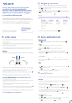
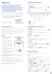
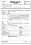
DEMO9S08QE8/4—Lab Tutorials
Taking the Lead in Low Power
LAB
1
Learn How to Use
DEMOQE Toolkit Utilities
About DEMOQE Labs
These labs will show you how to get the
most out of your DEMOQE toolkit. Start
each lab with the board powered ON.
Make sure to use only one utility at a
time, as they share the same USB source.
Familiarize yourself with these buttons:
Start/Continue (F5) button
MCU Change Wizard button
Debug button
AccelerometerDemo running on MC9S08QE8 in data
averaging mode. Bar graph ‘C’ highlights the bus cycles
required to average the last 16 readings of the 3 axes.
The value in the 4th column in the terminal window is the
number of bus cycles in hex.
This lab will show you how to use one of several
graphical utilities in the DEMOQE Toolkit included
with your board. Instructions to download these
utilities to your computer are provided in Step 2 of
the Quick Start Guide (DEMOS08QE8QSG.pdf).
Running the Quick Start Application that came preloaded in the microcontroller’s on-chip flash memory,
we will now use the DEMOQE Logic Analyzer utility.
This PC-based utility graphs the IN0 and IN1 signals
on the board. For convenience, if both J11 jumpers
are installed, IN0 graphs PTC0 activity and IN1 graphs
PTC1 activity. To graph other microcontroller signals,
use wire jumpers from IN0 and IN1 to the respective
signals on the board’s MCU PORT.
1. Make sure that the Quick Start Application is running.
2. Launch DEMOQE Logic Analyzer utility from the start
menu (Programs > P&E DemoQE Toolkit > Utilities >
Logic Analyzer Utility). *See DEMO9S08QE8 User Manual
for details on the Logic Analyzer Utility.
3. In utility, click on the “Open DEMOQE and Graph Pins”
button to begin graphing IN0 and IN1. These signals will
be continually graphed at a sampling rate of 10 kHz.
4. Click button labeled “PTA2.” This will cause a fixed duty
cycle pulse width modulation signal to be output on the PTC0
pin. The PTC0 waveform is shown on analyzer channel IN0.
5. Rotate the potentiometer W1. This will change the duty
cycle of the variable pulse width modulation signal
output on the PTC1 pin. The PTC1 waveform is shown on
analyzer channel IN1.
6. Click on “Close Port” button when finished.
For more information on DEMOQE Toolkit, read the
board user manual (DEMO9S08QE8UM.pdf) included
on DVD under “DEMO9S08QE8 > DEMO9S08QE8
User Manual.” For new and upgraded utilities to the
DEMOQE Toolkit, visit www.pemicro.com/fixedlinks/
demoQEtoolkit.html
LAB
2
Using the Low-Power Modes
This lab will demonstrate usage of three of the
MC9S08QE8’s low-power modes: LPRun, stop2 and
stop3. The lab uses the Terminal Window application
from the DEMOQE Toolkit Utilities to display the
elapsed time since the program started in
hours:minutes:seconds. The software has four modes
of operation:
1. normal run mode
2. low-power run mode (LPRun)
3. stop3 with the external oscillator running
4. stop2 with the external oscillator running
The different modes are selected with the switches
on the DEMOQE board. The display will update every
5 seconds with the elapsed time since the last reset.
In the LPRun mode, the display is not updated, but
the total count is continuously updated. In addition,
pressing the RESET button will toggle the clock gating
open and shut. The MCU current can be measured in
the different modes by replacing the shunt on jumper
J24 (labeled on the bottom of the DEMOQE board)
with a current meter. Lowest power consumption is
achieved by removing jumpers from accelerometer
(J13-J16), potentiometer (J21) and LED circuitry (J9).
For this lab to operate correctly, the IIC pullup jumpers
(J20) must be removed.
1. Open CodeWarrior for Microcontrollers. From Windows start menu you can locate it using the “Programs > Freescale CodeWarrior > CW for Microcontroller V6.x >
CodeWarrior IDE.exe” path.
2. Click on “Load Example Project” from CodeWarrior
startup dialog. If the startup dialog is not shown, it may
be opened from the CodeWarrior menu by clicking “File” and then “Startup Dialog…”.
3. From example projects menu, open tree to select “HCS08 > Evaluation Board Examples > DEMO9S08QE8 > DEMO9S08QE8_Low_Power.”
4. Create a new project name (ex. Lab2), set desired location
and click “Create Project”. This will open the project for
the Low Power application for the DEMO9S08QE8.
5. Launch “Terminal Utility” from the start menu (Programs
> P&E DemoQE Toolkit > Utilities > Terminal Utility). *See DEMO9S08QE8 User Manual for details on the
Terminal Utility.
6. Set port to USB COM and baud rate to 9600.
7. Turn board power switch to OFF position.
8. Board jumpers should all be set to the default settings shown in Quick Start Guide.
9. Turn board power switch to ON position and close debugger window.
10.
Compile and program the MC9S08QE8 with Low Power application by clicking on “Debug”
button, launching Debugger.
11.From Connection Manager menu, select “DEMOQE on
USB1” port and click on “Connect (Reset).”
12.From Erase and Program Flash menu, click on “Yes” to allow
the debugger to mass erase the microcontroller’s on-chip
flash memory and program it with the new application.
13.For the application to run correctly, the MCU cannot be in
debug mode. Therefore, close the Debugger window. Turn
the board power switch OFF, then ON to power cycle the
MCU. The MCU is now running the Low Power application.
14.Bring Terminal Utility to front and click the “Open Serial Port” button.
15.Observe output in Terminal Utility. Count should increase by 5 every 5 seconds.
16.Press and hold button labeled “PTA3” on board to enter
LPRun mode until mode change is reflected in terminal
window. The terminal time updates will cease but the
PTC0 LED will continue to blink. Wait 5 or more seconds.
17.Press and hold button labeled “PTA2” on board to enter
normal run mode until mode change is reflected in
terminal window. The terminal time updates will resume
with accurate total count.
18.Press and hold button labeled “PTD2” on board to enter
stop3 mode until mode change is reflected in terminal
window. The MCU will wake from stop3 mode every 5
seconds and update the total count.
19.Press and hold button labeled “PTD3” on board to enter
stop2 mode until mode change is reflected in terminal
window. The MCU will wake from stop2 mode every 5
seconds and update the total count.
20.To exit from the stop2 mode, hold one of the other
buttons down until the terminal window shows a change
of mode. This may take up to 5 seconds.
21.Click the button labeled “RESET” to toggle the clock
gates open and shut. When the gates are shut, the
normal run mode current will be noticeably lower. You
should not see a significant difference in the other
modes. The RESET button should not be used when the
DEMO is in stop2 mode.
22.Click on “Close Port” button and close Terminal Utility when finished.
LAB
3
Measure Performance of the
MC9S08QE8 with Accelerometer Demo
This lab will highlight the performance capability of the
MC9S08QE8 microcontroller. It will also detail how to
use another one of several software utilities included with
your board to help you in your development. Instructions
to download these utilities to your computer were
provided in Step 2 of the Quick Start Guide.
The accelerometer application reads the X, Y and Z
axes of the 3-axis accelerometer on the DEMOQE
board using the microcontroller’s A/D converter. After any
reset, it outputs the raw values of the accelerometer
data on the microcontroller’s serial communication
interface. Pressing the PTA3 switch outputs a rolling
average of the raw accelerometer data, and pressing
the PTA2 switch outputs a filtered version of the raw
accelerometer data. For this lab to operate correctly,
the IIC pullup jumpers (J20) must be removed.
Setup demo:
1. Open CodeWarrior for Microcontrollers. From Windows start menu, you can locate it using the “Programs > Freescale CodeWarrior > CW for Microcontroller V6.x > CodeWarrior IDE.exe” path.
2. Click on “Load Example Project” from CodeWarrior startup dialog.
3. From example projects menu, open tree to select: “HCS08 > Evaluation Board Examples > DEMO9S08QE8 > DEMO9S08QE8_Accelerometer_Ex.”
4. Create a new project name (ex. Lab3), set desired
location, and click “Create Project.” This will open
the project for the Accelerometer Application for the
MC9S08QE8 microcontroller.
5. Launch Accelerometer Demo utility from the start
menu (Programs > P&E DemoQE Toolkit > Utilities > Accelerometer Demo). *See DEMO9S08QE8 User Manual
for details on the Accelerometer Demo utility.
6. Set port to USB COM and baud rate to 9600.
7. Turn board power switch to OFF position.
8. Board jumpers should all be set to the default settings shown in Quick Start Guide.
9. Turn board power switch to ON position and close
debugger window.
10.
Compile and program the MC9S08QE8 with the Application by clicking on “Debug” button,
launching Debugger.
11.From Connection Manager menu, select “DEMOQE on
USB1” port and click on “Connect (Reset).”
12.From Erase and Program Flash menu, click on “Yes” to allow
the debugger to mass erase the microcontroller’s on-chip
flash memory and program it with the new application.
13.
Click on the “Start/Continue (F5)” button in
debugger to run application.
14.Bring Accelerometer Demo utility to front and click the “Open Serial Port and Start Demo” button.
15.Move board around to demonstrate 3-axis accelerometer.
16.Observe output of raw data in Accelerometer Demo
utility. The data is displayed in hexadecimal format in the
Terminal Window and in graphical form in the bar graph
and Scope windows. The fourth value is the number of
bus cycles for the CPU to process the data.
17.Click button labeled “PTA3” on board to enable data
averaging. Move board.
18.Click button labeled “PTA2” on board to enable data
filtering. Move board.
19.Click on “Close Port” button and close Terminal Utility when finished.
DEMO9S08QE8/4—Lab Tutorials
DEMO9S08QE8/4—Lab Tutorials
Switch
LEDs
Push Buttons
External
Power
Connector
Speaker
Potentiometer
Pemicro
Embedded
Multilink USB
Connector
DC9S08QE8
Daughter Card
RS232 Connector
Accelerometer
Figure 1. DEMOQE baseboard with MC9S08QE8 (8-bit) daughter card.
The DC9S08QE8 daughter card can be used on the DEMOQE128 kit.
Ultra-Low-Power Microcontrollers
Learn More:
DEMO9S08QE8
Lab Tutorials
For more information about
Freescale products, please visit
www.freescale.com/lowpower.
Freescale and the Freescale logo are trademarks or registered trademarks of Freescale
Semiconductor, Inc. in the U.S. and other countries. All other product or service names are the
property of their respective owners. © Freescale Semiconductor, Inc. 2008.
Doc Number: QE8QE4LABSSHEET / REV 1
Agile Number: 926-22168 / REV B
DEMO9S08QE8/4—Lab Tutorials
MCU Port Connector Pinout
Default Jumper Settings
The following is the pinout for the MCU port connector on the DEMOQE board. No connects (n/c) for 32LQFP apply to DC9S08QE8 daughter card.
The following is a list of default jumper settings for DEMOQE board.
The settings listed indicate the “on” (or installed) position.
VDD
1
2
PTA5/IRQ/TPM1CLK /RESET
VSS
3
4
PTA5/IRQ/TPM1CLK/RESET
PTB1/KBI1P5/TxD1/ADP5
5
6
PTA4/ACMP1O/BKGD/MS
PTD0/KBI2P0/SPSCK2
29
30
PTD4/KBI2P4 (n/c for 32 LQFP)
Jumper
InstalledSettings
Jumper
InstalledSettings
2&3
J14
2&3
PTD3/KBI2P3/SS2
31
32
PTD5/KBI2P5 (n/c for 32 LQFP)
J3
PTC2/TPM3CH2
33
34
PTD6/KBI2P6 (n/c for 32 LQFP)
J4
3&4
J15
2&3
1&2
J16
1&2, 3&4, 7&8
PTB0/KBI1P4/RxD1/ADP4
7
8
PTE7/TPM3CLK (n/c for 32 LQFP)
PTC3/TPM3CH3
35
36
PTD7/KBI2P7 (n/c for 32 LQFP)
J5
PTA2/KBI1P2/SDA1/ADP2
9
10
VREFH
PTC4/TPM3CH4/RSTO
37
38
PTC7/TxD2/ACMP2-
J6
2&3
J17
1&2, 3&4
PTA3/KBI1P3/SCL1/ADP3
11
12
VREFL
PTC5/TPM3CH5/ACMPO
39
40
PTC6/RxD2/ACMP2+
J7
2&3
J18
1&2, 3&4
2&3
J19
1&2
1&2, 3&4, 5&6, 7&8, 9&10,
11&12, 13&14, 15&16
J20
1&2, 3&4
J21
1&2, 3&4
J24
1&2
PTC0/TPM3CH0
13
14
PTA0/KBI1P0/TPM1CH0/ADP0/ACMP1+
(n/c for 32 LQFP) PTF2/ADP12
41
42
PTB7/SCL1/EXTAL
J8
PTC1/TPM3CH1
15
16
PTA1/KBI1P1/TPM2CH0/ADP1/ACMP1-
(n/c for 32 LQFP) PTF3/ADP13
43
44
PTB6/SDA1/XTAL
J9
PTB3/KBI1P7/MOSI1/ADP7
17
18
PTF0/ADP10 (n/c for 32 LQFP)
(n/c for 32 LQFP) PTF4/ADP14
45
46
PTG0 (n/c for 32 LQFP)
PTB4/TPM2CH1/MISO1
19
20
PTF1/ADP11 (n/c for 32 LQFP)
(n/c for 32 LQFP) PTF5/ADP15
47
48
PTG1 (n/c for 32 LQFP)
PTB2/KBI1P6/SPSCK1/ADP6
21
22
PTA6/TPM1CH2/ADP8
(n/c for 32 LQFP) PTF6/ADP16
49
50
PTH0 (n/c for 32 LQFP)
PTB5/TPM1CH1/SS1
23
24
PTA7/TPM2CH2/ADP9
(n/c for 32 LQFP) PTF7/ADP17
51
52
PTH1 (n/c for 32 LQFP)
PTD1/KBI2P1/MOSI2
25
26
PTH6/SCL2 (n/c for 32 LQFP)
(n/c for 32 LQFP) PTG2/ADP18
53
54
PTE6 (n/c for 32 LQFP)
PTD2/KBI2P2/MISO2
27
28
PTH7/SDA2 (n/c for 32 LQFP)
(n/c for 32 LQFP) PTG3/ADP19
55
56
NC
J11
1&2, 3&4
J12
1&2, 3&4, 5&6, 7&8
J13
2&3