1
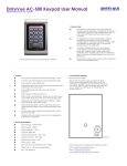
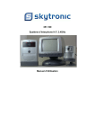
SolarGuard®
Driveway Receiver
User Manual
1. Purpose & Application
1.1. The driveway receiver (buzzer box) is designed to be used in conjunction with a
pair of SolarGuard® which provides a warning of vehicles or pedestrians
entering a designated area.
1.2. The driveway receiver (buzzer box) can receive signals from up to six sets of
SolarGuard®.
1.3. The driveway receiver (buzzer box) has a relay contact to permit connection of
an extension buzzer or flashing light to make the alert more noticeable. The relay
contact turns on and off a 9 volt supply.
1.4. If an alert in several locations is required then an additional driveway receiver
may be used with the same set of SolarGuard®.
1.5. If desired to receive alerts while moving about a site or at a remote location then
the SolarGuard® Auto-Dialler receiver may be used with, or instead of the
driveway receiver (buzzer box) to call any mobile phone or landline phone and
play a short pre-recorded message.
1.6. The driveway receiver (buzzer box) is not designed to receive signals from other
manufacturer’s equipment.
2. Setting up the receiver
2.1. The driveway receiver (buzzer box) must be positioned so that is has a clear
radio path from the SolarGuard®. The radio beam will travel in an essentially
straight line. It will go through trees, windows, non-metallic building walls etc, but
the range will be reduced. The beam will not pass through metal eg corrugated
iron walls of a barn (but through the barns window line of site etc). The beam will
also be blocked by ground contours eg if there is a hill between the receiver and
transmitter. If obstructions are a problem then a wireless repeater may enable
you to get around this problem. Consult your SolarGuard® distributor. In open
space with no obstructions the SolarGuard® beams can be up to 1km (3200
feet) from the driveway receiver (buzzer box).
2.2. The power pack supplied with the driveway receiver (buzzer box) plugs in to the
socket on the back of the receiver.
2.2. The receiver should give three short beeps (“dididi“) when turned on, and the
power LED will glow to show the correct connection.
3. Programming the receiver
3.1. Hold in the set button, on the rear of the receiver, for approximately 3 seconds
until a long beep is heard, then release the button. Generate a signal from the
SolarGuard® beams. - With the SolarGuard® turned on and aligned, break
and generate an alarm.
3.2. The receiver will give two short beeps (didi) when it has successfully learnt the
SolarGuard® code and the LED for that zone will light temporally.
3.3. After the receiver has learnt one code from a set of SolarGuard® beams it is
necessary to repeat steps 3.1 and 3.2 to learn the next code if additional sets of
SolarGuard® are being installed to the receiver.
3.4. If there are already 6 codes in the receiver it will give a succession of 4 short
beeps (didididi,didididi,didididi). The memory must be erased as in section 3.5.
3.5. The driveway alert receiver can only receive signals from up to 6 sets of
SolarGuard®. If you wish to erase a set of SolarGuard® from the receiver,
you must erase the memory and programme in each SolarGuard®. Press the
set key and hold it in for 10 seconds. After 3 seconds a long beep will be herd.
After 10 seconds four short beeps will be herd (didididi). The set button may now
be released. NOTE erasing the memory will clear all programmed sets of
SolarGuard®. If you wish to retain some of them, they will have to be reprogrammed.
3.6. The driveway receiver will retain the learnt sets of SolarGuard® in its memory
even if the power supply is disconnected.
4. Operating of the receiver
4.1. When the driveway alert receives a signal it will sound the internal buzzer for 3
seconds and the LED for the appropriate zone will light until the set button is
pressed or another zone is triggered.
4.2. The normally open (NO) relay will close for 3 seconds, turning on any buzzer or
light connected to it.
4.3. If the zone light is lit pressing the set button will briefly turn of the zone light.
4.4. If no zone light is lit and the set button is pressed briefly the Output Enable light
turn off. The buzzer will no longer sound when a zone is triggered. The relay will
still operate and the zone light will still come on.
4.5. To enable the buzzer press the set button briefly. The Output Enable light will
come on.
5. Connection of extension bells
5.1. The external buzzer or flashing light is connected to the screw terminals on the
front of the receiver. The driveway receiver provides a Normally Open (NO)
contact which closes on activation.
Driveway
Receiver
Relay
Contact
Internal
Power Supply
Driveway alert receiver
can connect an additional
buzzer or flashing light
Typical connection to an external buzzer or flashing light.
The driveway receiver provides 9 volt DC, to the relay contacts to power an external bell
buzzer or light. Maximum current is 200mA.
Polarity of the terminals is shown in the diagram below:
ZONE 1
ZONE 2
ZONE 5
ZONE 6
ZONE 3
ZONE 4
Relay
Output
OUTPUT
ENABLE
Ground
terminal -
Positive
terminal +