1
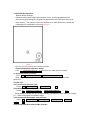
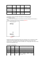
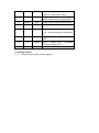
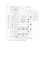
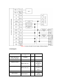
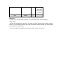
S100EM Metal Password Access Controller
User Manual
Reading carefully before Install and use this manual
1. Product Profile
The product is Contact-less inductive card Metal Password Access Controller,
According to the model, respectively support EM, HID, MIFARE three cards, It is one of the most
advanced stand alone access controller. It uses unique metal exterior design, Dexterity keyboard
panel operation, Built-in high-grade microprocessors, Strong anti-interference ability, Safety and
reliability is extremely high, can provide a powerful security for 2,000 users. It has strong functions,
such as low power consumption, Luminous keyboard, independent passwords, wiegand output, the
output short circuit protection, door magnetic alarm, prevent demolition alarm, exit button, the
doorbell interface, level of security Settings, etc. widely used in home, office, residential area and
other public places.
2. Features
Low power consumption: less than 30mA standby current
Luminous keyboard: the night can also operate keyboard
User capacity: support 2,000 users
Independent password: can use password which irrelevant with the card to
open the door
User modification password: Users can revise the door password
Search speed: charge to open the door time less than 0.1 S.
Output short circuit protection: electric lock or alarm output circuit within 100
μS when shut down automatically output
Wiegand output: With Wiegand output interface,Wg26 card number or Wg4
buttons output
Usable keyboard delete card number: After card is lost, usable keyboard
delete card, Thoroughly eliminate safety lapses
The demolition alarm: Illegal dismantling machine, built-in alarm sound
buzzer
The bell button and interface: key and circuit segregation, external any the
doorbell.
3. Technical parameters
Work Voltage:AC&DC9-28V
Static Current:≤30mA
Reading Range:3~8cm
Capacity: 2000 users
Ambient Temperature:-25℃~60℃
Ambient Humidity:10%~90%
Electricity lock output:≤3A
Alarm output:≤20A
Output short circuit protection time:≤100μS
Open time:0 ~ 99 seconds (adjustable)
Size:120 *80*25mm
4. Administrator operation
Restore factory settings:
Disconnect the power supply open the back cover, use the equipped two feet
short-circuit the inserting pin, plugged into the machine rear Two short circuit seat,
then electrify,The machine "di di" two empress, then take short circuit, namely the
inserting pin for initialization of success. (Figure 1)
Figure 1
Note: restore factory Settings will not delete a user data
Enter administrator operation status:
Press
*
Administrator password
# Administrator the default password: 999999
4.1 Modify administrator password:
0
The new password #
Repeat the new password #
Note: the administrator password for 6 ~ 8 random Numbers, please take
good care.
4.2 Add user:
4.2.1 Continuous increase card:
Press
1
Reading card ,Reading card ,… #
4.2.2 Designated card No increase:
Press 1
Eight card number # , Eight card number # ,… #
Automatically increase, the user ID automatically generated by this machine, the range
is 1 ~ 2000, and search from small to large.
4.2.3 Designated ID No swipe card increase:
Press 1
ID Number #
Reading card , ID Number #
Reading
card ,… #
4.2.4 Designated ID No and card No increase:
Press
Press 1
ID Number # Eight card number # , ID Number # Eight card
number # ,… #
Note: input ID digits for 1-4 digits, The range is 1 ~ 2000, such as 1,01,001,0001 ID
number all expressed 1.
Add card user will automatically generate a default password "1234", but this password
can't open the door, only for a user to change a new password.
4.2.5 Designated ID No and password increase:
Press 1
ID No # password #
ID No # Password # … #
Note: applicable to no card users, password and card unrelated, input digits for four,
but not for "1234"
4.3 Delete user
4.3.1 Delete swipe card
Press 2
Reading card
Reading card … #
4.3.2 Delete Designated card Number:
Press 2
Eight card number # , Eight card number # ,… #
4.3.3 Delete Designated ID Number:
Press 2
ID No # ID No # … #
4.3.4 Delete all:
Press 20000
#
4.4 Door open method setting:
4.4.1 Card open:
Press 3
0
#
4.4.2 Card + Password open:
Press 3
1
#
4.4.3 Card or Password open:(Factory default)
Press 3
2
#
4.5 Unlock time setting:
Press 4
0~99
#
Note: The lock time range "0 to 99 seconds ", the factory default is 5 seconds
4.6 Alarm time setting:
Press 5
0~3
#
Note: The alarm time range "0 to 3 minutes ", the factory default is 1 minute
4.7 Magnetic Alarm Function setting:
4.7.1 Shielding of the function (factory default):
Press 6
0
# 。
4.7.2 Open the function:
Press 6
1
#
Open the function, two possibilities:
4.7.2.1 If you open the door not closed properly, 1 minute, built-in buzzer alarm tone hair
tips, door or turn off automatically after 1 minute.
4.7.2.2 If normal unlock 20 seconds after the doors open, or door is forced open, external
alarm and built-in buzzer alarm at the same time
4.8 Security mode setting
4.8.1 Normal mode (factory default)
Press 7
0
#
4.8.2 Lock mode:
Press 7
1
#
That within ten minutes of continuous brush invalid card or enter the wrong password ten
times, external alarm and built-in buzzer alarm at the same time
5. User operations
5.1 User use card modify password:
Press *
Reading card
Old password #
New password # Repeat the
new password #
5.2 User use ID No modify password
Press *
ID No # Old password #
New password # Repeat the
new password #
Note: applicable to a card or without card users, if the user password is "1234", must
use card to modify
5.3 Card open:
Reading card ,Effective namely open
5.4 Password open:
Press User password # ,Password right namely open
5.5 Card + Password open:
Reading card User password # ,Card and password right namely open
6 Remove alarm operation
6.1 External alarm and built-in buzzer alarm at the same time
SwipeValid card or press Administrator password# ,Can remove alarm。
6.2 Close door alarm tips
Close the door,or swipe card Valid card,or Input administrator password# ,Can
remove alarm
7. Acousto-optic instructions
Operation
state
Red
Light
Green
Light
Standby
Slow
flashing
Off
Buttons
Success
Failure
Buzzer
Di
Off
On
Di-
DiDiDi
Note
Into
programming
On
Off
Set condition
On
On
Exit
programming
Slow
flash
Off
Di-
Unlock
Off
On
Di-
Alarm
Fast
flashing
Off
Alarm
sound
Di-
Indicator is
orange
8 Installation method, lead wire description and Cabling diagram
8.1 Installation method
8.1.1 On the wall of the aperture size machine on the pan is playing well with a hole, or
installed 2 exisiting junction box plus connecting.(Figure 2)
Figure 2
8.1.2 Put the lead wire from Bottom shell of the outlet hole oout, he connection of cable
needed, Unused lines wrapped with insulating tape isolated to prevent short circuit
8.1.3 Finish line, Install the front cover to the back cover, Finally tighten the screws, Fixed
the front cover and back cover.
8.2 Lead wire description
Line
sequence
Marks
Color
Function description
1
BELL_A
Pink
2
BELL_B
Pale blue
3
D0
Green
WG output line D0
4
D1
White
WG output line D1
5
ALARM
Grey
Alarm
negative
connected + 12 v
Doorbell button one end
The doorbell button to the other end
(alarm
positive
6
OPEN
Yellow
Exit button one end(Exit button the
other end connected GND)
7
D_IN
Brown
Magnetic switch one end (magnetic
switch another end connected GND)
8
AC&DC
Red
Power supply 9-28V input (DC input+)
9
AC&DC
Black
Power supply 9-28V input (DC input
-)
10
NO
Blue
Relay normally-on
end(Connected positive electric lock
+)
11
COM
Purple
Relay
GND
12
NC
Orange
Relay
Closed end ( connected
negative electric lock +)
13
GND
Shielding layer
Public end , Connected
Ac input for machines minus
8.3 Cabling diagram
8.3.1 Ordinary power supply Cabling diagram
Figure 3 Ordinary power supply Cabling diagram
8.3.2 Access Control Power Supply Cabling diagram
Figure 4 Access Control Power Supply Cabling diagram
9 Packing list
Name
Model/specificati
on
Quantit
y
Metal Password
access controller
S100EM
1
User manual
S100EM
1
Tapping screws
4
Used for
installation
fixed
4
Used for
installation
fixed
1
Secial
1
Used
between
Φ4mm×28 mm
Stopper
Φ6mm×30 mm
Star screwdriver
Star screws
Φ20mm×60mm
Φ3mm×6mm
Note
the front
cover and
back cover
for a fixed
LED
1N4007
1
Warm Tip:
* Please don't secretly repair machine, if any problem, please return to factory
maintenance.
* Before the installation on the wall, if you want to punch, please check carefully wiring or
line tube, prevent drilling broken wiring etc unnecessary trouble, please use safe glasses
when drilling or fixed line clip.
* If product upgrades, specifications will likely differ, without prior notice.