1
25
Pre-laboratory:
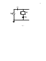
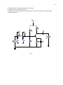
All the preparation parts must be computed before the experiments part. Consider the circuit of
Fig. 1.
Let VCC = 12 V, RC = 6.2 kΩ, RE = 1.8 kΩ, and RL = 2.2 kΩ.
1) Calculate values of R1, R2 so that ICQ ≈ 1 mA and for good bias stability (or RBB =
0.1×(β+1)×RE).
2) Compute the Q-point and the maximum unclipped output voltage with CE included (CE = 100
µF).
3) Repeat 2 if capacitor CE is removed.
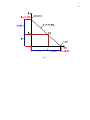
4) With RC, RE and RL the same as what used in 1), re-calculate R1 and R2 so that the operating
point is at the center of the AC load line. Re-calculate the maximum unclipped output with CE
included (CE = 100 µF).
5) Repeat 4 with the bypass capacitor CE removed.
6) Change the value of RC to 3.2 kΩ and re-calculate the DC operating point ICQ. What do you
notice?
You may find the following equations useful:
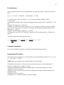
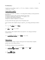
I CQ ≈
VBB − VBE ( on )
V × R2
R × R2
VBB = CC
RBB = 1
V BE ( on ) ≈ 0.7 V
RBB
R1 + R2 ,
R1 + R2 ,
,
+ RE
β
Computer Simulation
Use a circuit simulation program to verify the results found in the preparation.
Experimental Procedure:
The purpose of the experiment is to verify the theoretical and simulation results. Use CB = 1 µF,
CL = 1 µF, and CE = 100 µF.
%OTE: Make sure capacitors are connected with the correct polarity.
1) Build the circuit in Fig.1 with the values you calculated in part (1) of the preparation. If
necessary, re-adjust R1, R2 so that ICQ ≈1 mA.
2) Measure the maximum sinusoidal unclipped output. Set the input frequency to 5 kHz.
3) Repeat (2) with CE removed.
4) Replace R1, R2 with the ones found in the pre-lab preparation part (4) and measure the new
unclipped output.
5) Repeat (4) with CE removed.
6) Change RC to 3.2 kΩ and measure ICQ after the change.