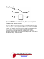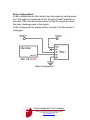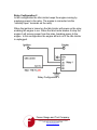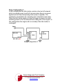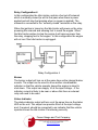
1
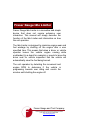
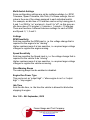
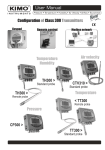
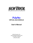
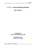
Idle Limiter
User Manual
Fraser Gauge and Tool Company
1352 Harvard Road, Grosse Pointe, Michigan 48230
(313) 516-7151 fax (313) 882-5254
www.frasergauge.com
Neither the whole nor part of the information herein, nor the product described may be adapted or
reproduced in any material form except with the prior written consent of Fraser Gauge.
The product described in this manual is subject to continuous development and improvement. All
information herein of a technical nature, and particulars of the product and its use, are given in good
faith but are liable to change without notice.
All installation, maintenance or service of this product must be carried out by Fraser Gauge or its accredited
agent, and loss or damage caused by installation, maintenance or service which is
carried out by unauthorized personnel will not be accepted.
This manual is intended only to assist the reader in the use of the product, and therefore Fraser Gauge shall
not be liable for any loss or damage whatsoever arising from the use of any information or particular in or
any error of omission from this manual or any incorrect use of this product.
Fraser Gauge welcomes comments or suggestions relating to the product or this manual. All
correspondence should be addressed to:
Customer Service Manager
Fraser Gauge
1352 Harvard Road
Grosse Pointe Park, MI 48230
(313) 516-7151
[email protected]
© 2001-20010 Fraser Gauge
Fraser Gauge and Tool Company
1352 Harvard Road, Grosse Pointe, Michigan 48230
(313) 516-7151 fax (313) 882-5254
www.frasergauge.com
Table of Contents
IdleLimiter................................................................... 1
User Interface ............................................................. 2
“Engine Run” LED ......................................................................... 2
Status LED..................................................................................... 2
Buzzer............................................................................................ 2
Wiring Instructions .................................................... 4
Input Cable .................................................................................... 4
Ignition / Speed / RPM................................................................... 4
Engine Run .................................................................................... 4
Buzzer............................................................................................ 9
Status Indicator.............................................................................. 10
Settings....................................................................... 11
SW1 ............................................................................................... 11
SW2 ............................................................................................... 11
Multi-Switch Settings ..................................................................... 12
Settings.......................................................................................... 13
Revision History......................................................... 14
Rev 1.00 – 8th September, 200914
Fraser
Fraser Gauge and Tool Company
1352 Harvard Road, Grosse Pointe, Michigan 48230
(313) 516-7151 fax (313) 882-5254
www.frasergauge.com
Fraser Gauge Idle Limiter
Fraser Gauge Idle Limiter is a innovative and simple
device that does not require extensive user
interaction. This manual will simply describe the
function of the Idle Limiter and information on how
the unit operates.
The Idle Limiter is designed to minimize engine wear and
fuel wastage by shutting off the engine after a user
specified time. This means that when a driver or vehicle
operator leaves the vehicle engine running while
unattended (in a depot for example) or needs to leave the
driver seat for vehicle inspection that the vehicle will
automatically save the fuel being burned.
The unit operates by detecting the movement and
engine RPM to determine if the vehicle is
progressing towards over idling and counts the
minutes until shutting the engine off.
Fraser Gauge and Tool Company
1352 Harvard Road, Grosse Pointe, Michigan 48230
(313) 516-7151 fax (313) 882-5254
www.frasergauge.com
User Interface
“Engine Run” LED
This LED matchs the “Engine Run” status (i.e. LED on if the engine is
allowed to run; LED off if the engine is being prevented from running).
The only exception is that the LED is always off when ignition is off
(similar to the “Engine Run” output always being low in this state).
Status LED
The status LED on the box represents the current state of the unit
and matches the External Status Output.
The various LED flash patterns are:
State
Ignition Off
Engine Off
Pattern
On for 500ms, Off for 500ms
On for 200ms, Off for 100ms, On for
200ms, Off for 500ms
Moving
On solid
Idling
Every 20 seconds flash the number
of minutes till shutdown (200ms
on/off for each minute left). N.B. At ≥
50 minutes left, this will look like
continuous flashing (200ms on/off).
Idle Stopped
On for 800ms, Off for 200ms
Engine Stopped On for 200ms, Off for 800ms
Buzzer
If the setting “Give Warning Beeps” is enabled, the buzzer will warn
the driver of the impending shutdown.
The internal and external buzzers sound at the same time.
With 2 minutes to go till shutdown, the unit beeps for 1 second.
Fraser Gauge and Tool Company
1352 Harvard Road, Grosse Pointe, Michigan 48230
(313) 516-7151 fax (313) 882-5254
www.frasergauge.com
With 1 minute to go till shutdown, the unit beeps twice (1second on,
500ms off, 1 second on).
With 45 seconds to go till shutdown, the unit beeps three times
(1second on, 500ms off, 1 second on, 500ms off, 1 second on).
With 30 seconds to go till shutdown, the unit beeps four times
(1second on, 500ms off, 1 second on, 500ms off, 1 second on,
500ms off, 1 second on).
With 15 seconds to go, the unit beeps constantly (1 second on,
500ms off) until the engine stops.
When the engine stops the unit will give a long beep
(5 seconds).
Fraser Gauge and Tool Company
1352 Harvard Road, Grosse Pointe, Michigan 48230
(313) 516-7151 fax (313) 882-5254
www.frasergauge.com
Wiring Instructions
Input Cable
The table below shows the input cable colors:
Input
Ground
Power
Color
Comment
Green Connects to the vehicle ground
Red
Connects to the vehicle supply.
It is designed for 12 & 24V vehicles.
Ignition
Yellow Connects to a signal that is on
with the ignition – this is how the
Idle Limiter knows the engine should be
running.
RPM
Blue
Connects to a RPM signal
EngineRun
Black Max 1A, same voltage as “power”
Buzzer
Brown Max 1A, same voltage as “power”
Status Indicator Purple Max 40mA, same voltage as “power”
Speed
White Connects to a Speed signal
Ignition / Speed / RPM
These signals must be connected for the unit to operate correctly.
The voltage sensitivity of the speed/RPM signals can be configured
(see “Settings” chapter) to accommodate different types of sensors.
The ignition input must be connected to at least 10V when the ignition
switch is on. The unit will not operate correctly if the ignition input is
not connected.
Engine Run
The Engine Run output is designed to power a relay which will control
the engine. It is not designed to power the engine directly. When the
Ignition input is “off” power to this output will be removed, regardless
of how it is configured. This is done to reduce the drain on the vehicle
battery (since leaving a relay on all the time would draw more current)
and to extend the life of the relay.
Fraser Gauge and Tool Company
1352 Harvard Road, Grosse Pointe, Michigan 48230
(313) 516-7151 fax (313) 882-5254
www.frasergauge.com
Relay Terminals
Figure 1
Terminals 85/86 are the coil for the relay. When power is applied to
these terminals the relay switches.
Terminal 30 is a common terminal for the switched signal. When the
relay coil power is removed, terminal 30 is connected to terminal 87a
(called the “normally closed” terminal because it is closed when there
is no power). When relay coil power is applied terminal 30 is
connected to terminal 87 (called the “normally open” terminal
because it is open when there is no power Relay can be configured in
at least four ways, as shown below.
Fraser Gauge and Tool Company
1352 Harvard Road, Grosse Pointe, Michigan 48230
(313) 516-7151 fax (313) 882-5254
www.frasergauge.com
Relay Configuration 1
In this configuration the Idle Limiter stops the engine by cutting power
to it. The engine is connected via the “normally closed” terminals on
the relay. When the Idle Limiter wishes to stop the engine it powers
the relay, breaking power to the engine.
In this configuration the engine will run normally if the Idle Limiter is
unplugged.
Relay Configuration 1
Fraser Gauge and Tool Company
1352 Harvard Road, Grosse Pointe, Michigan 48230
(313) 516-7151 fax (313) 882-5254
www.frasergauge.com
Relay Configuration 2
In this configuration the Idle Limiter keeps the engine running by
supplying power to the relay. The engine is connected via the
“normally open” terminals on the relay.
When the ignition is turned on the Idle Limiter will power up the relay,
enabling the engine to run. When the Idle Limiter wishes to stop the
engine it will remove power from the relay, breaking power to the
engine. In this configuration the engine will not run if the Idle Limiter
is unplugged.
Relay Configuration 2
Fraser Gauge and Tool Company
1352 Harvard Road, Grosse Pointe, Michigan 48230
(313) 516-7151 fax (313) 882-5254
www.frasergauge.com
Relay Configuration 3
In this configuration the Idle Limiter controls a fuel cut-off solenoid
which is normally open (ie will let fuel pass when there is no power
applied and will stop fuel passing when power is applied). The
solenoid is connected to the “normally open” terminals on the relay.
When the Idle Limiter wishes to stop the engine it powers the relay,
switching power to the fuel solenoid and cutting fuel to the engine. In
this configuration the engine will run normally if the Idle Limiter is
unplugged.
Relay Configuration 3
Fraser Gauge and Tool Company
1352 Harvard Road, Grosse Pointe, Michigan 48230
(313) 516-7151 fax (313) 882-5254
www.frasergauge.com
Relay Configuration 4
In this configuration the Idle Limiter controls a fuel cut-off solenoid
which is normally closed (ie will let fuel pass when there is power
applied and will stop fuel passing when no power is applied). The
solenoid is connected to the “normally closed” terminals on the relay.
When the ignition is turned on the Idle Limiter will power up the relay,
powering the solenoid and allowing fuel to reach the engine. When
the Idle Limiter wishes to stop the engine it will remove power from
the relay, stopping fuel to the engine. In this configuration the engine
will not run if the Idle Limiter is unplugged.
Relay Configuration 4
Buzzer
The buzzer output will turn on at the same time as the internal buzzer
sounds. The output can be used to drive another visual/audible
indicator so that the vehicle operator knows the engine is about to
shut down. This output can supply 1A at the input voltage – if the
indicator current is likely to be near or above this then an external
relay will need to be used.
Status Indicator
The status indicator output will turn on at the same time as the status
LED on the unit. This output can provide 40mA at the input voltage
and, if required, should be connected to an indicator that the vehicle
operator knows the Idle Limiter if functioning correctly.
Fraser Gauge and Tool Company
1352 Harvard Road, Grosse Pointe, Michigan 48230
(313) 516-7151 fax (313) 882-5254
www.frasergauge.com
Settings
Settings are configured by opening the unit and adjusting the
switches located on the circuit board. In order to configure the engine
cut-off delay you must use SW1 and SW2.
SW1
PIN
4
3
2
1
SW2
PIN
8
7
6
5
4
3
2
1
Setting
RPM Tolerance
RPM Tolerance
Speed Tolerance
Speed Tolerance
If Switch is On
Tolerance setting +2
Tolerance setting +1
Tolerance setting +2
Tolerance setting +1
Setting
If Switch is On
Give Warning Beeps
Warning beeps enabled
Engine Run Power Type Output high=allow
engine to run
Idle Time Idle time
+32 minutes
Idle Time Idle time
+16 minutes
Idle Time Idle time
+8 minutes
Idle Time Idle time
+4 minutes
Idle Time Idle time
+2 minutes
Idle Time Idle time
+1 minute
Open the unit by unscrewing the four screws on the rear of the unit.
The circuit board is attached to the underside of the top of the unit.
The circuit board looks like the following:
Fraser Gauge and Tool Company
1352 Harvard Road, Grosse Pointe, Michigan 48230
(313) 516-7151 fax (313) 882-5254
www.frasergauge.com
Multi-Switch Settings
Some configuration settings are set by multiple switches (i.e. RPM
Tolerance, Speed Tolerance, Idle Time). For these settings, the set
value is the sum of the values assigned to each individual switch.
For example, an idle time of 19 minutes can be set by turning pins 5,
2 and 1 on SW2 to “on” and pins 6, 4 and 3 to “off”, as this gives an
idle time value of 16 minutes + 2 minutes + 1 minute = 19 minutes.
There are therefore 4 different tolerance settings for each of RPM
and Speed: 0, 1, 2 and 3.
Settings
RPM Sensitivity
Sets how sensitive the RPM input is, i.e. the voltage change that is
required for the engine to be “running”.
Higher numbers mean it is less sensitive, i.e. requires larger voltage
changes to register the engine running.
Speed Sensitivity
Sets how sensitive the Speed input is, i.e. the voltage change that is
required for the vehicle to be “moving”.
Higher numbers mean it is less sensitive, i.e. requires larger voltage
changes to register the vehicle as moving.
Give Warning Beeps
The warning beeps can be enabled or disabled.
Engine Run Power Type
This can be set as “output high” = “allow engine to run” or “output
high” = “stop engine”.
Idle Time
Sets the idle time, i.e. the time the vehicle is allowed to idle before
stopping its engine.
Revision History
Rev 1.00 – 8th September, 2009
Fraser Gauge and Tool Company
1352 Harvard Road, Grosse Pointe, Michigan 48230
(313) 516-7151 fax (313) 882-5254
www.frasergauge.com