1
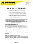
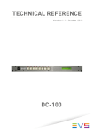
12843 Foothill Blvd. Suite C Sylmar, California 91342 V: 818.898.3380 F: 818.898.3360 [email protected] Introducing the AnyWhere Interface Switch The Missing Link for User Interfaces 1 to 4 pushbutton switches with built-in LCD display GPI Control- Turn ON, Turn OFF, Toggle Ethernet Control- UDP, TCP/IP No Programming Required No Scripting Language Simple to Configure From a Web Browser Powerful Control Switch Press GPI On/Off Switch Press Transmit Ethernet Command Switch Press Control 2 GPIs Transmit 3 Ethernet Commands Switch Press #1 Control GPI #3 Transmit 2 Ethernet Commands Switch Press #2 Control GPI #2 Wait 2 seconds Transmit 3 Ethernet Commands Display status and user prompts on switch face Create a 10 step sequence, 5 actions per step Execute one step per switch press. Execute 5 actions per switch press. Mounts in duplex or quad electrical box Power over Ethernet(POE) or optional external power supply Page 1 of 18 TABLE OF CONTENTS 1. ANYWHERE INTERFACE SWITCH MODELS...............................................3 2. INSTALLATION & CONFIGURATION ...........................................................4 A. INSTALLATION ...................................................................................4 B. GPO CONNECTORS ...........................................................................4 C. CONFIGURATION ...............................................................................4 D. POWER UP ..........................................................................................5 3. SYSTEM CONFIGURATION WEB PAGE ......................................................6 4. GPO CONFIGURATION WEB PAGE.............................................................7 5. REMOTE DEVICE LIST CONFIGURATION WEB PAGE ..............................8 6. SWITCH- STEPS/ ACTIONS CONFIGURATION WEB PAGE......................9 7. SWITCH CONFIGURATION WEB PAGE.....................................................10 8. TALLY CONFIGURATION WEB PAGE .......................................................13 9. EXT TALLY COMMANDS DESCRIPTION ...................................................16 10. DNF CONTROLS LIMITED WARRANTY .....................................................18 Revision History Version 1.0 Original Version 1.1 Added description of EXT Tally Commands Version 1.2 Added depth of electrical junction box to specifications Page 2 of 18 1. ANYWHERE INTERFACE SWITCH MODELS AnyWhere Interface Switch Specifications MODELS 2. AIS-10 AIS-20 AIS-24 AIS-44 Pushbutton Switches 1 2 2 4 LCD display mounted on switch face 1 2 2 4 GPO Outputs Isolated, dry, relay contact closures 0 0 4 4 Ethernet Port RJ45 10baseT 1 1 1 1 Power Size fits in standard electrical junction box with 2.25 inch depth Power over Ethernet (POE) Or, optional external power, 5.4 watts duplex junction box duplex junction box AIS-44 quad junction box AIS-24 AIS-20 AIS-10 Page 3 of 18 quad junction box INSTALLATION & CONFIGURATION A. INSTALLATION 1. Connect Ethernet RJ45 male connector to the Ethernet connector on the rear 2. Power using Power Over Ethernet(POE) . Power is provided through Ethernet RJ45. No additional connections are required. Or, power using optional external power supply. Connect power supply to power connector on the rear of AnyWhere Interface Switch 3. On models AIS-24 and AIS-44, wire 2-pin Phoenix-style connector male and connect to female connector on rear. 4. Mount AnyWhere Interface Switch in electrical junction box. B. GPO CONNECTORS Four GPO connectors mounted on rear of unit. Pin# Description 1 Relay common 2 Relay Normally Open C. CONFIGURATION Use the GPO Actions web page to configure GPO operation. Use the Serial Port Configuration web page to configure the serial port. Use the Remote Device Assignment web page to configure Ethernet connections. POWER The AnyWhere Interface Box is powered from an Ethernet switcher/ router that supports Power Over Ethernet (POE), or from an optional external power supply. The AIB requires 12 volts DC at 2 amps from an external power supply and 13 Watts from POE switch. An external power supply may be purchased from DNF Controls. DEFAULT ETHERNET CONFIGURATION IP Address: Subnet Mask: Gateway: 192.168.10.217 255.255.255.0 192.168.10.1 RESET TO FACTORY DEFAULTS Press and hold rear mounted switch for 10 seconds to reset the IP address, subnet mask, Gateway, and configuration to factory defaults. Page 4 of 18 CONFIGURATION The AnyWhere Interface Switch(AIS) is configured using a standard web browser (Internet Explorer, Firefox, and Chrome). Enter the AIS’s IP address in the Address/ URL bar, typically located at the top of the web browser page, to access the AIS’s Home Page. Use the links on the left side of the Home Page to access the desired configuration web page. All configuration settings are saved in non-volatile storage in the AIS. Settings are retained when power is removed from the AIS. Settings may be uploaded to a computer as a configuration file (.dnf) for archiving. Configuration files may be downloaded from a computer into the AIS to restore a saved configuration. A configuration file contains all of the AIS’s configurations except IP address, subnet mask, and gateway address. The AIS does not support partial configuration upload or download. The configuration file is a not a text formatted file. It can not be viewed or modified with a text editor. To access the System Configuration web page, use the following log-on when prompted. User name: dnfuser Password: controls D. POWER UP At power up, when power is applied to the AnyWhere Interface Switch(AIS), from POE or external power supply, the product Model Number will be displayed on switch #1 for approximately 5 seconds. After 5 seconds, the Tally Mode settings will determine which text legends and switch backlight color will be displayed. (See TALLY Configuration Web Page section.) During the time that the Model Number is displayed, press any switch to view the Ethernet IP address, Subnet Mask, Gateway address, and MAC address settings. On a two switch or four switch unit, “VIEW MODE” will be displayed on switch #2 or #3. In VIEW MODE: Press any switch to view the IP Address. Press any switch to view the Subnet Mask. Press any switch to view the Gateway Address. Press any switch to view the MAC address. Press any switch to exit VIEW MODE. The AIS will automatically exit VIEW MODE after 30 seconds when no switch has been pressed. Page 5 of 18 3. SYSTEM CONFIGURATION Web Page Software Upgrade: Use this link to install the P1 upgrade file provided by DNF Controls Web Upgrade: Use this link to install the Web pages’ upgrade file provided by DNF Controls Save Configuration Use this link to save the AIS’s current configuration to a configuration file on a to PC: computer. The web browser will prompt for file name and directory. The file extension must be ‘dnf’. Restore Configuration Use this link to download a configuration file from your computer into the AIS. from PC: The web browser will prompt for directory and configuration file name. The file extension must be ‘dnf’. Set Configuration Use this link to reset all AIS configurations to factory defaults. This will NOT to Defaults: change the IP address, subnet mask or gateway address. The AIS will reboot automatically. Enter Label: Enter 32 character label which is only displayed on the Home Page to identify the AIS. Enter the new IP Enter the new IP address, Gateway, and Subnet Mask. Click on Save Config settings below: to save the new entries. The AIS will reboot automatically. Page 6 of 18 4. GPO Configuration Web Page GPO Label Enter any 15 characters or symbols. For user convenience only. User Defined ON State RELAY OPEN: The relay is OPEN when the GPO is ON. The relay is CLOSED when the GPO is OFF. RELAY CLOSED: The relay is CLOSED when the GPO is ON. The relay is OPEN when the GPO is OFF (Factory Default). User Defined MOMENTARY: The GPO turns ON, waits for the MOMENTARY ON TIME to expire, and then automatically turns OFF. Operating Mode LATCH: The GPO turns ON and stays ON. The GPO turns OFF and stays OFF. Momentary For MOMENTARY operating mode only. ON duration for Momentary GPO. Drop down menu ON Time settable from 0.01 sec to 2.0 sec. Page 7 of 18 5. REMOTE DEVICE LIST Configuration Web Page The AnyWhere Interface Switch (AIS) will transmit commands to and receive commands from the Remote Devices listed on this web page. If a Remote Device is not listed on this page, the AIS will not send commands to that device, nor will it accept commands from that device. Remote Device Label Enter any 32 characters. This label is for user convenience only. Device Type Select EXT Tally ONLY for a Remote Device that will be using DNF’s EXT Tally protocol to control AIS key legend and key color. Otherwise, set to ‘------‘. Connection Type Select UDP or TCP/IP Connection Mode For TCP/IP Only Client Transmit: Establish connection to remote device. Transmit command. Disconnect from remote device. Client Transmit/Receive: Establish connection to remote device. Maintain connection to remote device. Server Receive/Transmit: Accept connection from client. Only client at assigned IP Address can connect The client is responsible for maintaining connection. Server Mode only, AnyWhere Interface Switch listens on the following ports: Port 50001 for connection from Remote Device 1 Port 50002 for connection from Remote Device 2 Port 50003 for connection from Remote Device 3 Port 50004 for connection from Remote Device 4 UDP Attempts For UDP Connection Type only. The number of times that the message will be sent separated by 10milliseconds. Since UDP does not provide guaranteed delivery, UDP Attempts provides more than one transmit attempt to deliver the message. IP Address Client or Destination IP address Port Number Destination port number for transmit commands Connection Status For TCP/IP Connection Types only Page 8 of 18 6. SWITCH- Steps/ Actions Configuration Web Page Each switch supports a sequence of 10 switch presses and 5 actions for each switch press. After power up, the first switch press will cause the Step #1 actions to be executed. The second switch press will cause the Step #2 actions to be executed. The third switch press will cause the Step #3 actions to be executed. After executing the Step 10 actions, the next switch press will cause the Step #1 actions to be executed. All Actions are executed in the order displayed. An Action must complete before the next Action will be executed. This configuration pages sets the actual number of Steps that will be used and the number of actions per step that will be used. Steps Select 1 – 10. Every switch press will advance to the next step number per the MODE selection. Actions Select 1 – 5. Each switch press will execute the indicated number of user assigned actions. Link Select None, Group A or Group B. On each Group A switch’s switch press, all Group A switches will go to that switch’s Step number. On each Group B switch’s switch press, all Group B switches will go to that switch’s Step number. All grouped keys will be on the same Step number at all times. Switches set to NONE will operate independently from all other switches. Mode Execute Next Step: Execute the current switch Step number and then advance to the next Step number. After executing the last Step number, go to the first Step number. Execute Previous Step: Execute the current switch Step number and then go to the previous Step number. After executing the first Step number, go to the last Step number. Next Step Execute: Go to the next Step number and then execute its actions. If on the last Step number, go to the first Step number. Previous Step Execute: Go to the previous Step number and then execute its actions. If on the first Step number, go to the last Step number. Page 9 of 18 7. SWITCH Configuration Web Page A Step’s Actions are executed in the order displayed. An Action must complete before the next Action will be executed. Each Step Action will execute in the order displayed until all actions for that Step have completed. [Remainder of page left blank] Page 10 of 18 Step Number Identifies the 1 – 10 Steps displayed. Set the number of Steps and Actions by using the Steps/ Actions Configuration at the top of the web page. Device For each Action, select LOCAL or a specific Remote Device to affect Control For Local Device: Action Do Nothing No action executed Local GPO ON Turn ON selected GPO Local GPO OFF Turn OFF selected GPO Local GPO Toggle Toggle the selected GPO. If ON, then turn it OFF. If OFF, then turn it ON. Goto Step #1 The switch goes back to its first step Continue to Next Step After executing the Actions for the current Step, execute the Actions for the next Step. Set Switch #1 to Step# Set Switch #1 to the indicated Step number Set Switch #2 to Step# Set Switch #2 to the indicated Step number Set Switch #3 to Step# Set Switch #3 to the indicated Step number Set Switch #4 to Step# Set Switch #4 to the indicated Step number Pause Wait 0.25 seconds to 10 seconds before executing the next Action For Remote Device: Transmit Command Data Transmit the user entered ASCII/ Hex command For Local Device: Local GPO ON GPO# Local GPO OFF GPO# Local GPO Toggle GPO# Set Switch #1 to Step# Step Number Set Switch #2 to Step# Step Number Set Switch #3 to Step# Step Number Set Switch #4 to Step# Step Number Pause Wait time: 0.25 seconds to 10 seconds Page 11 of 18 ASCII/ Hex An ASCII/HEX Command is 1 - 200 characters in length. Command Use %xy to enter HEX value. x and y are values 0 - 9 or A- F. Two characters must follow %. Use %WTttt to add WAIT. Transmit command characters to the left of %WT. Wait ttt time, 001 - 999 milliseconds. Transmit next part of command or rest of command. NOTE-%WT is only an approximate wait time. NOTE- Spaces between characters are NOT transmitted. Use %20 to transmit a space character. Use %22 to transmit a single quote character ("). Use %27 to transmit a double quote character ('). [Remainder of page left blank] Page 12 of 18 8. TALLY Configuration Web Page Tally Mode Fixed Key legend and color are static Follow The key legend and color defined for the Switch current Step will be displayed on the face of the switch Follow Local The key legend and color assigned for OFF GPO will be displayed when the indicated GPO is OFF. The key legend and color assigned for ON will be displayed with then GPO is ON. EXT Tally A Remote Device will control the key Commands legend and color using the DNF’s EXT Tally protocol. (On the Remote Device List web page, set Device Type for this Remote Device to “EXT Tally”.) See “EXT Tally Commands” section for command format. Page 13 of 18 Text Static legend displayed on face of switch Font Font size: Small- 18 Characters Normal- 8 Characters Big- 3 Characters 6 characters per row x 3 rows 4 characters per row x 2 rows 3 characters per row x 1 row Color Switch backlight color: Dark, Red, Green, Amber Flashing, Blinking or Solid Source GPO# to follow OFF Text legend displayed on face of switch when GPO is OFF OFF Font Font size: Small- 18 Characters Normal- 8 Characters Big- 3 Characters 6 characters per row x 3 rows 4 characters per row x 2 rows 3 characters per row x 1 row OFF Color Switch backlight color: Dark, Red, Green, Amber Flashing, Blinking or Solid ON Text legend displayed on face of switch when GPO is ON ON Font Font size: Small- 18 Characters Normal- 8 Characters Big- 3 Characters 6 characters per row x 3 rows 4 characters per row x 2 rows 3 characters per row x 1 row ON Color Switch backlight color: Dark, Red, Green, Amber Flashing, Blinking or Solid Page 14 of 18 Step# Switch Step Number Text legend displayed on face of switch Font Font size: Small- 18 Characters Normal- 8 Characters Big- 3 Characters 6 characters per row x 3 rows 4 characters per row x 2 rows 3 characters per row x 1 row Color Switch backlight color: Dark, Red, Green, Amber Flashing, Blinking or Solid Page 15 of 18 9. EXT Tally Commands Description The External Tally Commands control the text and backlight displayed on the AnyWhere Interface Switch’s LCD display face. The backlight is the color of the face of the switch─ Red, Green, Amber, or Dark. Command Format: [ + # + cmd + = + key# + data + ] NOTE: ‘+’ has been added between command elements for ease of reading. Do not include ‘+’ in the actual command. The ‘[‘ and ‘]’ mark the beginning and end of the command text, respectively. The ‘#’ immediately follows ‘[‘. Replace ‘cmd’ with: T followed by the font size and then text to be displayed on the switch face C to set control the color of the switch’s backlight The ‘=’ immediately follows ‘cmd’. Replace ‘key#’ with the key number to be controlled: 1, 2, 3, or 4 Replace ‘data’ with the desired information. See examples below. COMMAND: (use the first letter only) (C)olor of switch backlight (T)ext displayed on switch face BACKLIGHT COLOR: 0 = SOLID_DARK 1 = SOLID RED 2 = SOLID GREEN 3 = SOLID AMBER 4 = BLINKING RED FAST 5 = BLINKING RED SLOW 6 = BLINKING GREEN FAST 7 = BLINKING GREEN SLOW 8 = BLINKING AMBER FAST 9 = BLINKING AMBER SLOW Example #1: Set switch #1 backlight to SOLID RED Command is [ #C=11] Example #2: Set switch #3 backlight to BLINKING AMBER FAST Command is [ #C=38] Page 16 of 18 TEXT A maximum of 18 characters may be displayed on the switch face, 3 rows of 6 characters, using SMALL font size. Any number of characters less than 18 may be displayed. A maximum of 8 characters may be displayed on the switch face, 2 rows of 4 characters, using NORMAL font size. Any number of characters less than 8 may be displayed. A maximum of 3 characters may be displayed on the switch face, 1 row of 3 characters, using BIG font size. Any number of characters less than 3 may be displayed. Font Size: 0 = Small font- 6 characters x 3 rows 1 = Normal font- 4 characters x 2 rows 2= Big Font- 3 characters x 1 row Example #3: Set switch #2 font size to Normal, 2 rows of 4 characters, and display “Test1234” on the face of the switch. Command is [ #T=21Test1234] Example #4: Set switch #1 font size to Big, 1 row of 3 characters, and display “BIG” on the face of the switch. Command is [ #T=12BIG] Example #5: Set switch #4 font size to Small, 3 rows of 6 characters, and display “abcdefghijklmnopqr” on the face of the switch. Command is [ #T=40abcdefghijklmnopqr] Example #6: Set switch #3 font size to Small, 3 rows of 6 characters, and display “TEST” on the face of the switch. Command is [ #T=30TEST] Example #7: Set switch #1 font size to Small, 3 rows of 6 characters, and display “TEST” on the second row. Add 6 spaces after the font size to force TEST to the second row. Command is [ #T=10 TEST] Page 17 of 18 10. DNF CONTROLS LIMITED WARRANTY DNF Controls warrants its product to be free from defects in material and workmanship for a period of one (1) year from the date of sale to the original purchaser from DNF Controls. In order to enforce the rights under this warranty, the customer must first contact DNF’s Customer Support Department to afford the opportunity of identifying and fixing the problem without sending the unit in for repair. If DNF’s Customer Support Department cannot fix the problem, the customer will be issued a Returned Merchandise Authorization number (RMA). The customer will then ship the defective product prepaid to DNF Controls with the RMA number clearly indicated on the customer’s shipping document. The merchandise is to be shipped to: DNF Controls 12843 Foothill Blvd., Suite C Sylmar, CA 91342 USA Failure to obtain a proper RMA number prior to returning the product may result in the return not being accepted, or in a charge for the required repair. DNF Controls, at its option, will repair or replace the defective unit. DNF Controls will return the unit prepaid to the customer. The method of shipment is at the discretion of DNF Controls, principally UPS Ground for shipments within the United States of America. Shipments to international customers will be sent via air. Should a customer require the product to be returned in a more expeditious manner, the return shipment will be billed to their freight account. This warranty will be considered null and void if accident, misuse, abuse, improper line voltage, fire, water, lightning or other acts of God damaged the product. All repair parts are to be supplied by DNF Controls, either directly or through its authorized dealer network. Similarly, any repair work not performed by either DNF Controls or its authorized dealer may void the warranty. After the warranty period has expired, DNF Controls offers repair services at prices listed in the DNF Controls Price List. DNF Controls reserves the right to refuse repair of any unit outside the warranty period that is deemed non-repairable. DNF Controls shall not be liable for direct, indirect, incidental, consequential or other types of damage resulting from the use of the product. Page 18 of 18