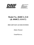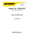
1
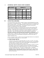
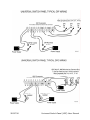
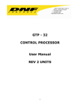
12843 Foothill Blvd.,
Suite D
Sylmar, CA 91342
818 898 3380 voice
818 898 3360 fax
www.dnfcontrols.com
Universal Switch Panel
User Manual
Rev 1.0
NOTES:
TABLE OF CONTENT
REVISION HISTORY.................................................................................................. 2
I.
UNIVERSAL SWITCH PANEL MODEL NUMBERS.................................................... 3
II.
OPERATION OVERVIEW................................................................................... 3
A. FRONT PANEL SWITCH ............................................................................. 3
B. REAR PANEL GPO .................................................................................... 4
C. FRONT PANEL TALLY ................................................................................ 4
III.
SWITCH OPERATING MODE ............................................................................. 5
IV.
GPO OPERATING MODE................................................................................... 5
A. MOMENTARY Operation ............................................................................ 5
B. FOLLOW Operation .................................................................................. 5
C. LATCH Operation ..................................................................................... 5
D. FLIP FLOP MODE OF OPERATION ............................................................... 5
E. Group (Radio group) Operation.................................................................. 6
F. alarm operation....................................................................................... 6
G. GPO Control By Switch on a Remote USP .................................................... 6
H. GPO Control By GTP-32 or DC20 Event ....................................................... 6
V.
TALLY OPERATING MODE ................................................................................ 6
A. Follow GPO Operation .............................................................................. 6
B. External (GPI) Operation .......................................................................... 6
C. Remote Operation ................................................................................... 7
VI.
ALARM MODE ................................................................................................ 7
VII.
EVENT NOTIFICATION MODE ........................................................................... 7
1.
GETTING STARTED…… ............................................................. 8
UNIVERSAL SWITCH PANEL CONFIGURATION .................................................... 9
A. REMOTE DEVICE ASSIGNMENT .................................................................. 9
B. SWITCH ASSIGNMENT ............................................................................11
C. TALLY ASSIGNMENT................................................................................13
D. ALARM ASSIGNMENT ..............................................................................15
E. EVENT NOTIFICATION CONFIGURATION ....................................................17
F. GPO CONFIGURATION .............................................................................19
G. GPI CONFIGURATION ..............................................................................21
H. SYSTEM CONFIGURATION........................................................................23
3.
FIRMWARE UPGRADES.................................................................................. 25
4.
SPECIFICATIONS ......................................................................................... 26
A. FRONT VIEW..........................................................................................27
B. REAR VIEW............................................................................................27
5.
CONNECTOR PINOUT DIAGRAM...................................................................... 29
6.
APPLICATION NOTES .................................................................................... 31
A. GPI.......................................................................................................31
B. GPO......................................................................................................33
DNF CONTROLS LIMITED WARRANTY........................................................................ 36
2.
Universal Switch Panel (USP) User Manual
1 OF 36
REVISION HISTORY
102407
First Draft.
121407
Added application notes.
022008
Updated rear view drawing.
050708
Add alarm and event notification functions
052108
First release, 1.0
2 OF 36
Universal Switch Panel (USP) User Manual
I.
UNIVERSAL SWITCH PANEL MODEL NUMBERS
Model Number
II.
Number of:
Front Panel
Switches
GPI
GPO
USP-8
8
8
8
USP-8A
8
16
16
USP-16
16
16
16
USP-EM-8
None
8
8
USP-EM-16
None
16
16
OPERATION OVERVIEW
The Universal Switch Panel (USP) is a panel of generic switches designed to emulate
the operation of mechanical switches. The mechanical switch feel is provided by the
USP’s front panel switch. The mechanical switch’s contact closure is provided by the
USP’s general purpose outputs (GPO). The mechanical switch’s internal tally
indicator is provided by the USP switch’s backlight.
Unlike mechanical switches, the operating mode of the front panel switches, GPO
contact closures, and tally can be easily configured by the user for their specific
application. Additionally, ON text and OFF text can be displayed on the face of the
USP switch. Each switch can be configured to operate standalone or as part of a
radio group. Also, each GPO contact closure can be configured to operate as
Momentary, Latching, or interlocked (commonly referred to as “radio group”). And,
each tally can be configured to be Always ON, Always OFF, follow the state of the
contact closure, or follow the state of an external device. Additionally, the ON and
OFF tally for each tally can be individually configured to be Dark, Red, Green, or
Amber, and Flash or not.
Unlike a mechanical switch, a switch on the Universal Switch Panel can be configured
to control a GPO on another USP, turn it ON and OFF.
A. FRONT PANEL SWITCH
Pressing a switch causes its associated GPO to turn ON or turn OFF. The switch
contacts, represented by the GPO, operate according to the user configured GPO
operating mode. The switch can control a GPO located on the same panel or it
can control a GPO located on another, remote, USP.
Each switch used on the USP front panel has an LCD display mounted on its face.
The display is used to show an ON tally text label and an OFF tally text label.
Each switch display can be configured by the user to show 1 row of 3 characters,
2 rows of 4 characters each, or 3 rows of 6 characters each. The display
backlight functions as the tally, replacing an internal bulb or led. The user can
individually configure each backlight to turn red, green, amber, or dark to show
an ON or OFF tally. Additionally, the backlight can be configured to flash in its
ON or OFF tally state.
Universal Switch Panel (USP) User Manual
3 OF 36
B. REAR PANEL GPO
Each GPO contact closure is a single pole, single throw relay. The GPO connector
on the rear of the USP provides access to the relay contacts, Common and
Normally Open (N.O.), providing isolation between outputs. A common bus (CB)
is also available to tie one side of the relays to a common ground or voltage.
The operating mode of each GPO can be individually configured to one of the
following modes:
1) MOMENTARY MODE
The GPO will turn on when its controlling switch is pressed and then
automatically turn off after a preset time. The GPO will not change state
when the switch is released.
2) LATCHING MODE
The GPO will change state when the switch is pressed. If the GPO was OFF, it
will turn ON. If it was ON, it will turn OFF. The GPO will not change state
when the switch is released.
3) FOLLOW MODE
The GPO will turn ON when the controlling switch is pressed and immediately
turn OFF when the switch is released.
4) FLIP FLOP MODE
The FLIP FLOP is a special case of a GPO Radio Group. One switch controls
two GPOs. One GPO is ON while the other GPO is OFF. When the switch is
pressed the GPOs will alternate states, the previously ON GPO will turn OFF
and the previoulsy OFF GPO will turn ON.
5) GROUP MODE
There are 8 GPO groups, RG1 through RG8. A GPO can be a member of only
one group at a time. The group operates in a manner similar to interlocking
mechanical switches― when one switch is pressed, all of the other switches
are released. When any member of the group is turned ON, all of the other
members are immediately and automatically turned OFF. Only one member
of a group can be ON at any time.
C. FRONT PANEL TALLY
The tally is the LCD backlight on the face of the switch. For Tally ON and Tally
OFF states, each tally can be individually configured to be dark, red, green,
amber, flashing red, flashing green, or flashing amber.
The tally can be configured to show the current state of the controlled GPO or
show the current state of a General Purpose Input (GPI) on the rear of the USP.
The GPI is used to monitor the status of an external device. There are 16 GPIs
available on two rear panel connectors. The tally can be assigned to only one
GPI at a time. When the GPI is ON, the tally will turn ON. When the GPI is OFF,
the tally will turn OFF.
4 OF 36
Universal Switch Panel (USP) User Manual
III.
SWITCH OPERATING MODE
Each switch can be assigned to control one or more GPOs through the USP’s SWITCH
ASSIGNMENT web page. When the switch is pressed, each controlled GPO changes
state according to its individual user configured operating mode. (See GPO
OPERATING MODE section of this document). When the switch is released, only
those GPOs configured for FOLLOW Operating Mode will change state.
IV.
GPO OPERATING MODE
Each GPO can be configured by the user to operate according to one of the following
operating modes. Only one operating mode can be assigned to a GPO at any time.
The assignment of a new operating mode automatically overrides the previous
operating mode assignment. All GPO configurations are done from the USP’s GPO
page.
A. MOMENTARY OPERATION
When the controlling switch is pressed, the GPO will immediately turn on and
start its ON Time timer. When the user configured time period has elapsed, the
GPO will automatically turn OFF regardless of the state of the controlling switch.
If the controlling switch is held pressed after the elapsed time or quickly released
before the elapse time has expired, the GPO will only turn OFF when the user
configured ON Time has elapsed. The controlling switch must be released and
then re-pressed before the GPO will turn ON again.
B. FOLLOW OPERATION
When the controlling switch is pressed, the GPO will immediately turn ON. When
the controlling switch is released, the GPO will immediately turn OFF. If the
controlling switch is held pressed, the GPO will stay ON while the switch is being
held.
C. LATCH OPERATION
When the controlling switch is pressed, the GPO will immediately change state.
If the GPO was ON, it will turn OFF. If the GPO was OFF, it will turn ON. The
GPO will not change state when the controlling switch is released. When the
switch is released, the GPO will remain in its last state.
D. FLIP FLOP MODE OF OPERATION
The FLIP FLOP is a special case of a GPO Radio Group. One switch controls two
GPOs. When the switch is pressed and the current status is ON, then the 2nd
GPO will be turned ON and the 1st GPO will be turned OFF. When the switch is
pressed and the current status is OFF, then the 1st GPO will be turned ON and the
2nd GPO will be turned OFF. The current status can be the state of the 1st GPO
(lowest number) or it can be the state of the primary GPI (lowest number).
The GPOs can be configured as LATCH or MOMENTARY. The FLIP FLOP operation
will be configured on a GPO by GPO basis in the GPO Assignment Table. The
drop down selection of GPO operations will include 8 FLIP FLOP selections― FF1,
FF2, FF3, FF4, FF5, FF6, FF7, FF8 ― on a USP-16 and 4 FLIP FLOP selections on a
USP-8. Only two GPOs can be assigned to a specific FLIP FLOP. The FLIP FLOP
operation is defined for GPOs co-located in the same unit. It is NOT currently
defined or supported for GPOs across multiple USP units.
Universal Switch Panel (USP) User Manual
5 OF 36
E. GROUP (RADIO GROUP) OPERATION
The GPO Group operates like a radio group of interlocked switches. Pressing one
switch causes the other switches to automatically release. Only one switch will
remain pressed at any time.
A GPO can belong to one and only one GPO Group. More than one GPO Group
can exist with each group made up of other GPOs. When a GPO is assigned to a
new GPO Group, it is automatically removed from its previous group.
Only one member of a GPO Group can be ON at any time. When a GPO member
is turned ON, all of the other members are immediately turned off. The GPO will
stay on until another member of the group is turned on. With the exception of
powering on the USP, at least one GPO from the GPO group will be turned on.
F. ALARM OPERATION
The GPO can be used to indicate the presence of an alarm condition, either active
or not cleared alarm. The GPO will turn ON when any alarm is active or has not
been cleared. It will turn OFF only when all alarms have been cleared.
G. GPO CONTROL BY SWITCH ON A REMOTE USP
The GPO can be controlled by a switch on a remote Universal Switch Panel in
addition to being controlled by a switch on the same panel. The GPO will
operate according to its user configured Operating Mode whenever the local or
remote switch is pressed and released.
H. GPO CONTROL BY GTP-32 OR DC20 EVENT
The GPO can be controlled by a GTP-32 or DC20 event― GPI or Combinatorial.
It will operate according to its user configured Operating Mode as if a local switch
had been pressed or released.
V.
TALLY OPERATING MODE
The tally is the LCD backlight on the face of the front panel switch. It will be dark,
red, green, amber, flashing red, flashing green, or flashing amber, as configured by
the user on the USP’s Tally Configuration web page. There are two tally
configurations, one configuration for an ON tally and another configuration for an OFF
tally. All tally configurations are done from the USP’s Tally web page.
A. FOLLOW GPO OPERATION
The tally follows the state of the GPO. The tally is ON when the GPO is turned
ON and OFF when the GPO is turned off. The tally follows the state of the GPO
regardless of the operating mode of the GPO.
B. EXTERNAL (GPI) OPERATION
The tally can follow the state of an external device, like a downstream keyer,
through an external GPI. The USP has 8 or 16 GPI Inputs, located on the rear of
the unit. Each GPI is an opto-isolated input, providing electrical isolation
between the external device and the USP. The external GPI can be assigned to
control the tally on a switch. Only one GPI can be assigned to control a switch’s
tally. When a new GPI is assigned to control a tally, the previous assignment is
deleted. One GPI can be assigned to control more than one tally. The tally will
turn ON when the controlling GPI is ON and turn OFF when the GPI is OFF.
6 OF 36
Universal Switch Panel (USP) User Manual
C. REMOTE OPERATION
A tally can be configured to be controlled by a GPO on a remote Universal Switch
Panel. Similar to the Follow GPO Operation, the tally will turn ON when the
remote GPO is ON and turn OFF when the remote GPO is OFF.
VI.
ALARM MODE
The Tally Alarm mode of operation allows multiple tally sources― Local GPIs,
Remote USP GPIs, Remote USP GPOs, GTP-32 Events, and DC20 Events― to be
combined into an Alarm Group to control a specific tally (LCD display). Eight Alarm
Groups are supported. Each Alarm Group can contain any combination of tally
sources. The tally sources within a group are prioritized by the user. When
refreshed after a change, the Alarm Assignment Table will display the table in order
of Alarm Group and by Priority within the Alarm Group.
When a tally source turns ON, it is considered alarmed. If the tally source has the
higher priority of alarmed sources within its group, its alarm indicator (ON tally
configuration) will be reflected on the switch LCD display― ON text, ON font, ON
color. The user must press the associated switch (part of LCD display) to clear the
displayed alarm. If the tally source is still ON, the LCD display will continue to show
the tally source’s alarm indicator.
The LCD display will always show the alarm indicator of the higher priority alarmed
tally source that is ON. Alarms from ON tally sources will be prioritized over alarms
from tally sources that have turned OFF. If there are no alarms with ON tally
sources, then the higher priority alarm of the alarms with tally sources that have
turned OFF will be displayed on the LCD. When the alarm is cleared, by pressing
the switch, the new higher priority alarmed tally source will be reflected on the LCD
display. When there is no alarmed tally source in the Alarm Group, the LCD display
will reflect the assigned OFF tally configuration.
When the higher priority alarmed tally source is ON, the LCD display will flash. When
the higher priority alarmed tally source is OFF, the LCD display will stop flashing and
turn on solid. This behavior is the same for LATCH and TOGGLE style GPI tally
sources.
The “Source” column in the TALLY ASSIGNMENT TABLE is used to select Normal or
Alarm mode of tally operation, as well as the Alarm Group number (1-8) assigned to
the tally.
A switch configured for Alarm Tally may also be configured to control a local or
remote GPO.
Any GPO configured for Alarm mode will turn ON when any alarm is active and has
not been cleared by pressing the appropriate switch. The GPO will turn OFF only
when all alarms have been cleared. The GPO will not distinguish between alarm
groups. More than one GPO can be configured for Alarm mode of operation.
VII.
EVENT NOTIFICATION MODE
The Event Notification mode of operation allows local GPI and GPO events to be sent
to remote USP and GTP-32 units. Remote USPs can use the event notification to turn
on/off front panel tally indicators. Remote GTP-32s can use the event notification in
the Event Monitor Table and in Combinatorial Event Definitions.
Universal Switch Panel (USP) User Manual
7 OF 36
1.
GETTING STARTED……
A. Set the IP Address, Subnet Mask, and Gateway Address for your facility.
(See Section 2H)
B. For Standalone Operation
1)
Configure the front panel switches
(See Section 2B, Switch Assignment)
2)
Configure the front panel tallies
(See Section 2C, Tally Assignment)
3)
To use Alarm Mode, configure the alarm tallies
(See Section 2D, Alarm Assignment)
4)
Configure the GPOs
(See Section 2F, GPO Configuration)
5)
Configure the GPIs
(See Section 2G, GPI Configuration)
C. To Operate with Remote USPs, GTP-32 GPI Tally Processors, DC20 Device
Controllers, and Other Devices
1)
Create the Remote Device List
(See Section 2A, Remote Device Assignment)
2)
Create the Event Notification List
(See Section 2E, Event Notification Configuration)
3)
Configure the front panel switches
(See Section 2B, Switch Assignment)
4)
Configure the front panel tallies
(See Section 2C, Tally Assignment)
5)
To use Alarm Mode, configure the alarm tallies
(See Section 2D, Alarm Assignment)
6)
Configure the GPOs
(See Section 2F, GPO Configuration)
7)
Configure the GPIs
(See Section 2G, GPI Configuration)
8 OF 36
Universal Switch Panel (USP) User Manual
2.
UNIVERSAL SWITCH PANEL CONFIGURATION
The Universal Switch Panel is configured using an off-the-shelf web browser such as
Internet Explorer, Netscape, Fire Fox, or other commonly available browser. Using a
web browser running on a computer, enter the USP’s IP address to connect to the USP’s
web server to view and modify configuration web pages.
The default IP address is:
192.168.10.217
The default Gateway is:
0.0.0.0
The default Mask is:
255.255.255.0
HOME Page
A. REMOTE DEVICE ASSIGNMENT
Use this page to identify the remote Universal Switch Panels, GTP-32 GPI
Tally Processors, or other devices that the local USP will communicate
with. If the USP will operate standalone, this page may be left blank.
Remote Device Assignment Table Parameters
Parameters
Description
Device
Description
Enter a unique device description/ identifier, up to 32 characters in length,
that clearly identifies the remote device. This description/ identifier will
appear in the remote device list that is used on the other configuration
pages.
IP Address
Enter the IP Address for the remote device.
Heartbeat Rate
A heartbeat is sent to the remote device to confirm that it is alive. If the
remote device does not respond to three sequential heartbeats, the USP
will show a communication error.
Select a heartbeat time period. For local LAN, use a small value. For WAN
or internet use a larger value.
Universal Switch Panel (USP) User Manual
9 OF 36
1) CLICK ON THE REMOTE DEVICE ASSIGNMENT BUTTON. THE REMOTE DEVICE
ASSIGNMENT PAGE WILL BE DISPLAYED.
2) Click in the DEVICE Description field and enter a unique description/
identifier, up to 32 characters in length. This description/ identifier will
appear in the remote device list that is used on the other configuration pages.
3) Click in the IP ADDRESS field and enter the IP Address for this device.
4) Click on the down arrow in the Heartbeat Rate column and select the number
of seconds between heartbeats. For local LAN, use a small value. For WAN
or internet use a larger value.
5) Repeat steps 2) thru 4) for each remote device that the USP will communicate
with.
6) Click on the Save button to save changes. Changes will take effect
immediately after saving.
OR,
Click on any other page button to exit without saving changes.
NOTE- To clear a remote device assignment, set the IP address to 0.0.0. and
delete the Device Description.
10 OF 36
Universal Switch Panel (USP) User Manual
B. SWITCH ASSIGNMENT
Use this page to assign a function (action) to each of the the USP’s front
panel switches. If the front panel switches will not be used, this page
may be left blank.
Switch Assignment Table Parameters
Parameter
Description
Switch
Select the desired switch number. One switch can be configured to support
more than one function. A total of 40 switch assignments are supported.
Remote Device
Select the remote device to notify when the front panel switch is pressed or
released. (Only active when TYPE is not LOCAL)
Local:
Type
Control GPO on this USP
Remote USP:
Control GPO on remote USP
GTP32/DC20:
Send switch ‘pressed’ or ‘released’ notification to remote
GTP32 or DC20
Radio Group
Not used at this time. See GPO Configuration- Operating Mode for
configuring Radio Groups.
GPO
Assign GPO controlled by switch.
ENABLE
SWITCH
Assign one of the front panel switches as the ENABLE switch. All switch
presses will be ignored until the ENABLE switch is first pressed and held.
DISABLE ALL
SWITCHES
Disable all switches. Use USP as a tally annunciator panel only.
1)
Click on the Switch Assignment Button. The Switch Assignment Page will be
displayed.
2)
Click on the drop down arrow in each column to view the list of available
options/ values. Select the desired option/ value by clicking on it.
3)
Select the switch number in the Switch column.
Universal Switch Panel (USP) User Manual
11 OF 36
4)
Select the TYPE of device to be controlled in the Type column.
5)
If REMOTE USP or GTP32/DC20 was selected in the TYPE column, select the
Device Description in the Remote Device column. This is the remote device
controlled by the front panel switch.
6)
Select the GPO (local or remote), in the GPO column, that will be controlled
by the front panel switch. A switch can control more than one GPO. Repeat
steps 2 – 5 for each GPO using the same switch number. When TYPE =
GTP32/DC20, GPO selection is not available.
7)
Repeat steps 2 - 5 for each switch assignment.
8)
Assign an ENABLE switch by selecting a switch number in the ENABLE
SWITCH box. Select NONE, if no ENABLE switch is required.
9)
Disable all front panel switches by clicking on the DISABLE ALL SWITCHES
check box.
10) Click on the Save button to save changes. Changes will take effect
immediately after saving.
OR,
Click on any other page button to exit without saving changes.
12 OF 36
Universal Switch Panel (USP) User Manual
C. TALLY ASSIGNMENT
Use this page to assign operating mode, text legend, font size, and tally
color to each front panel switch. (This page is not available on USP-EM.)
Tally Assignment Table Parameters
Parameter
Mode
Alarm
ON Text
OFF Text
Description
STANDARD: Switch tally controlled by one GPI or GPO
ALARM: Switch tally controlled by more than one GPIs
If MODE= ALARM, select alarm group that will control switch tally
Text displayed when Tally state is ON.
Text: Up to 18 ASCII characters (See ON Font selection below).
Text displayed when Tally state is OFF.
Text: Up to 18 ASCII characters (See OFF Font selection below).
SMALL: Display 3 rows of 6 characters each. (Display 1st 18 characters)
ON Font
NORMAL: Display 2 rows of 4 characters each. (Display 1st 8 characters)
BIG: Display 1 row of 3 characters. (Display 1st 3 characters)
SMALL: Display 3 rows of 6 characters each. (Display 1st 18 characters)
OFF Font
NORMAL: Display 2 rows of 4 characters each. (Display 1st 8 characters)
BIG: Display 1 row of 3 characters. (Display 1st 3 characters)
ON Color
Dark, Red, Green, Amber, Flashing Red, Flashing Green, Flashing Amber
OFF Color
Dark, Red, Green, Amber, Flashing Red, Flashing Green, Flashing Amber
Tally Source
Remote Device
Event Label
LOCAL: Always ON, Always OFF, Follow GPO, GPI-1 through GPI-16.
REMOTE: Remote USP GPI, Remote USP GPO, GTP-32/DC20 event.
Select Remote Device Description from list.
(Only available when Tally Source= REMOTE).
GTP-32 or DC20 Event Label. Must be an exact match of GTP or DC20
event label. (Only available when Tally Source= GTP32/DC20).
Universal Switch Panel (USP) User Manual
13 OF 36
1)
Click on the Tally Assignment Button. The Tally Assignment Page will be
displayed. (USP-16 Tally Assignment page shown.)
2)
Click on the drop down arrow in each column to view the list of available
options/ values. Select the desired option/ value by clicking on it.
3)
Click in the ON Text field and enter the text that will appear on the front
panel switch face when the tally is on. (Not required for Alarm mode.)
4)
Click in the OFF Text field and enter the text that will appear on the switch
face during the tally off state. (Required for Alarm mode.)
5)
Click in the ON Font column and select the font size used by ON Text.
(Not required for Alarm mode.)
6)
Click in the OFF Font column and select the font size used by OFF Text.
(Required for Alarm mode.)
7)
Click in the ON Color column and select the ON Text backlight color.
(Not required for Alarm mode)
8)
Click in the OFF Color column and select the OFF Text backlight color.
(Required for Alarm mode.)
9)
Click in the Source Type column and select the source type.
(Not required for Alarm mode)
10) Click in the Source column and select the tally source.
(Not required for Alarm mode)
11) Click in the Remote Device column and select the Remote Device Description
for the remote device. (Only available if Source Type= REMOTE.)
12) Click in the Event Label column and enter the GTP-32 or DC20 Event Label.
Label spelling must match event label on the remote GTP-32/DC20. (Only
available if SOURCE= GTP32/DC20.)
13) Click in the Mode column and select Tally Mode.
14) Repeat steps 3 – 13 to configure each switch tally.
14 OF 36
Universal Switch Panel (USP) User Manual
15) Click on the Save button to save changes. Changes will take effect
immediately after saving.
OR,
Click on any other page button to exit without saving changes.
D. ALARM ASSIGNMENT
Use this page to create alarm groups for Tally Alarm Mode. A total of 32
tallies may be assigned to alarm groups. If Tally Alarm Mode is not used,
this page may be left blank. (This page is not available on USP-EM.)
Alarm Assignment Table Parameters
Parameter
Description
Alarm #
Alarm Group 1 thru 8
Priority
Alarm priority within group, 1 thru 8. Highest= 1
Source Type
Select tally source type:
Local GPI, Remote GPI, Remote GPO, or GTP32/DC20 Event
Remote
Device
Select Remote Device Description from list.
Source Value
Select GPI or GPO number (1 thru 16).
If Source Type= GTP32/DC20, selection not available.
Label
GTP32/DC20 Event Label. Event Label spelling must match the event label
on the remote GTP-32/DC20. (Only available if Source Type= GTP32/DC20.)
ON Text
Text displayed when tally source is ON.
Text: Up to 18 ASCII characters (See ON Font selection below).
ON Font
SMALL: Display 3 rows of 6 characters each. (Display 1st 18 characters)
NORMAL: Display 2 rows of 4 characters each. (Display 1st 8 characters)
BIG: Display 1 row of 3 characters. (Display 1st 3 characters)
ON Color
Dark, Red, Green, or Amber (Flash and Blink not available)
Universal Switch Panel (USP) User Manual
15 OF 36
1)
Click on the Alarm Assignment Button. The Alarm Assignment Page will be
displayed.
2)
Click on the drop down arrow in each column to view the list of available
options/ values. Select the desired option/ value by clicking on it.
3)
Click in the Alarm# column and select the alarm group number for this tally.
4)
Click in the Priority column and select the priority, within the alarm group, for
this tally.
5)
Click in the Source Type column and select the tally source.
6)
For Source Type= Local GPI:
Click in the Source Value column and select the GPI or GPO to tally.
OR, for Source Type= Remote GPI, Remote GPO:
a) Click in the Remote Device column and select the Remote Device
Description for the remote device to tally.
b) Click in the Source Value column and select the GPI or GPO to tally.
OR, for Source Type= GTP32/DC20:
a) Click in the Remote Device column and select the Remote Device
Description for the remote device to tally.
b) Click in the Label column and enter the GTP-32 or DC20 event label.
Event Label spelling must match the event label on the remote GTP32/DC20.
7)
Click in the ON Text field and enter the text that will appear on the front
panel switch face when the tally is on.
8)
Click in the ON Color column and select the ON Text backlight color.
9)
Repeat steps 3 – 8 for each tally assigned to an alarm group. A total of 32
tallies can be assigned to alarm groups.
16 OF 36
Universal Switch Panel (USP) User Manual
10) Click on the Save button to save changes. Changes will take effect
immediately after saving.
OR,
Click on any other page button to exit without saving changes.
E. EVENT NOTIFICATION CONFIGURATION
Use this page to send GPI and GPO events (turn on/ turn off) to remote
Universal Switch Panels, GTP-32s, DC20s, and other devices. If the USP
does not provide GPI status or GPO event notification to a remote device,
this page may be left blank.
Event Notification Table Parameters
Parameter
Description
GPIO
Select the GPI or GPO event (turn on or turn off) that will be
sent to a remote USP, GTP-32, DC20, or other device. A total
of 32 EVENT NOTIFICATIONS ARE SUPPORTED.
Remote Device Select the Remote Device Description for the device to which
the event notification is sent.
1) Click on the Event Notification button. The Event Notification configuration
page will be displayed.
Universal Switch Panel (USP) User Manual
17 OF 36
2) Click on the drop down arrow in each column to view the list of available
options/ values. Select the desired option/ value by clicking on it.
3) Click in the GPIO column and select the GPI status or GPO event to be sent to
the remote device.
4) Click in the Remote Device column and select the Remote Device Description
for the remote device to which the event notification will be sent. One GPI or
GPO can be sent to more than one remote device. Add one line for each
remote device and use the same GPI or GPO.
5) Repeat steps 2 - 4 for each GPI or GPO event notification.
6) Click on the Save button to save changes. Changes will take effect
immediately after saving.
OR,
Click on any other page button to exit without saving changes.
18 OF 36
Universal Switch Panel (USP) User Manual
F. GPO CONFIGURATION
Use this page to configure the operation of the local GPOs. If the GPOs
are not used, this page may be left blank.
GPO Configuration Table Parameters
Parameter
Description
User Defined
RELAY OPEN: When the GPO is ON, the relay is OPEN. When the
GPO is OFF, the relay is CLOSED.
ON State
RELAY CLOSED: When the GPO is ON the relay is CLOSED. When
the GPO is OFF, the relay is OPEN (Factory Default).
Operating
Mode
MOMENTARY:
The GPO turns ON, waits for the MOMENTARY ON TIME to
expire, and then automatically turns OFF.
LATCH:
The GPO turns ON and stays ON. The GPO turns OFF and stays
OFF.
FOLLOW:
The GPO follows the switch. The GPO turns ON when the
controlling switch is held pressed and immediately turns OFF
when the controlling switch is released.
ALARM:
The GPO turns ON when any alarm is active or has not been
cleared. It will turn OFF only when all alarms have been
cleared.
GPO GROUP (Radio Groups RG1 – RG8):
Only one GPO in a GPO Group can be ON at any time. When a
GPO is turned ON, all of the other GPOs in the group are
immediately turned off.
FLIP-FLOP (LatchFF1–LatchFF8 & MomentaryFF1–Momentary FF8):
Only two GPOs can be assigned to one Flip-Flop group. Like a
GPO Radio Group, when one GPO turns ON the other
automatically turns OFF.
LATCHFF: The GPO turns ON and stays ON. The GPO turns OFF
and stays OFF.
MOMENTARYFF: The GPO turns ON, waits for the MOMENTARY
ON TIME to expire, and then automatically turns
OFF.
Momentary
ON Time
For MOMENTARY operating mode only. ON duration for Momentary
GPO. Settable from 0.01 sec to 2.0 sec.
Universal Switch Panel (USP) User Manual
19 OF 36
1) Click on the GPOs button. The GPO Configuration page will be displayed.
The USP-16, USP-8A, and USP-EM-16 will display 16 GPOs. The USP-8 will
display 8 GPOs.
2) Click on the drop down arrow in each column to view the list of available
options/ values. Select the desired option/ value by clicking on it.
3) Click in the User Defined ON State column and select the desired ON state of
the GPO.
4) Click in the Operating Mode column and select the operating mode for the
GPO.
5) If Operation Mode= Momentary or MomentaryFF, click in the Momentary ON
Time column and select the ON duration for the GPO. This is the amount of
time the GPO will stay on before automatically turning OFF. (The selected
time is multiplied by 10 milliseconds to compute the actual ON time.)
6) Repeat steps 3 - 5 to configure each GPO.
7) Click on the Save button to save changes. Changes will take effect
immediately after saving.
OR,
Click on any other page button to exit without saving changes.
20 OF 36
Universal Switch Panel (USP) User Manual
G. GPI CONFIGURATION
Use this page to configure the operation of the GPIs. If the GPIs are not
used, this page may be left blank.
GPI Configuration Table Parameters
Parameter
Description
User Defined ON State
OPTO ON: The GPI is ON when the opto-isolator (GPI input) is ON
(energized). The GPI is OFF when the opto-isolator is
OFF (de-energized).
OPTO OFF: The GPI is ON when the opto-isolator (GPI input) is
OFF (de-energized). The GPI is OFF when the optoisolator is ON (energized).
User Defined ON Mode
LATCHED: The external tally (GPI Input) turns ON and stays ON.
The external tally turns OFF and stays OFF.
TOGGLE: The external tally turns ON for a short time and then
turns off and stays off. The GPI state toggles (ON Î
OFF or OFF Î ON) each time the opto-isolator turns ON.
Debounce Time
Mapped to Tally
The time period that the external tally (GPI Input) must remain on
to be detected as ON. (The selected time is multiplied by 10
milliseconds to compute the actual Debounce time.)
The column is read-only and shows the current switch tally
assignment for each GPI.
Universal Switch Panel (USP) User Manual
21 OF 36
1) Click on the GPIs button. The GPI Configuration page will be displayed.
The USP-16, USP-8A, and USP-EM-16 will display 16 GPIs. The USP-8 will
display 8 GPIs.
2) Click on the drop down arrow in each column to view the list of available
options/ values. Select the desired option/ value by clicking on it.
3) Click in the User Defined ON State column and select the ON state for the
GPI.
4) Click in the User Defined ON Mode column and select the operating mode for
the GPI.
5) Click in the Debounce column and select the debounce time for this GPI. (The
selected time is multiplied by 10 milliseconds to compute the actual Debounce
time.) Debounce time is the time period that the GPI must remain on to be
detected as ON.
6) Repeat steps 3 - 5 to configure each GPI.
7) Click on the Save button to save changes. Changes will take effect
immediately after saving.
OR,
Click on any other page button to exit without saving changes.
22 OF 36
Universal Switch Panel (USP) User Manual
H. SYSTEM CONFIGURATION
Use this page to change the IP Address, Subnet Mask, and Gateway
Address for the USP. Also, use this page to install firmware upgrades.
The default IP address is: 192.168.10.217
The default Gateway is:
0.0.0.0
The default Mask is:
255.255.255.0
1) CHANGE IP SETTINGS
a) Click on the System Configuration button. The AUTHENTICATION
WINDOW (log on window) will be displayed.
b) Click in the User Name field and enter the user name, “dnfuser”, using
all lowercase letters. Do not enter the double quotes (“ “).
c) Click in the Password field and enter the password, “controls”, using all
lowercase letters. Do not enter the double quotes (“ “).
d) Click on the OK button to complete the authentication (log on)
process. The System Configuration page will be displayed.
OR
Click on the Cancel button to exit and not access the System
Configuration page.
Universal Switch Panel (USP) User Manual
23 OF 36
e) Click in the IP Address field and enter the new IP address.
f) Click in the Gateway field and enter the new Gateway.
g) Click in the Subnet Mask field and enter the new Mask.
h) Click on the Save button to save changes. Changes will take effect
immediately after saving.
OR,
Click on any other page button to exit without saving changes.
2) RESET CONFIGURATION TO FACTORY DEFAULTS
a) Click on the SET CONFIGURATION TO DEFAULTS button. The SET TO
DEFAULTS page will be displayed.
b) Click on the Set to Defaults button, to restore the factory default
settings.
OR
Click any other button to not change any settings.
24 OF 36
Universal Switch Panel (USP) User Manual
3.
FIRMWARE UPGRADES
The Universal Switch Panel is designed to allow field upgrades of its software quickly
and easily through a web browser. Please follow the firmware upgrade directions
provided with the software file.
Universal Switch Panel (USP) User Manual
25 OF 36
4.
SPECIFICATIONS
Housing Size
1 RU 19-inch Rack mount
Switches
USP-8: 8 LCD style keys
USP-16: 16 LCD style keys
Switch Action
Programmable- Momentary, Latched, Toggle or Radio Group
Momentary On Time
Programmable- 10ms increments
Switch Output
Isolated contact closure or closure to common buss
Radio Groups
Programmable1 or more groups
2 or more switches per group
Switch Legend
Programmable1 Row of 3 characters
2 Rows of 4 characters each
3 Rows of 6 characters each
Tally
Programmable- Internal (switch state)
External Tally Input
Wet or dry
or External (GPI/opto-isolator input)
26 OF 36
Universal Switch Panel (USP) User Manual
A. FRONT VIEW
USP-16
USP-8
USP-EM
B. REAR VIEW
Universal Switch Panel (USP) User Manual
27 OF 36
28 OF 36
Universal Switch Panel (USP) User Manual
5.
CONNECTOR PINOUT DIAGRAM
Universal Switch Panel (USP) User Manual
29 OF 36
30 OF 36
Universal Switch Panel (USP) User Manual
6.
APPLICATION NOTES
A. GPI
1)
USER DEFINED "ON" STATE.
a) Opto ON
When the unit is going to be used with the external source supplying
power, the "ON" state should be defined as "opto ON". Since the opto
circuit is
normally off, it
will be turned
on by the
application of
the external
signal.
Connection of power = ON
No connection of power = OFF
b) Opto OFF
When the unit is wired using the internal power supply (wet mode), the
"ON" state should be defined as "opto
OFF. Since the internal power supply is
supplying power to the opto circuit we
are acctually turning it on, but since we
want it to be off, we need to tell the GPI
state to be off. When we short the GPI
input to ground by the external signal,
we will be turning it off, but then we
invert the signal and make the GPI state
be ON. So an external short to ground
will cause the GPI state to turn ON.
Connection to ground = ON
No connection to ground = OFF
2)
USER DEFINED "ON" MODE.
a) Latched
The user defined "ON" mode as LATCHED, means that the GPI state will
follow the external signal. When the signal is
'on' the GPI state is on, when the signal is 'off'
the GPI state is off. This, of course, is
conditioned by the above "user defined 'ON'
state".
The GPI state follows the input signal
Universal Switch Panel (USP) User Manual
31 OF 36
b) Toggle
The user defined "ON" mode as TOGGLE,
means that the GPI state will change from
OFF to ON or from ON to OFF depending
on the last condition of the GPI state.
This, of course, is conditioned by the
above "user defined 'ON' state".
If the GPI state was 'off' and the input signal turns to 'on', the GPI state
will change to 'on'.
If the GPI state was 'on' and the input signal turns to 'on', the GPI state
will change to 'off'.
3)
DEBOUNCE TIME (ADJUSTABLE FROM 10MS TO 2000MS IN 10MS
INCREMENTS).
The "debounce time" setting causes the input signal to not affect the
GPI state unless it is 'on' longer than the
debounce time. If the input signal is not on
for the duration of the debounce time the
input signal is considered to be not valid.
For short time settings, this acts as a spike filter, to not allow spurious
signals to affect the GPI state.
When the time setting is made long, this can
be used to delay the input signal, as long as
the input signal is longer than the debounce
time setting.
32 OF 36
Universal Switch Panel (USP) User Manual
B. GPO
1)
USER DEFINED "ON" STATE.
a) Relay CLOSED
This setting will cause the relay
to close the GPO connection
when the switch is pressed.
The relay will be open when the
switch is not being pressed.
b) Relay OPEN
This setting will cause the relay
to open (break) the GPO
connection when the switch is
pressed. The relay will be
closed (on) when the switch is
not being pressed.
2)
OPERATING MODE
a) Latch
Setting the operating mode to LATCH will cause the GPO state to change
to the opposite state each time that the
switch is pressed. Regardless of when the
switch is released, the GPO will not change
state until the switch is pressed again.
Press the switch, the GPO changes to ON, press switch again, the GPO
changes to OFF, press switch again, the GPO changes to ON, ect.,etc.
b) Momentary
Setting the operating mode to MOMENTARY will cause the GPO state to
turn on each time that the switch is pressed. The time that the GPO
remains on
depends on the
'MOMENTARY ON
TIME',
regardless of
how long the
switch is held down.
Press switch - GPO goes on , GPO goes off after 'on time' expires
Release switch - nothing happens
c) Follow
Setting the operating mode to FOLLOW will
cause the GPO state to turn on when the
switch is pressed and cause the GPO state
to turn off when the switch is released.
Press switch - GPO goes on
Release switch - GPO goes off
Universal Switch Panel (USP) User Manual
33 OF 36
d) Group A-H
Setting the operating mode to GROUP 'x'
will cause the 'y' GPO state to turn on
when the 'Y' switch is pressed and cause
all the other GPO states, that are assigned
to the 'x' group, to turn off.
Assign switches 1, 2, 3, 4 to group 'x'.
Press switch 2 - GPO 1, 3, 4 stays off or
Press switch 1 - GPO 2, 3, 4 stays off or
Press switch 3 - GPO 1, 2, 4 stays off or
Press switch 4 - GPO 1, 2, 3 stays off or
goes
goes
goes
goes
off,
off,
off,
off,
GPO
GPO
GPO
GPO
2
1
3
4
goes
goes
goes
goes
on.
on.
on.
on.
3)
MOMENTARY ON TIME (ADJUSTABLE FROM 10MS TO 2000MS IN
10MS INCREMENTS)
This setting sets the time that the GPO state will remain on after the the
switch is pressed. This is only used for the MOMENTARY MODE.
34 OF 36
Universal Switch Panel (USP) User Manual
NOTES:
Universal Switch Panel (USP) User Manual
35 OF 36
DNF CONTROLS LIMITED WARRANTY
DNF Controls warrants its product to be free from defects in material and workmanship for a
period of one (1) year from the date of sale to the original purchaser from DNF Controls.
In order to enforce the rights under this warranty, the customer must first contact DNF’s
Customer Support Department to afford the opportunity of identifying and fixing the
problem without sending the unit in for repair. If DNF’s Customer Support Department
cannot fix the problem, the customer will be issued a Returned Merchandise Authorization
number (RMA). The customer will then ship the defective product prepaid to DNF Controls
with the RMA number clearly indicated on the customer’s shipping document. The
merchandise is to be shipped to:
DNF Controls
12843 Foothill Blvd., Suite D
Sylmar, CA 91342
USA
Failure to obtain a proper RMA number prior to returning the product may result in the
return not being accepted, or in a charge for the required repair.
DNF Controls, at its option, will repair or replace the defective unit. DNF Controls will return
the unit prepaid to the customer. The method of shipment is at the discretion of DNF
Controls, principally UPS Ground for shipments within the United States of America.
Shipments to international customers will be sent via air. Should a customer require the
product to be returned in a more expeditious manner, the return shipment will be billed to
their freight account.
This warranty will be considered null and void if accident, misuse, abuse, improper line
voltage, fire, water, lightning or other acts of God damaged the product. All repair parts are
to be supplied by DNF Controls, either directly or through its authorized dealer network.
Similarly, any repair work not performed by either DNF Controls or its authorized dealer
may void the warranty.
After the warranty period has expired, DNF Controls offers repair services at prices listed in
the DNF Controls Price List. DNF Controls reserves the right to refuse repair of any unit
outside the warranty period that is deemed non-repairable.
DNF Controls shall not be liable for direct, indirect, incidental, consequential or other types
of damage resulting from the use of the product.
###
36 OF 36
Universal Switch Panel (USP) User Manual