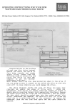
1
12843 Foothill Blvd.
Suite D
Sylmar, CA 91342
818 898 3380 voice
818 898 3360 fax
www.dnfcontrols.com
GTP - 32
GPI TALLY PROCESSOR
Formerly Tally Interface Box
Setup Manual
TABLE OF CONTENTS
I.
REVISION HISTORY ............................................................................. 2
II.
GETTING STARTED ............................................................................... 3
III.
USING THE GPI TALLY PROCESSOR...................................................... 3
IV.
GPI TALLY PROCESSOR OVERVIEW...................................................... 3
V.
COMBINATORIAL LOGIC OPTION OVERVIEW....................................... 5
VI.
EVENT LOGGING OPTION OVERVIEW................................................... 6
VII.
SETUP .................................................................................................. 7
VIII.
EVENT MONITORING.......................................................................... 20
IX.
SOURCE EVENT DEFINITION .............................................................. 34
X.
COMBINATORIAL EVENT DEFINITION (Optional) .............................. 34
XI.
EVENT LOGGING (OPTIONAL) ............................................................ 42
XII.
FRONT & REAR VIEWS ....................................................................... 43
XIII.
LIMITED WARRANTY.......................................................................... 44
GPI Tally Processor, Setup Manual
Page 1 of 44
I.
REVISION HISTORY
011305 Rev. 1.0
Original Document
093005 Rev. 1.1
Revised to conform to current software. V1.87
120905 Rev. 1.2
Separated into setup and installation manual.
012406 Rev. 1.3
Inserted event logging instructions.
Page 2 of 44
GPI Tally Processor, Setup Manual
II. GETTING STARTED
Configure the GPIs and GPOs per instructions in the SETUP section. This step is
required after initial installation and after changing external GPIs or GPOs.
This step will accomplish the following:
A. Configure the GPI TALLY PROCESSOR software specifically for the GPIs and
GPOs it will be connected to.
B. Set user selected password.
C. Set the system label to uniquely identify the GPI TALLY PROCESSOR.
III. USING THE GPI TALLY PROCESSOR
Build an Event Monitor Table to route GPIs to GPOs following instructions in the
EVENT MONITOR TABLE section. This step is required when GPI or GPO routing
must be created or changed.
This step will accomplish the following:
A. Assign control of a GPO to one or more GPIs.
B. Assign control of a GPO to a Remote Source Event Definition or Combinatorial
Event Definition.
C. Save the Event Monitor Table in a file for later restore.
D. Build more than one Event Monitor Table for later restore.
IV. GPI TALLY PROCESSOR OVERVIEW
The GPI TALLY PROCESSOR is a GPI/Tally router, GPI/Tally distributor, and a
GPI/Tally combiner. As a GPI/Tally router, any GPI may be routed to any GPO.
GPIs may be located on the GPI TALLY PROCESSOR or located on another,
remote GPI TALLY PROCESSOR. When the GPI turns ON, the associated GPO is
turned ON. When the GPI turns OFF, the GPO is turned OFF.
As a GPI/Tally distributor, one GPI can be routed to many GPOs. GPOs may be
located on the GPI TALLY PROCESSOR or located on another, remote GPI TALLY
PROCESSOR. When the GPI turns ON, all of the associated GPOs will turn on.
When the GPI turns OFF, all of the GPOs will turn off.
As a GPI/Tally combiner, many GPIs can be routed to one GPO. GPIs may be
located on the GPI TALLY PROCESSOR or located on another, remote GPI TALLY
PROCESSOR. In this situation, when at least one of the GPIs turns on, the
GPI Tally Processor, Setup Manual
Page 3 of 44
associated GPO is turned ON. Only after all of the these GPIs turn off, the GPO is
turned off.
The GPI TALLY PROCESSOR is comprised of 3 major sections:
GPI Section
(opto-isolated
Inputs)
Event Processing
Logic Section
GPO Section
(Relay contact
isolated outputs)
GPI Section
The GPI Section is responsible for providing isolation between the various GPI
sources and the GPO devices, as well as detecting active GPIs. Each GPI input is
isolated using an opto-isolator that requires a differential voltage across it to turn
it on. This input supports positive and negative voltages, active high GPI
sources, and active low GPI sources. The GPI source must provide the
differential voltage required to turn on the opto-isolator. No voltage or current is
supplied by the GPI TALLY PROCESSOR to power the opto-isolators
Event Processing Logic Section
The Event Processing Section is the Event Monitoring Table. The Event
Monitoring Table is the power of the GPI TALLY PROCESSOR, routing GPI Inputs
to GPO Outputs. The state of each GPO is dependent upon the state of the GPI it
is routed to. The GPI state is dependent upon the external device it is connected
to.
The GPI TALLY PROCESSOR monitors local and remote GPIs to control the state
of the “Local GPOs”, GPOs that are located inside the GPI TALLY PROCESSOR.
“Local GPIs” are GPIs that are located inside the GPI TALLY PROCESSOR.
“Remote GPIs” are GPIs located in another GPI TALLY PROCESSOR that is
connected via ethernet, intranet, or internet to this GPI TALLY PROCESSOR.
The GPI TALLY PROCESSOR monitors the current state of a GPI. When the GPI
turns “ON”, the associated GPO is affected by the assigned “ON FUNCTION”,
typically “Turn On GPO”. When the GPI turns “OFF”, the associated GPO is
affected by the assigned “OFF FUNCTION”, typically “Turn Off GPO”.
In the Event Monitoring Table, a single GPI may be routed to control a single
GPO. A single GPI may be routed to control many GPOs. Also, many GPIs may
be routed to control a single GPO.
The Event Monitoring Table uses combining logic to support the “One to Many”
and “Many to One” relationships. If three (3) GPIs (i.e.: production switcher tally
outputs) are routed to control the same GPO, (i.e.: camera tally light), the
camera tally light will turn on if ANY one of the three GPIs is turned on. The
camera tally light will only turn off when ALL three GPIs are turned off.
Page 4 of 44
GPI Tally Processor, Setup Manual
Each row in the Event Monitoring Table is used to route one GPI to one GPO. To
use one GPI to control many GPOs, add a row for each GPO to be controlled. To
use many GPIs to control one GPO, add one row for each GPI.
GPO Section
The GPO section is made up of relay contact closures, providing isolation between
the GPI sources and the various GPO controlled devices. Each GPO output is a
normally open, relay contact pair. The GPO output is a “dry” contact closure. No
voltage or current is provided by the GPI TALLY PROCESSOR.
V.
COMBINATORIAL LOGIC OPTION OVERVIEW
The Combinatorial Logic Option for the GPI TALLY PROCESSOR delivers Tally
Intelligence. In addition to one tally input controlling one tally output, the
Combinatorial Logic Option allows one tally output to be controlled by multiple
tally inputs based upon a user-entered definition. Now, diode OR’ing and other
“glue logic” circuits are no longer necessary.
The Combinatorial Event Definition screen, available through the GPI TALLY
PROCESSOR’s web interface is used by the operator to create a combinatorial
event definition.
The combinatorial event definition consists of:
A. Unique user entered name (event identifier)
B. User entered equation that contains a list of GPI sources to monitor and
logical operators (AND, OR, NOT, XOR, NAND, and NOR).
C. User selected “Available: Yes” or “Available: No” allows the definition to be
temporarily disabled.
Combinatorial Event Definitions may be added, deleted, or modified at any time
without affecting system operation or requiring a system reboot. Combinatorial
Event Definitions may also be nested in other Combinatorial Event Definitions.
After defining Combinatorial Event Definitions, their event identifiers may be used
in the Channel Event Monitoring Table as a source to affect local GPOs. Remote
GPI TALLY PROCESSORs may also use these event identifiers in their Channel
Event Monitoring Tables to affect GPOs.
The individual components of the Combinatorial Event Definition are monitored
on a real-time basis by the Event Monitoring Table. When the current states of
the components cause the definition to become true, the GPO assigned in the
Event Monitoring Table will be controlled by the associated “ON Function”. When
GPI Tally Processor, Setup Manual
Page 5 of 44
the current states of the components cause the definition to become false, the
assigned GPO will be controlled by the associated “OFF Function”.
VI. EVENT LOGGING OPTION OVERVIEW
The EVENT LOGGING option allows the GTP to log each GPI and GPO change
(also referred to as “event”) into a log file on the GTP. For each GPI/GPO event,
the GPI/GPO number, current state (ON or OFF) along with the system date and
time will be saved into the log file. If the LTC time code option is installed, the
“House System Time” will also be saved.
The EVENT LOGGING option will maintain 7 log files, one log file for each day of
the week. At midnight, based upon the GTP’s internal clock, the logging will
continue in the next day’s file. On the 8th day, the oldest log file will be deleted
and replaced with a new empty file.
Each daily log file is actually two separate files, elog-xxx-0.txt and elog-xxx1.txt. The “-0.txt” file is used first and when full, the “-1.txt” file is used. The
two files will hold a maximum of approximately 40,000 events. If the number of
logged events for a day exceeds this maximum number, the “-0.txt” file will be
overwritten with the new events.
The data in the log file will be in a standard comma delimited format, (CSV,
Comma-Separated-Value). This file can be uploaded to a “PC” and viewed with
any text editing program or word processor. It can also be imported into a
spreadsheet or database program for viewing or statistical analysis. There is no
user intervention necessary to start the logging feature, it is always active.
Page 6 of 44
GPI Tally Processor, Setup Manual
VII.SETUP
Setup is required after initial installation. Setup may also be required after
changing external GPIs or GPOs.
Setup is performed using a computer running an off the shelf web browser such
as “Microsoft Internet Explorer” or “Netscape”. Connect the CAT5 cable from the
computer to the same ethernet hub that the GPI TALLY PROCESSOR is connected
to.
After launching the web browser, enter the IP address of the GPI TALLY
PROCESSOR to be setup. The GPI TALLY PROCESSOR Home Page will be
displayed.
A. Set Password
The default password, when shipped from the factory, is “controls”, all lower
case. The password is used to access all configuration screens.
GPI Tally Processor, Setup Manual
Page 7 of 44
Using the web browser:
1. From the Tally Interface Home Page, click on the “System” link. The
System page will be displayed.
2. Click on “Set Password”. The Set Password page will be displayed.
Page 8 of 44
GPI Tally Processor, Setup Manual
3. In the “Old password” entry box, enter the current password.
Note: When shipped from the factory, the default password is
“controls”, all lower case.
4. Enter the new password in the “New Password” entry box.
5. Enter the new password in the “Verify New Password” entry box.
6. Click on “Save” to save the new password.
OR
Click on “Cancel” to exit without changing passwords.
Note: If the “New Password” entry and the “Verify New Password”
entry do not match, an error will be displayed.
GPI Tally Processor, Setup Manual
Page 9 of 44
B. Set System Label
The System Label is used to uniquely identify a GPI TALLY PROCESSOR. This
name is associated with the IP address.
Using the web browser:
1. From the Tally Interface Home Page, click on the “System” link. The
System page will be displayed.
2. Click on “Set System Label”. The Set System Label page will be
displayed.
Page 10 of 44
GPI Tally Processor, Setup Manual
3. Enter any name made up of letters, numbers, or special characters, up
to 16 characters.
4. Click on “Save” to save the name entered in step 3).
OR
Click on “Cancel” to exiting without changing the System Label.
GPI Tally Processor, Setup Manual
Page 11 of 44
C. Set System Time
The system time is only used for error logging. It is not used to process GPIs
or control GPOs.
Using the web browser:
1. From the Tally Interface Home Page, click on the “System” link. The
System page will be displayed.
2. Click on “Set System Time”. The Set System Time page will be
displayed.
3. Using the drop down menus, set the current date and time.
4. Click on “Save” to save the entered date and time.
OR
Click on “Cancel” to exit without saving.
Page 12 of 44
GPI Tally Processor, Setup Manual
D. GPI Setup
Using the web browser:
1. From the GPI TALLY PROCESSOR Home Page, click on the “GPI” link.
The GPI Configuration Table page will be displayed.
2. At the top or bottom of the page, click on the “Edit GPI Configuration
Table” link.
If prompted for password, enter your password then click on “Login” to
log in to the GPI TALLY PROCESSOR. If already logged in, the
password prompt will not be displayed.
GPI Tally Processor, Setup Manual
Page 13 of 44
The GPI Configuration Table will be displayed with drop down boxes.
Page 14 of 44
GPI Tally Processor, Setup Manual
3. For each GPI, do the following:
Note: It is only necessary to change these settings to achieve specific
functions. Under normal use these will remain at their default
settings.
a) Enter a label name to help identify the GPI with a source
function.
b) Set the “User Define ON State”. Click on the drop down arrow.
Select OPTO ON if the GPI is considered “ON” when power
(+V or –V) is applied across the GPI TALLY PROCESSOR’s
opto-isolator 2-wire input.
Select OPTO OFF if the GPI is considered on when no power
is applied across the GPI TALLY PROCESSOR’s opto-isolator
2-wire input.
c) Set the “User Defined ON Mode”. Click on the drop down arrow.
Select LATCHED if the GPI source signal turns on and stays on
when activated. The GPI source signal turns off and stays off
when de-activated (GPI follows the source signal). This is the
recommended setting.
Select MOMENTARY if the GPI source signal turns on for a
specific duration then automatically turns off, when activated.
d) If MOMENTARY is selected in step c) above, enter a “Debounce”
time in the DEBOUNCE box. If LATCH was selected, debounce
time is ignored.
The debounce time is used to filter out unwanted GPI signals.
If the debounce time is greater than that GPI’s on time, then
the GPI will be ignored. If the debounce time is less that the
GPI on time, then the GPI will be detected.
Set the debounce time to the minimum on time of the GPI to be
detected.
All debounce time entries are automatically multiplied by
10milliseconds. The minimum entry is “1”, for 10 milliseconds.
The maximum entry is “255” for 2550 milliseconds. All entries
greater than “255” will be set to “255”.
GPI Tally Processor, Setup Manual
Page 15 of 44
Examples:
For a debounce time of 30 milliseconds, enter “3”. For a debounce
time of 65 milliseconds, enter “6” or “7”, for 60 or 70 milliseconds,
respectively.
4. After entering GPI configuration data, click on SAVE to save the
entered configuration data or click on CANCEL to exit without saving.
Page 16 of 44
GPI Tally Processor, Setup Manual
E. GPO Setup
Using the web browser:
1. From the GPI TALLY PROCESSOR Home Page, click on the “GPO” link.
The GPO Configuration Table page will be displayed.
2. At the top or bottom of the page, click on the “Edit GPO….
Configuration Table” link.
If prompted for password, enter your password then click on “Login” to
log in to the GPI TALLY PROCESSOR. If already logged in, the
password prompt will not be displayed.
GPI Tally Processor, Setup Manual
Page 17 of 44
The GPO Configuration Table will be displayed with drop down boxes.
Page 18 of 44
GPI Tally Processor, Setup Manual
3. For each GPO, do the following:
Note: It is only necessary to change these settings to achieve specific
functions. Under normal use these will remain at their default settings.
a) Enter a label name to help identify the GPO with an output
function.
b) Set the “User Defined ON State”. Click on the drop down arrow.
Select “RELAY CLOSED” if the GPO is considered “ON” when the
relay contacts are closed. In this mode the relay will pass a
signal or ground from the COM contact to the NORMALLY OPEN
contact.
Select “RELAY OPEN” if the GPO is considered “ON” when the
relay contacts are open. In this mode the relay will NOT pass
any signal voltage or ground from the COM contact to the
NORMALLY OPEN contact.
c) Set the “User Defined ON Mode”.
Select LATCHED if the GPO should stay ON or OFF until told to
change states(GPO follows the assigned GPI). This is the
recommended setting.
Select MOMENTARY if the GPO should turn ON for a finite period
of time then automatically turn OFF without being told to turn
OFF.
d) If MOMENTARY is selected in step c) above, enter an ON TIME.
The GPO will turn on for the ON TIME, then automatically turn
OFF.
All ON TIME entries are automatically multiplied by
10milliseconds. The minimum entry is “1”, for 10 milliseconds.
The maximum entry is “255” for 2550 milliseconds. All entries
greater than “255” will be set to “255”.
Examples:
For an on time of 30 milliseconds, enter “3”. For an on time of
65 milliseconds, enter “6” or “7”, for 60 or 70 milliseconds,
respectively.
GPI Tally Processor, Setup Manual
Page 19 of 44
4. After entering GPO configuration data, click on SAVE to save the
entered configuration data or click on CANCEL to exit without saving.
F. Additional Setups
No additional setups are required in “Event Diagnostic” or “System
Maintenance” for normal operation. The LOGOUT link is used to log out of
the GPI TALLY PROCESSOR thereby disallowing any changes that are
password protected.
VIII.
EVENT MONITORING
The Event Monitor Table, the power of the GPI TALLY PROCESSOR, routes GPI
Inputs to GPO Outputs. The state of each GPO is dependent upon the state of
the GPI that it is routed to. The GPI state is determined by the external device
that it is connected to.
The GPI TALLY PROCESSOR monitors local and remote GPIs to control the state
of the “Local GPOs”, GPOs that are located inside the GPI TALLY PROCESSOR.
“Local GPIs” are GPIs that are located inside the GPI TALLY PROCESSOR.
“Remote GPIs” are GPIs located in another GPI TALLY PROCESSOR, on the same
local area network.
The GPI TALLY PROCESSOR monitors the current state of a GPI. When the GPI
turns “ON”, the associated GPO is affected by the assigned “ON FUNCTION”,
typically “Turn On GPO”. When the GPI turns “OFF”, the associated GPO is
affected by the assigned “OFF FUNCTION”, typically “Turn Off GPO”.
In the Event Monitoring Table, a single GPI may be routed to control a single
GPO. A single GPI may be routed to control many GPOs. Also, many GPIs may
be routed to control a single GPO.
The Event Monitoring Table uses combining logic to support the “One to Many”
and “Many to One” relationships. If three (3) GPIs (i.e.: production switcher
tally outputs) are routed to control the same GPO, (i.e.: camera tally light), the
camera tally light will turn on if ANY one of the three GPIs is turned on. The
camera tally light will only turn off when ALL three GPIs are turned off.
Each row in the Event Monitoring Table is used to route one GPI to one GPO. To
use one GPI to control many GPOs, add a row for each GPO to be controlled. To
use many GPIs to control one GPO, add one row for each GPI.
Page 20 of 44
GPI Tally Processor, Setup Manual
A. Launch Web Browser
1. Launch the web browser on the computer connected through an
ethernet hub to the GPI TALLY PROCESSOR. Most off the shelf web
browsers, like Microsoft Internet Explorer or Netscape, may be used.
2. Enter the IP address of the GPI TALLY PROCESSOR to be setup. The
GPI TALLY PROCESSOR Home Page will be displayed.
3. Click on the “Event Monitoring” link. The Event Monitor Table page will
be displayed.
GPI Tally Processor, Setup Manual
Page 21 of 44
B. ADD a row to the Event Monitor Table
Using the web browser:
1. Click on the “Event Monitoring” link at the top of the page. The Event
Monitor Table will be displayed.
2. Click on “Add … Channel Event”. The entry screen will be displayed.
3. Select Status “Enabled” from the drop down menu.
4. Select Source event type, “Local” or “Remote”.
5. Enter the Source IP address, Enter 0.0.0.0 to monitor a local event or
the IP address of the Remote GPI TALLY PROCESSOR to monitor.
Page 22 of 44
GPI Tally Processor, Setup Manual
6. Select a Source Event Label. This is the source that will be monitored.
For example, to monitor a GPI, enter “GPI_1”.
7. Select “Repetitive” from the FREQUENCY drop down menu.
8. Select the Destination GPO number from the drop down menu. This is
the GPO that will be controlled by the GPI or event entered in step 5)
above.
9. Select the “ON FUNCTION”. This is the function that will execute each
time the GPI turns on. From the drop down menu select “Turn On
GPO”.
10. Select the “OFF FUNCTION”. This is the function that will execute each
time the GPI turns off. From the drop down menu select “Turn Off
GPO”. If the GPO is controlled by more than one GPI, all GPIs must
turn off before the OFF FUNCTION will execute.
11. Click on SAVE and EXIT to save the entry and exit to the previous
page.
Click on SAVE and Add to save the entry and continue to add events.
OR
Click on DONE to exit without saving.
Note: Duplicate events are not permitted in the table. If an added
row is a duplicate of an existing row, the new row will not be added to
the table.
GPI Tally Processor, Setup Manual
Page 23 of 44
C. EDIT a row in the Event Monitor Table
Using the web browser:
1. Click on the “Event Monitoring” link at the top of the page. The Event
Monitor Table will be displayed.
2. Click on “Edit … Channel Event”. The row selection page will be
displayed.
3. Click the “All” box to edit all rows OR click on the desired row(s) to
edit.
4. Click on “EDIT” at the bottom of the table.
OR
Click on “BACK” to return to the previous page.
Page 24 of 44
GPI Tally Processor, Setup Manual
5. On the next screen the selected events, in consecutive order, will show
their current contents with drop down menus to permit editing.
6. Modify the contents of the items in the event.
7. Click on SAVE to save the entry.
Click on NEXT to edit the next selected event.
OR
Click on DONE to exit without saving.
Note: Duplicate events are not permitted in the table. If an edited
row is a duplicate of an existing row, the edited row will be restored
with its original data.
GPI Tally Processor, Setup Manual
Page 25 of 44
D. DELETE a row in the Event Monitor Table
Using the web browser:
1. Click on the “Event Monitoring” link at the top of the page. The Event
Monitor Table will be displayed.
2. Click on “Delete … Channel Event”. The row selection page will be
displayed.
3. Click the “All” box to delete all rows
OR
Click the desired row(s) to delete.
Page 26 of 44
GPI Tally Processor, Setup Manual
4. Click on “DELETE” at the bottom of the table. The “Are You Sure” page
will be displayed. OR, click on “CANCEL” to return to the previous
page.
5. Click on “DELETE” at the bottom of the page to delete the selected
rows.
OR
Click on “CANCEL” to return to the previous page without deleting.
GPI Tally Processor, Setup Manual
Page 27 of 44
E. Save Event Monitor Table File
Save the current Event Monitor Table as a file in the GPI TALLY PROCESSOR’s
non-volatile memory for later recall.
Multiple Event Monitor Table files may be created then saved for later recall.
This provides a quick and easy way to change GPI/GPO routing during an
event.
Using the web browser:
1. Click on the “Event Monitoring” link at the top of the page. The Event
Monitor Table will be displayed.
2. Click on “Backup….Channel Events”. The “Save Event Monitor Table”
page will be displayed.
The list of currently saved Event Monitor Table files is displayed. If no
Event Monitor Table files have been saved, "No files found" will be
displayed.
3. Enter a unique 8 character name in the “Enter File Name” field.
4. Click on “SAVE” to save the Event Monitor Table in a file of the entered
name.
OR
Click “DONE” to return to the previous page without saving.
Page 28 of 44
GPI Tally Processor, Setup Manual
F. Download Event Monitor Table File to Computer
Download the Event Monitor Table file to the computer.
Multiple Event Monitor Table files may be created then saved for later recall.
This provides a quick and easy way to change GPI/GPO routing during an
event.
Using the web browser:
1. Click on the “Event Monitoring” link at the top of the page. The Event
Monitor Table will be displayed.
2. Click on “Backup…..Channel Events”. The “Save Event Monitor Table”
page will be displayed.
3. From the list of displayed “Saved Event Monitor Table Files”, select a
file. If no Event Monitor Table files have been saved, "No files found"
will be displayed. The Download process cannot continue.
4. After selecting a file, press the right mouse button. If the mouse if
configured for “Left-handed” operation, press the left mouse button.
The web browser will prompt to “Save the Link as” or “Save Target
as”. Follow the web browser’s prompts to copy the file to the
computer.
GPI Tally Processor, Setup Manual
Page 29 of 44
G. Restore Event Monitor Table File
Restore a saved Event Monitor Table file as the current Event Monitor Table.
Also, upload an Event Monitor Table file from a computer to the GPI TALLY
PROCESSOR.
Using the web browser:
1. Click on the “Event Monitoring” link at the top of the page. The Event
Monitor Table will be displayed.
2. Click on “Restore …..Channel Event”. The “Restore Event Monitor
Table” page will be displayed.
3. From the list of displayed “Saved Event Monitor Table Files”, select a
file. If no Event Monitor Table files have been saved, "No files found"
will be displayed. The Restore process cannot continue.
4. After selecting a file, click on “RESTORE” to restore this file as the
current Event Monitor Table.
OR
Click “CANCEL” to return to the previous page without restoring.
Page 30 of 44
GPI Tally Processor, Setup Manual
H. Upload Event Monitor Table File from Computer
Upload an Event Monitor Table file saved on a computer to the GPI TALLY
PROCESSOR.
Using the web browser:
1. Click on the “Event Monitoring” link at the top of the page. The Event
Monitor Table will be displayed.
2. Click on “Restore …..Channel Event”. The “Restore Event Monitor
Table” page will be displayed.
3. Click on “BROWSE” to browse the list of files on the computer.
4. Select the file to be transferred to the GPI TALLY PROCESSOR.
5. Click on “Upload to GPI TALLY PROCESSOR”. The selected file will be
transferred to the GPI TALLY PROCESSOR’s non-volatile memory.
GPI Tally Processor, Setup Manual
Page 31 of 44
I. Delete Event Monitor Table File from GPI TALLY
PROCESSOR
Using the web browser:
1. Click on the “Event Monitoring” link at the top of the page. The Event
Monitor Table will be displayed.
2. Click on “Restore ….Channel Event”. The “Restore Event Monitor
Table” page will be displayed.
3. From the list of displayed “Saved Event Monitor Table Files”, select a
file. If no Event Monitor Table files have been saved, "No files found"
will be displayed. The Delete process cannot continue.
Page 32 of 44
GPI Tally Processor, Setup Manual
4. After selecting a file, click on “Delete Saved File” to delete the selected
file. The following page will be displayed:
5. Click “Delete” to delete the selected file.
OR
Click “Cancel” to cancel the delete process.
GPI Tally Processor, Setup Manual
Page 33 of 44
IX. SOURCE EVENT DEFINITION
Source Event Definition is used to define remote source events occuring on
another GTP that may be monitored by the local Event Monitor Table.
Note: Source Event definitions are not required to add local or remote GPIs to
the Event Monitor Table.
X.COMBINATORIAL EVENT DEFINITION
(Optional)
The Combinatorial Logic Option for the GPI TALLY PROCESSOR delivers Tally
Intelligence. In addition to one tally input (GPI) controlling one tally output
(GPO), the Combinatorial Logic Option allows one tally output to be controlled by
multiple tally inputs based upon a user-entered definition. Now, diode OR’ing
and other “glue logic” circuits are no longer necessary.
The Combinatorial Event Definition screen, available through the GPI TALLY
PROCESSOR’s web interface is used by the operator to create a combinatorial
event definition.
The combinatorial event definition consists of:
A. Unique user entered name (event identifier)
B. User entered equation that contains a list of GPI sources to monitor and
logical operators (AND, OR, NOT, XOR, NAND, and NOR).
C. User selected “Available: Yes” or “Available: No” allows the definition to be
temporarily disabled.
Combinatorial Event Definitions may be added, deleted, or modified at any time
without affecting system operation or requiring a system reboot. Combinatorial
Event Definitions may also be nested in other Combinatorial Event Definitions.
After defining Combinatorial Event Definitions, their event identifiers may be used
in the Channel Event Monitoring Table as a source to affect local GPOs. Remote
GPI TALLY PROCESSORs may also use these event identifiers in their Channel
Event Monitoring Tables to affect GPOs.
The individual components of the Combinatorial Event Definition are monitored
on a real-time basis by the Event Monitoring Table. When the current states of
the components cause the definition to become true, the GPO assigned in the
Event Monitoring Table will be controlled by the associated “ON Function”. When
the current states of the components cause the definition to become false, the
assigned GPO will be controlled by the associated “OFF Function”.
Page 34 of 44
GPI Tally Processor, Setup Manual
1. Combinatorial Event Setup
To view the Combinatorial Event Definition screen, launch a web browser
on the computer connected to the GPI TALLY PROCESSOR through an
ethernet hub. (Most off the shelf web browsers, like Microsoft Internet
Explorer or Netscape, may be used.)
Using the web browserEnter the IP address of the GPI TALLY PROCESSOR. The GPI TALLY
PROCESSOR Home Page will be displayed.
Click on the “Combinatorial Event Definition” link at the top of the page.
The Combinatorial Event Definition Table will be displayed.
GPI Tally Processor, Setup Manual
Page 35 of 44
2. ADD a Combinatorial Event Definition
Using the web browser:
a) Click on the “Combinatorial Event Definition” link at the top of
the page. The Combinatorial Event Definition Table will be
displayed.
b) Click on “Add … Combinatorial Event Definition”. The entry
screen will be displayed.
Page 36 of 44
GPI Tally Processor, Setup Manual
c) In the Event Label box, enter a unique Label of up to 15 alphanumeric characters. This label must be unique on the GPI
TALLY PROCESSOR that it is created on. This unique label will
be used by the local Event Monitor Table and remote Event
Monitor Tables to access this definition.
d) The second box shows the list of “Available Events” that may be
used in the combinatorial event definition. Manually enter an
source event followed by a logic operator followed by another
source event.
e) Select “YES” in the “Available” column to allow this definition to
be used. Select “NO” to temporarily disable this definition.
f) Click on “Save and Exit” to save the entered combinatorial
event definition and Exit.
OR
Click on “Save and Add” to continue to enter additional events.
OR
Click on “Cancel” to exit without saving.
Note: “Available” for the event definition will be set to
Disabled if an source event entered in step 4 above does not
exist or has been misspelled. To correct, select edit to re-enter
the source event name(s).
The individual components of the entered combinatorial
definition are monitored on a real-time basis by the Event
Monitor Table. When the current states of the components
cause the definition to become true, the GPO assigned in the
Event Monitoring Table will be controlled by the “ON Function”.
When the current states of the components cause the definition
to become false, the assigned GPO will be controlled by the
“OFF Function”.
GPI Tally Processor, Setup Manual
Page 37 of 44
3. EDIT a Combinatorial Event Definition
Using the web browser:
a) Click on the “Combinatorial Event Definition” link at the top of
the page. The Combinatorial Event Definition Table will be
displayed.
b) Click on “Edit … Combinatorial Event Definition”. The selection
screen will be displayed.
c) Click the “All” box to edit all combinatorial event definitions OR
click on the desired event definition to edit.
d) Click on “Edit” to edit the selected items.
OR
Click on “Back” to return to the previous screen.
Page 38 of 44
GPI Tally Processor, Setup Manual
The selected items will be displayed.
e) Modify the Label, Value, or Available status of the definition
f) Click on “Save” to save the edited items.
OR
Click on “Back” to return to the previous screen without saving
the changes.
GPI Tally Processor, Setup Manual
Page 39 of 44
4. DELETE a Combinatorial Event Definition
Using the web browser:
a) Click on the “Combinatorial Event Definition” link at the top of
the page. The Combinatorial Event Definition Table will be
displayed.
b) Click on “Delete … Combinatorial Event Definition”. The
definition selection page will be displayed.
c) Click the “Check All” box to delete all definitions OR click the
desired definition(s) to delete.
Page 40 of 44
GPI Tally Processor, Setup Manual
d) Click on “DELETE” at the bottom of the table. The “Are You
Sure” page will be displayed.
OR
Click on “BACK” to return to the previous page.
e) Click on “DELETE” at the bottom of the page to delete the
selected rows.
OR
Click on “BACK” to return to the previous page without deleting.
GPI Tally Processor, Setup Manual
Page 41 of 44
XI. EVENT LOGGING (OPTIONAL)
Overview
The EVENT LOGGING option allows the GTP to log each GPI and GPO change
(also referred to as “event”) into a log file on the GTP. For each GPI/GPO event,
the GPI/GPO number, current state (ON or OFF) along with the system date and
time will be saved into the log file. If the LTC time code option is installed, the
“House System Time” will also be saved.
The EVENT LOGGING option will maintain 7 log files, one log file for each day of
the week. At midnight, based upon the GTP’s internal clock, the logging will
continue in the next day’s file. On the 8th day, the oldest log file will be deleted
and replaced with a new empty file.
Each daily log file is actually two separate files, elog-xxx-0.txt and elog-xxx1.txt. The “-0.txt” file is used first and when full, the “-1.txt” file is used. The
two files will hold a maximum of approximately 40,000 events. If the number of
logged events for a day exceeds this maximum number, the “-0.txt” file will be
overwritten with the new events.
The data in the log file will be in a standard comma delimited format, (CSV,
Comma-Separated-Value). This file can be uploaded to a “PC” and viewed with
any text editing program or word processor. It can also be imported into a
spreadsheet or database program for viewing or statistical analysis. There is no
user intervention necessary to start the logging feature, it is always active.
A. View or Upload Log Files
Using an Internet Browser such as “MS Internet Explorer” or “Netscape
Navigator” you can access the log files. Click on the SYSTEM link on the
GTP’s home page. Click on SYSTEM MAINTENANCE, then click on VIEW
EVENT LOGS. You will see a list of log files. Click on the radio button of the
file you wish to view and then click on the VIEW LOG button to view the log
file on the browser. You can click on the BACK TO FILE LIST button to return
to the list of files or click on any other link to exit the VIEW LOG feature.
To up load a file to a “PC”, while on the EVENT LOG FILE LIST page, right click
on the file which you want to upload, then click on the “Save Target As” item.
This will open a standard “Windows” file dialogue box; here navigate to the
directory where you want to store the file, Click on the SAVE button to
complete the save process.
B. Clear Log Files
To clear the data from a log file, while on the EVENT LOG FILE LIST page,
click on the desired file’s radio button and then click on the CLEAR LOG
button. You will be asked to confirm the clear process, press the CONFIRM
button to complete the process or press CANCEL to exit without clearing the
file.
Page 42 of 44
GPI Tally Processor, Setup Manual
XII.FRONT & REAR VIEWS
Front View
Rear View
GPI Tally Processor, Setup Manual
Page 43 of 44
XIII.
LIMITED WARRANTY
DNF Controls warrants its product to be free from defects in material and
workmanship for a period of one (1) year from the date of sale to the original
purchaser from DNF Controls.
In order to enforce the rights under this warranty, the customer must first
contact DNFs Customer Support Department to afford the opportunity of
identifying and fixing the problem without sending the unit in for repair. If DNF’s
Customer Support Department cannot fix the problem, the customer will be
issued a Returned Merchandise Authorization number (RMA). The customer will
then ship the defective product prepaid to DNF Controls with the RMA number
clearly indicated on the customer’s shipping document. The merchandise is to be
shipped to:
DNF Controls
12843 Foothill Blvd., Suite D
Sylmar, CA 91342
USA
Failure to obtain a proper RMA number prior to returning the product may result
in the return not being accepted, or in a charge for the required repair.
DNF Controls, at its option, will repair or replace the defective unit. DNF Controls
will return the unit prepaid to the customer. The method of shipment is at the
discretion of DNF Controls, principally UPS Ground for shipments within the
United States of America. Shipments to international customers will be sent via
air. Should a customer require the product to be returned in a more expeditious
manner, the return shipment will be billed to their freight account.
This warranty will be considered null and void if accident, misuse, abuse,
improper line voltage, fire, water, lightning or other acts of God damaged the
product. All repair parts are to be supplied by DNF Controls, either directly or
through its authorized dealer network. Similarly, any repair work not performed
by either DNF Controls or its authorized dealer may void the warranty.
After the warranty period has expired, DNF Controls offers repair services at
prices listed in the DNF Controls Price List. DNF Controls reserves the right to
refuse repair of any unit outside the warranty period that is deemed nonrepairable.
DNF Controls shall not be liable for direct, indirect, incidental, consequential or
other types of damage resulting from the use of the product.
###
Page 44 of 44
GPI Tally Processor, Setup Manual