1
Pepper Controller | User Manual.
Ataraxia Pepper Controller | User Manual.
peace of mind
Operating across a vast range of industries, we use our expertise and insights to respond to client needs in
sustainable and innovative ways. As such we bring our philosophy of sustainable solutions through partnership to
life by remaining committed to finding new and innovative ways to address the challenges of today and tomorrow.
At Ataraxia we consistently strive to exceed your expectations, delivering technology with advanced cutting edge
solutions no matter the scale or scope of your PROBLEM. We pride ourselves on our ability to provide and deliver
the highest level of support.
The Ultimate goal – ‘Peace of Mind’
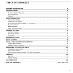
System Overview
Software
About
Installing the software
Monitoring
Using the software
Features
General Operation
Remotes
Arming the System
Disarming The System
Intrusion alarm
Unit Description
Terminals
Wiring the unit
Add-on Modules
GSM Cell Module
MODBUS Unit
Appendix
Modbus Registers Used
Index
Warrante
LED indicators
Ataraxia Pepper Controller | User Manual.
peace of mind
System Overview
About the Ataraxia Pepper Spray Unit
Thank you for purchasing the Ataraxia Pepper spray alarm system. You have made a wise decision in choosing it, for It uses the
latest in microcontroller technology and is specifically designed as a pepper spray alarm controller and SMS notification system.
The pepper spray alarm controller has been designed to provide the easiest configuration and the best possible convenience to the
user for setting up the controller. Please read this manual carefully before attempting to interface to the controller.
Monitoring
This system is capable of transmitting alarms, troubles and emergency information over GSM networks
via SMS messages to specified users. If you inadvertently initiate an alarm, immediately notify the central station to prevent an
unnecessary response.
NOTE: The SMS notification function must be enabled by the installer before it becomes functional.
Features:
•
•
•
•
•
•
•
•
Canister Level Monitoring (Resettable with pushbutton)
Support for External Status LED’s
External Alarm Output Relay (Closed contact on Alarm)
Supports control for 2 Pepper Canisters (Individual Zones)
128 bit Encrypted Remotes with Unique User Id for Armed and Disarmed State
Adjustable Siren Time
Adjustable pepper spray release time and dwell time
SMS Notifications on selectable alarm/fault states.
General System Operation
Your Pepper spray alarm system is made up of a QDE-ATX-MP1 Controller, one or more PIR’s, a 7Amp/hr 13.5 Volt Battery, 12Volt
Actuator, Siren, 16Vac 1.25 A power transformer and a Ataraxia pepper gas canister. One or more remotes is supplied with the
system that is specifically code locked to the Ataraxia Units. the main controller have an audible indicator for specific events and
LED’s to indicate specific statuses.
IMPORTANT NOTICE
Security systems are generally very reliable but they may not work under all conditions and they are not a substitute for prudent
security practices or life and property insurance. Your security system should be installed and serviced by qualified security
professionals who should instruct you on the level of protection that has been provided and on system operations.
Ataraxia Pepper Controller | User Manual.
peace of mind
Remotes
Remotes are used to arm and disarm the system. Up to 15 Remotes can be programmed into each controlled via the supplied
configuration software. A username can be tagged to each remote for customised SMS messages when a system is armed or
disarmed. Please note that a system cannot be armed whilst the sensors detect movement. When a user tries to arm a unit while
the sensor(s) detects movement, the internal buzzer will beep three times.
Arming the system
When the remote is pressed and siren sounds once, the system is armed. If the external status LED is used, it will light up to indicate
that the system is armed. Please do not enter the site after the system is armed as it will result in the pepper gas being released,
and SMS notifications to be sent to all configured users
Disarming the system
When the remote is pressed and siren sounds twice, the system is disarmed. If the external status LED is used, the light will go out
to indicate that the system is disarmed. You can now enter the site as the Pepper gas release system is disabled. If configured, the
controlled will send SMS’s to users indicating that the system was disarmed.
Intrusion Alarm
If an intrusion alarm sounds, indicated by a continuous bell or siren (configurable time period), the alarm may be silenced by pressing
the remote supplied with the unit. This will disarm the unit. Please note that the pepper gas would have been released in the site and
caution must be taken before entering the site.
NOTE: If you return and find that an alarm has occurred while you were away, it is possible thatan intruder
may still be on the premises.
Ataraxia Pepper Controller | User Manual.
peace of mind
Unit Wiring
Terminals:
Please see below the names of the terminals as well as the meaning of each terminal and the use for it.
Power Supply
If you are powering from an AC Transformer (16 - 24Vac 1.5A Min) use the two terminals marked AC on the far right hand side of
the unit.
CAUTION: The battery terminals may not be reversed or wired improperly. Doing this will cause irreversible damage
to the controlled as well as the connected sensors.
Ataraxia Pepper Controller | User Manual.
peace of mind
Powering from Solar Panel
If you are powering the unit from a solar panel use the two terminals marked AC/SOL on the far right hand side of the unit. Positive
and negative wires from the solar panel do not need to be in specific terminal order.
Caution: The battery terminals may not be reversed or wired improperly. Doing this will cause irreversible damage to
the controller as well as the connected sensors.
Connecting the Battery
Connect the Positive side of the battery to the Red battery lead or directly to the terminal marked: BAT / POS. Connect the Negative
side of the battery to the black battery lead or directly to the terminal marked: BAT / POS
Caution: The battery terminals may not be reversed or wired improperly. Doing this will cause irreversible
damage to the controller as well as the connected sensors.
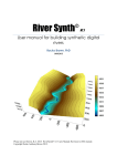
Connecting the PIR or other sensors.
For each of the two zones on the controller, there are two connections for connecting sensors. For Zone 1, they are named Z01/P1A
and Zo1/P1B. For Zone 2, it is named Z02/P1A and Zo2/P1B. The 12V terminal and Gnd terminal next to the zone input terminals, is to
provide power to the sensors which may require power.
(i.e. PIR sensors). The zone input is active when the P1A and/or P1B terminal is not linked to ground. (Normally closed). PIA and PIB
can be disabled\ enabled via the configuration software. The image below shows how the sensors should be connected.
Ataraxia Pepper Controller | User Manual.
peace of mind
Standard Connections of two PIR’s connected to Zone 1 ‘A’ and ‘B’
Using more than one PIR on a Zone input
If you want to connect more than one PIR on a Zone input, do the connection as detailed below.
Please note that the system is wired in a closed loop. If more than one sensor is wired to a single zone input, the sensors MUST be
wired in series configuration.
Ataraxia Pepper Controller | User Manual.
peace of mind
Connecting external LED’s to display the status
You can display the status on external LED’s wired to the outside of a building or structure to display the status of the alarm
controller before you attempt to enter the building. The terminals marked as per the image below, can be used for this purpose. The
EXT 12V power source is a protected power source specifically for the “Arm” and “Safe” LEDs and cannot be used to power any
other device.
Ataraxia Pepper Controller | User Manual.
peace of mind
LED indicators
The main controller has 4 Tri Colour LED’s to display specific statuses and information.
Power LED
When the Power LED is Green, it means that the controller is connected to external power (i.e AC Transformer
or solar panel). When is is red, it means that the External supply is lost or removed. If configured, the “Power
Off” status will send a SMS notification to configured users.
Status LED
The status LED displays the current state of the controller. If Red, it is armed and ready to release gas in the event of
an intrusion. If the light is green, the controlled is disarmed and it is safe to enter the monitored site.
External LED’s can also be wired to show the Status.
Canister LED
When the inserted Pepper Gas canisters is full, the Canister LED will glow bright green. As the gas gets
released, the light will go dimmer. When only 50% volume of the canister is left, the LED will turn yellow
and progress to bright red as the pepper gas volume drops.
Ataraxia Pepper Controller | User Manual.
peace of mind
Software
Installing the Configuration Software
{ToDO}
Using the Configuration Software
Start the Application by clicking on the ‘Ataraxia Configurator’ Icon, located on your desktop or start menu. Click on the ‘Next’ button
to navigate to the ‘Communications TAB’. To communicate with the unit, you need a RS-232 port on your Computer / Laptop. You will
also require the configuration programming cable. Select the port connected to the Main Controller. Click the ‘Read Data From unit’
Button. Follow the progress bar and wait for the ‘Read Complete’ message to appear.
Ataraxia Pepper Controller | User Manual.
peace of mind
Editing Global Settings
Ataraxia Pepper Controller | User Manual.
peace of mind
Editing Remotes
Ataraxia Pepper Controller | User Manual.
peace of mind
Editing Notifiers
Ataraxia Pepper Controller | User Manual.
peace of mind
Downloading the Configuration
Ataraxia Pepper Controller | User Manual.
peace of mind
Add-on Modules
GSM Cell Modem Interface
{ToDo}
RS232 Modbus Interface
Currently the module only supports function-16 Modbus commands (Holding Registers).
These registers, however is all that is required to get all the information from the Ataraxia Controller.
Ataraxia Pepper Controller | User Manual.
peace of mind
Troubleshooting
Viewing Trouble Conditions
The control panel continuously monitors a number of possible trouble conditions. If one of these trouble conditions
occur, it will be displayed on the LED’s or ,if configured, and SMS’s will be sent to specific users.
NOTE: A TROUBLE condition reduces the security your system is designed to provide. Call your installing company for service.
Maintenance
With normal use, the system requires minimum maintenance. The following points should be observed.
1. Do not wash the security station with a wet cloth. Light dusting with a slightly moistened cloth should remove normal
accumulations of dust.
2. The battery/ bell test is designed to determine battery condition. We recommended, however, that the stand-by
batteries be replaced every three years.
3. For other system devices such as smoke detectors, passive infrared, ultrasonic or microwave motion
detectors or glassbreak detectors, consult the respective manufacturer’s literature for testing and maintenance.
Notes to installers
System Failures
This system has been carefully designed to be as effective as possible. There are circumstances, however, involving fire, burglary, or other types
of emergencies where it may not provide protection. Any alarm system of any type may be compromised deliberately or may fail to operate as
expected for a variety of reasons. Some but not all of these reasons may be:
Motion Detectors
Motion detectors can only detect motion within the designated areas as shown in their respective installation instructions. They cannot discriminate
between intruders and intended occupants. Motion detectors do not provide volumetric area protection. They have multiple beams of detection
and motion can only be detected in unobstructed areas covered by these beams. They cannot detect motion which occurs behind walls, ceilings,
floor, closed doors, glass partitions, glass doors or windows. Any type of tampering whether intentional or unintentional such as masking, painting,
or spraying of any material on the lenses, mirrors, windows or any other part of the detection system will impair its proper operation. Passive
infrared motion detectors operate by sensing changes in temperature. However their effectiveness can be reduced when the ambient temperature
rises near or above body temperature or if there are intentional or unintentional sources of heat in or near the detection area. Some of these heat
sources could be heaters, radiators, stoves, barbeques, fireplaces, sunlight, steam vents, lighting and so on.
Access by Intruders
Intruders may enter through an unprotected access point, circumvent a sensing device, evade detection by moving through an area of insuff icient
coverage, disconnect a warning device, or interfere with or prevent the proper operation of the system.
Criminal Knowledge
This system contains security features which were known to be effective at the time of manufacture. It is possible for persons with criminal intent to
develop techniques which reduce the effectiveness of these features. It is important that a security system be reviewed periodically to ensure that
its features remain effective and that it be updated or replaced if it is found that it does not provide the protection expected.
Ataraxia Pepper Controller | User Manual.
peace of mind
Inadequate Installation
A security system must be installed properly in order to provide adequate protection. Every installation should be evaluated by a security professional
to ensure that all access points and areas are covered. Locks and latches on windows and doors must be secure and operate as intended. Windows,
doors, walls, ceilings and other building materials must be of sufficient strength and construction to provide the level of protection expected. A reevaluation must be done during and after any construction activity.
Failure of Replaceable Batteries
This system’s wireless transmitters have been designed to provide several years of battery life under normal conditions. The expected battery life
is a function of the device environment, usage and type. Ambient conditions such as high humidity, high or low temperatures, or large temperature
fluctuations may reduce the expected battery life. While each transmitting device has a low battery monitor which identifies when the batteries
need to be replaced, this monitor may fail to operate as expected. Regular testing and maintenance will keep the system in good operating condition.
Insufficient Time
There may be circumstances when the system will operate as intended, yet the occupants will not be protected from the emergency due to their
inability to respond to the warnings in a timely manner. If the system is monitored, the response may not occur in time to protect the occupants or
their belongings.
Component Failure
Although every effort has been made to make this system as reliable as possible, the system may fail to function as intended due to the failure of
a component.
Inadequate Testing
Most problems that would prevent an alarm system from operating as intended can be found by regular testing and maintenance. The complete
system should be tested weekly and immediately after a break-in, an attempted break-in, a fire, a storm, an earthquake, an accident, or any kind of
construction activity inside or outside the premises. The testing should include all sensing devices, alarm indicating devices and any other operational
devices that are part of the system.
Ataraxia Pepper Controller | User Manual.
peace of mind
Appendix A
Supported Modbus Address Registers
Function
Code
16
16
16
16
16
16
16
16
16
16
16
Address
Description
Min
Max
Unit
0
0
0
0
16bit
0
32bit
120
120
20
30
16bit
30
Sec
Sec
V
V
+1
+2
+3
+4
+5
+6
+7
40 001
40 002
40 003
40 004
40 005
40 006
40 007
Canister Level (Master)
Canister Level (Slave)
Battery Voltage
Supply Voltage
Status Bits (RTU)
SMS Queue Length
Last Armed
+8
+9
+10
+11
40 009
40 011
Last Disarmed
Status Bits (Cell modem)
Ataraxia Pepper Controller | User Manual.
32bit
16bit
16bit
peace of mind
LIMITED WARRANTY
Quantum Design and Engineering (PTY) Ltd. warrants the original purchaser that for a period of twelve months from the date of purchase, the product shall
be free of defects in materials and workmanship under normal use. During the warranty period, Quantum Design and Engineering (PTY) Ltd. shall, at its option,
repair or replace any defective product upon return of the product to its factory, at no charge for labour and materials.
Any replacement and/or repaired parts are warranted for the remainder of the original warranty or ninety (90) days, whichever is longer. The original owner
must promptly notify Quantum Design and Engineering (PTY) Ltd. in writing that there is defect in material or workmanship, such written notice to be received
in all events prior to expiration of the warranty period.
International Warranty
The warranty for international customers is the same as for any customer within South Africa, with the exception
that Quantum Design and Engineering(PTY) Ltd. shall not be responsible for any customs fees, taxes, or VAT that may be due.
Warranty Procedure
To obtain service under this warranty, please return the item(s) in question to the point of purchase. All authorized distributors and dealers have a warranty
program. Anyone returning goods to Quantum Design and Engineering (PTY) Ltd. must first obtain an authorization number. Quantum Design and Engineering
(PTY) Ltd. will not accept any shipment whatsoever for which prior authorization has not been obtained.
Conditions to Void Warranty
This warranty applies only to defects in parts and workmanship relating to normal use. It does not cover:
• damage incurred in shipping or handling;
• damage caused by disaster such as fire, flood, wind, earthquake or lightning;
• damage due to causes beyond the control of Quantum Design and Engineering (PTY) Ltd. such as excessive voltage, mechanical shock or water damage;
• damage caused by unauthorized attachment, alterations, modifications or foreign objects;
• damage caused by peripherals (unless such peripherals were supplied by Quantum Design and Engineering (PTY) Ltd.;
• defects caused by failure to provide a suitable installation environment for the products;
• damage caused by use of the products for purposes other than those for which it was designed;
• damage from improper maintenance;
• damage arising out of any other abuse, mishandling or improper application of the products.
Quantum Design and Engineering (PTY) Ltd’s liability for failure to repair the product under this warranty after a reasonable number of attempts
will be limited to a replacement of the product, as the exclusive remedy for breach of warranty. Under no circumstances shall Quantum Design and Engineering
(PTY) Ltd. be liable for any special, incidental, or consequential damages based upon breach of warranty, breach of contract,
negligence, strict liability, or any other legal theory. Such damages include, but are not limited to, loss of profits, loss of the product or any associated
equipment, cost of capital, cost of substitute or replacement equipment, facilities or services, down time, purchaser’s time, the claims of third parties,
including customers, and injury to property.
Disclaimer of Warranties
This warranty contains the entire warranty and shall be in lieu of any and all other warranties, whether expressed or implied (including
all implied warranties of merchantability or fitness for a particular purpose) And of all other obligations or liabilities on
the part of Quantum Design and Engineering (PTY) Ltd. Quantum Design and Engineering (PTY) Ltd. neither assumes nor authorizes any other person purporting
to act on its behalf to modify or to change this warranty, nor to assume for it any other warranty or liability concerning this product.
Out of Warranty Repairs
Quantum Design and Engineering (PTY) Ltd. will at its option repair or replace out-of-warranty products which are returned to its factory according
to the following conditions. Anyone returning goods to Quantum Design and Engineering (PTY) Ltd. must first obtain an authorization number.
Quantum Design and Engineering (PTY) Ltd. will not accept any shipment whatsoever for which prior authorization has not been obtained.
Products which Quantum Design and Engineering (PTY) Ltd. determines to be repairable will be repaired and returned.
A set fee which Quantum Design and Engineering (PTY) Ltd. has predetermined and which may be revised from time to time, will be charged for each unit
repaired.
Products which Quantum Design and Engineering (PTY) Ltd. determines not to be repairable will be replaced by the nearest equivalent product
available at that time. The current market price of the replacement product will be charged for each replacement unit.
WARNING:
Quantum Design and Engineering (PTY) Ltd. recommends that the entire system be completely tested on a regular basis. However,
despite frequent testing, and due to, but not limited to, criminal tampering or electrical disruption, it is possible for this product to fail to perform as
expected.
Ataraxia Pepper Controller | User Manual.
peace of mind