Transcript
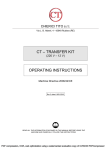
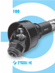
ENGLISH
ENGLISH
INDEX
A
B
C
D
E
F
G
H
I
L
A6
BECOMING ACQUAINTED WITH K24
A1
Measurement System
A2
Display Positioning
A3
Operating modes
A4
LCD display
A5
User Buttons
A6
Battery Housing
INSTALLATION
DAILY USE
C1
Dispensing in Normal mode
C1.1
Partial reset
C1.2
Resetting the Reset Total
C.2
Dispensing with Flow Rate Mode display
C.2.1
Partial reset
CALIBRATION
D1
Definitions
D2
Why Calibrate
D3
Calibration procedure:
D3.1
Display Of Current “K Factor” And Restoring “Factory K Factor”
D3.2
In-field Calibration
D3.2.1
In-field calibration procedure:
D3.3
Direct modification of K factor
METERS CONFIGURATION
MAINTENANCE
MALFUNCTIONS
TECHNICAL SPECIFICATIONS
DISPOSAL
EXPLODED VIEWS AND OVERALL DIMENSIONS
A
Battery Housing
The k24 is powered by two standard type 1.5 V batteries (size AAA).
The battery housing, easily accessible, is closed by a metal cover sealed through a
rubber protection acting as a gasket as well. The whole unit can be easily removed
by unscrewing the 4 screws fixing the cover and the protection to the body.
B
INSTALLATION
K24 features a threaded, perpendicular inlet and outlet (1” gas or ntp male
and female that can be combined together). It has been designed to be easily
installed in any position: fixed in-line or mobile on a dispensing nozzle.
In order to improve the life of the turbine, it is recommended to fit a strainer
before the meter itself
BECOMING ACQUAINTED WITH K24
Electronic digital meter featuring a turbine measurement system, designed for
precise measuring of low viscosity fluids.
It is divided into two using macrogroups:
!
C
ATTENTION
At the female inlets, tighten the couplings at a max. torque of 55N/m.
A1
Measurement System
The only operations that need to be done for daily use are partial and/or resettable
total register resetting.
The user should use only the dispensing system of k24.
Occasionally the meter may need to be configured or calibrated. To do so, please
refer to the relevant chapters.
Below are the two typical normal operation displays.
One display page shows the partial and reset total registers. The other shows the
partial and general total. Switchover from resettable total to general total display
is automatic and tied to phases and times that are in factory set and cannot be
changed.
Turbine measurement system. The turbine is placed inside a hole through the
body of k24, fitted with threaded inlet and outlet. The body of k24 is made of a
plastic material that allows several types of threads with relevant combinations.
K24 has 2 rubber protections, designed to act as gaskets, too, and thus reducing
the number of its components.
The liquids compatible with k24 must be at low viscosity, namely:
- Diesel fuel
- Water
- Water/urea solution
- Kerosene
- Windscreen
- Petrol
Main components:
LCD Display
Reset Button
Cal Button
NOTE: 6 digits are available for Totals, plus two icons x 10 / x100. The
increment sequence is the following:
0.0 → 99999.9 → 999999 → 100000 x 10 → 999999 x 10 → 100000 x 100 →
999999 x 100
C1
Dispensing in Normal mode
Normal mode is the standard dispensing. While the count is made, the partial
and resettable total are displayed at the same time (reset total).
Should one of the keys be accidentally pressed during
dispensing, this will have no effect.
A few seconds after dispensing has ended, on the
lower register, the display switches from resettable
total to general total: the word reset above the word
total disappears, and the reset total is replaced by the
general total.
This situation is called standby and remains stable until
the user operates the k24 again.
C1.1
Partial reset
The partial register can be reset by pressing the reset
key when the meter is in standby, meaning when the
display screen shows the word “TOTAL”.
After pressing the reset key, during reset, the display
screen first of all shows all the lit-up digits and then all
the digits that are not lit up.
At the end of the process, a display page is first of all
shown with the reset partial and the reset total
A2
!
IMPORTANT
Even though in this mode they are not displayed, both the Reset
Total and the General Total (Total) increase. Their value can be
checked after dispensing has terminated, returning to “Normal” mode, by
quickly pressing CAL.
C.2.1
and, after a few moments, the reset total is replaced by
the non resettableTotal.
C1.2
!
A3
Operating modes
The user can choose between two different operating modes:
- Normal Mode: Mode with display of Partial and Total dispensed quantities.
- Flow Rate Mode: Mode with display of Flow Rate, as well as Partial dispensed
quantity.
The meter features a non-volatile memory for storing the dispensing data, even
in the event of a complete power break for long periods.
The measurement electronics and the LCD display are fitted in the top part of
the K24 which remains isolated from the fluid-bath measurement chamber and
sealed from the outside by means of a cover.
A4
LCD display
The “LCD” of the METER features two numerical registers and various indications
displayed to the user only when the applicable function so requires.
Key:
1.
Partial register (5 1
9
figures with moving comma
FROM 0.1 to 99999) indicating
the volume dispensed since the 2
8
reset button was last pressed;
7
2.
Indication of battery 3
charge;
3.
Indication
of
4
5 6
calibration mode;
4.
Totals register (6 figures with moving comma FROM 0.1 to 999999),
that can indicate two types of Total:
4.1.
General Total that cannot be reset (TOTAL)
4.2.
Resettable total (Reset TOTAL)
5.
Indication of total multiplication factor (x10 / x100 )
6.
Indication of type of total, (TOTAL / Reset TOTAL);
7.
Indication of unit of measurement of Totals: L=Litres Gal=Gallons
8.
Indication of Flow Rate mode
9.
Indication of unit of measurement of Partial: Qts=Quarts
Pts=Pints L=Litres
Gal=Gallons
A5
User Buttons
The k24 features two buttons (reset and cal) which individually perform two main
functions and, together, other secondary functions.
The main functions performed are:
-
For the reset key, resetting the partial register and resettable total (reset total)
-
For the cal key, entering instrument calibration mode.
Used together, the two keys permit entering configuration mode, useful for
changing the units of measurements and calibration factor.
NONE
K24 IN STAND BY
2
LONG CAL KEY KEYING
K24 enters calibration mode, shows ”CAL” and displays the
calibration factor in use instead of total. The words “Fact” and
“USER” indicate which of the two factors is currently in use.
3
3 LONG RESET KEY KEYING
K24 shows “CAL” and the partial at zero. K24 is ready to perform
on-site calibration.
4
DISPENSING INTO SAMPLE CONTAINER
Without pressing any KEY, start
dispensing into the sample container.
CALIBRATION
D1
Definitions
Calibration factor or “k factor” :
Multiplication factor applied by the system to the electrical pulses received, to
transform these into measured fluid units.
FACTORY K FACTOR:
Factory-set default factor. It is equal to 1,000. This calibration factor ensures
utmost precision in the following operating conditions:
Fluid diesel fuel
Temperature: 20°c
Flow rate: 10-120 litres/min
Even after any changes have been made by the user, the factory k factor can be
restored by means of a simple procedure.
5
6
USER K FACTOR:
Customized calibration factor, meaning modified by calibration.
D2
Why Calibrate
When operating close to extreme conditions, such as for instance with fluids
close to acceptable range extremes (like diesel fuel at low temperatures) or
in extreme flow rate conditions (close to minimum or maximum acceptable
values), an on-site calibration may be required to suit the real conditions in
which the k24 is required to operate.
D3
Calibration procedure:
7
8
K24 permits making quick and precise electronic calibration by changing the
calibration factor (k factor).
There are 2 different ways of calibration:
1. On-site calibration, performed by means of a dispensing operation.
2. Direct calibration, performed by directly changing the k factor.
To enter the calibration phases it is necessary to press and hold down the
“cal” button.
Why enter the calibration phases?
• Display the currently used calibration factor
• Return to factory k factor after a previous calibration with user k factor
• Change the calibration factor using one of the two previously indicated
procedures.
In calibration mode, the partial and total dispensed quantities indicated on
the display screen take on different meanings according to the calibration
procedure phase. During the calibration, the k24 cannot perform any normal
dispensing operations. In calibration mode, the totals are not increased.
!
WARNING
The k24 features a non-volatile memory.
It keeps the calibration and dispensing data stored even after
replacing new batteries or long periods of inactivity.
9
10
D3.1
Display Of Current “K Factor” And Restoring “Factory K Factor”
Indicated value Real value
SHORT RESET KEY KEYING
K24 is informed that the calibration dispensing operation is
finished.
Make sure dispensing is correctly finished before performing this
operation.
To calibrate the K24, the value indicated by the partial totaliser
(example 9.800) must be forced to the real value marked on the
graduated sample container.
In the bottom left part of the display an arrow appears (upwards
and downwards), THAT SHOWS the direction (increase or
decrease) of the USER K FACTOR value change when the
operations 6 or 7 are performed
SHORT RESET KEY KEYING
Arrow direction changes. The operation can be repeated IF
NECESSARY
Resetting the Reset Total
The reset total resetting operation can only be
performed after resetting the partial register. The reset
total can in fact be reset by pressing the reset key at
length while the display screen shows reset total as on
the following display page:
Schematically, the steps to be taken are:
1. Wait for the display to show normal standby display
page (with total only displayed),
2. Press the reset key quickly
3. The meter starts to reset the partial
4. While the display page showing the reset total is
displayed
Press the reset key again for at least 1 second
5. The display screen again shows all the segments of
the display followed by all the switched-off segments and
finally shows the display page where the reset Reset
Total is shown.
C.2
Dispensing with Flow Rate Mode display
It is possible to dispense fluids, displaying at the same time:
*
the dispensed partial
*
the Flow Rate in [Partial Unit / minute]
as shown on the following display page:
IMPORTANT
The flow rate is measured with reference to the unit of measurement
of the Partial. For this reason, in case of the unit of measurement
of the Partial and Total being different, as in the example shown
below, it should be remembered that the indicated flow rate relates to the
unit of measurement of the partial. In the example shown, the flow rate is
!
( )
100 - E%
100
If the meter indicates less than the real dispensed value (negative error) the new
calibration factor must be higher than the old one as shown in the example. The
opposite applies if the meter shows more than the real dispensed value (positive
error).
ATTENTION
When
the
Factory Factor is
confirmed, the old
User factor is deleted from
the memory
!
In-field Calibration
3
4
5
!
• completely eliminate air from the system before calibrating;
• use a precise Sample Container with a capacity of not less than 5 litres,
featuring an accurate graduated indicator.
• ensure calibration dispensing is done at a constant flow rate equivalent
to that of normal use, until the container is full;
•
not reduce the flow rate to reach the graduated area of the
container during the final dispensing stage (the correct method during
the final stages of sample container filling consists in making short topups at normal operation flow rate) ;
• after dispensing, wait a few minutes to make sure any air bubbles are
eliminated from the sample container; only read the Real value at the end
of this stage, during which the level in the container could drop.
• if necessary, carefully follow the procedure indicated below.
LONG RESET KEY KEYING
K24 shows “CAL” and the partial at zero.
K24 is ready to perform on-site calibration by dispensing.
LONG RESET KEY KEYING
We now go on to Direct change of the calibration factor:
the word “Direct” appears together with the Currently Used
calibration factor. In the bottom left part of the display, an
arrow appears (upwards or downwards) defining the direction
(increase or decrease) of change of the displayed value when
subsequent operations 5 or 6 are performed.
SHORT RESET KEY KEYING
Arrow direction changes. The operation can be repeated to
alternate the direction of the arrow.
6
SHORT/LONG CAL KEY KEYING
The indicated value changes in the direction indicated by the arrow
-
one unit for every short CAL key keying
-
continually if the CAL key is kept pressed. The speed
increase rises by keeping the key pressed. If the desired value is
exceeded, repeat the operations from point (5).
7
LONG RESET KEY KEYING
K24 is informed that the calibration procedure is finished.
Before performing this operation, make sure the indicated
value is that required.
8
NO OPERATION
At the end of the calculation, the new USER K FACTOR is
shown for a few seconds, after which the restart cycle is
repeated to finally achieve standby condition.
ATTENTION: From now on, the indicated factor will
become the calibration factor used by the meter and will
continue to remain such even after a battery change.
NO OPERATION
The K24 stores the new work calibration factor and is ready
to begin dispensing, using the USER K FACTOR that has just
been calculated.
9
WARNING
The Resettable Total and Total registers will be automatically
changed to the new unit of measurement. NO new calibration is
required after changing the Unit of Measurement.
MAINTENANCE
DISPLAY
Measurement system
Resolution
(nominal)
Flow Rate
(Range)
TURBINE
Hi Flow
0.010 lit/pulse
Low Flow
0.005 lit/pulse
K24 COL.
BLACK Flowrates:
5 ÷ 120 (Litres/minute) FOR DIESEL
FUEL, WATER,.
K24 COL.
BEIGE Flowrates
5 ÷ 100 (Litres/minute) FOR WATER/
UREA SOLUTION..
Operating pressure
(Max)
10 (Bar) 145 (psi)
Bursting pressure
(Min)
40 (Bar)
Storage temperature (Range)
-20 ÷ + 70 (°C)
Storage humidity
95 (% RU)
(Max)
Operating temperature (Range)
Flow resistance
0.30 Bar at 100 lit/min.
Viscosity (Range)
2 ÷ 5.35 cSt
Accuracy
±1% after calibration within
10÷90 (litres/min) 2,65÷23,8 (gallons/
min) range
Reproducibility
(Typical)
±0,3 (%)
Liquid crystals LCD. Featuring:
- 5-figure partial
- 6-figure Reset Total plus x10 / x100
6-figure non reset Total plus x10 / x100
Screen
Power Supply
2x1.5 V alkaline batteries size AAA
Battery life
18 ÷ 36 months
Weight
0.25 Kg (included batteries)
Protection
IP65
I
DISPOSAL
DISPOSAL OF PACKAGING.
The packaging consists of biodegradable cardboard which can be delivered to
companies for normal recycling of cellulose.
DISPOSAL OF METAL COMPONENTS
The metal components, both painted and stainless steel, are usually recycled
by companies that are specialised in the metal-scrapping industry.
The K24 will display the same Reset Total, the same Total and the same
Partial indicated before the batteries were changed.
After changing the batteries, the meter does not need calibrating again.
2.
Cleaning
Only one operation is necessary to clean the k24.
AAfter removing k24 from the plant where it was built in, any residual elements
can be removed by washing or mechanically-handling.
If this operation does not restore a smooth rotation of the turbine, it will have
to be replaced.
!
DISPOSAL OF ELECTRIC AND ELECTRONIC COMPONENTS:
these have to be disposed by companies that are specialised in the disposal
of electronic components, in accordance with the instructions of 2002/96/EC
(see text of Directive below).
ENVIRONMENTAL INFORMATION FOR CUSTOMERS IN THE EUROPEAN
UNION
European Directive 2002/96/EC requires that the equipement
bearing this symbol on the product and/or its packaging must
not be disposed of with unsorted municipal waste. The symbol
indicates that this product should be disposed of separately
from regular household waste streams. It is your responsibility
to dispose of this and other electric and electronic equipment via
designated collection facilities appointed by the government or
local authorities.
DISPOSAL OF OTHER PARTS:
The disposal of other parts such as pipes, rubber seals, plastic components
and cables should be entrusted to companies that special in the disposal of
industrial waste.
WARNING:
Do not use compressed air onto the turbine in order to avoid its
damage because of an excessive rotation
MALFUNCTIONS
Problem
DECLARATION OF CONFORMITY
Possible Cause
LCD: no indication Bad battery contact
Not enough
measurement
precision
Reduced or zero
flow rate
The meter does
not count,
but the flow rate is
correct
Azione Correttiva
Check battery contacts
With reference to
paragraph H, check the K
FACTOR
Wrong K FACTOR
The meter works below
Increase the flow rate until
minimum acceptable flow an acceptable flow rate
range has been achieved
rate.
TURBINE blocked
Clean the TURBINE
Incorrect installation of
gears after cleaning
Repeat the
procedure
Possible electronic
problems
card
reassembly
In accordance with directive:
89/336/EEC
(electromagnetic
amendments
compatibility)
and
subsequent
PIUSI S.p.A. - 46029 Suzzara (Mantova) Italy
declares that the following flowmeter model
K24
which this declaration refers to, complies with the following applicable
norms:
European norms: EN 61000-6-1; EN 61000-6-3; EN 55014-1-2000; EN55014-2-97
Contact your dealer
Suzzara, 01/10/2007
MANUALE D’USO, MANUTENZIONE
E CALIBRAZUIONE
Italiano
USE, MAINTENANCE AND
CALIBRATION MANUAL
English
Bulletin
In this condition, K24 continues to operate correctly,
but the fixed icon warns the user that it is ADVISABLE
to change the batteries.
WARNING
Do not discard the old batteries in the environment. Refer to
local disposal regulations.
ELECTRONIC TURBINE
METER
-10 ÷ + 50 (°C)
The components must be given to companies that specialise in the disposal
and recycling of industrial waste and, in particular, the
G.
This procedure calls for the fluid to be dispensed into a graduated sample
container in real operating conditions (flow rate, viscosity, etc.) requiring
maximum precision.
WARNING
For correct K24 calibration, it is most important to:
- 0.9 %
1,000
1,000 * [(100 – ( - 0,9))/100]=
1,000 * [(100 + 0,9)/100] = 1.009
LONG CAL KEY KEYING
K24 enters calibration mode, shows “CAL” and displays the
calibration factor being used instead of the partial. The words
“Fact” and “USER” indicate which of the two factors (factory or
user) is currently being used.
Litres (L)
Gallons (Gal)
Gallons (Gal)
Gallons (Gal)
To change the batteries, with reference to the exploded diagram positions,
proceed as follows:
• Press RESET to update all the totals
• Loosen the 4 fixing screws of the lower cover
• Remove the old batteries
• Place the new batteries in the same position as the old ones
• close the cover again, by positioning the rubber protection as a gasket
• K24 will switch on automatically and normal operation can be resumed.
If one “user k factor” has been set, the calibration
factor set by the user (in our example 0.998) will be
displayed. The word “user” indicates a calibration
factor set by the user is being used.
2
Litres (L)
Gallons (Gal)
Quarts (Qts)
Pints (Pts)
TECHNICAL SPECIFICATIONS
1) When the battery charge falls below the first level on
the LCD, the fixed battery symbol appears.
!
Direct modification of K factor
NONE
K24 in STAND BY: not in counting mode.
1
2
3
4
Register Unit of
Measurement of the Totals
Register
2) If K24 operation continues without changing the
batteries, the second battery alarm level will be
reached which will prevent operation. In this condition
the battery icon starts to flash and is the only one to
remain visible on the LCD.
This procedure is especially useful to correct a “mean error” obtainable on the basis
of several performed dispensing operations. If normal K24 operation shows a mean
percentage error, this can be corrected by applying to the currently used calibration
factor a correction of the same percentage. In this case, the percentage correction
of the USER K FACTOR must be calculated by the operator in the following way:
1
Unit of Measurement of the
Partial Register 1
Battery Replacement
K24 is complete with 2 x 1.5 V. alkaline batteries SIZE AAA.
K24 features two low-battery alarm levels:
Indicated value Real value
K24 calculates the new USER K FACTOR. This calculation could
require a few seconds, depending on the correction to be made.
During this operation the arrow disappears but the CAL indication
remains. If this operation is performed after operation (5), without changing
the indicated value, the USER K FACTOR would be the same as
the FACTORY K FACTOR, thus it is ignored.
NO OPERATION
At the end of the calculation, the new USER K FACTOR is
shown for a few seconds, after which the restart cycle is
repeated to finally achieve standby condition.
ATTENTION: From now on, the indicated factor will become
the calibration factor used by the meter and will continue to
remain such even after a battery change
NO OPERATION
K24 stores the new calibration factor and is ready
for dispensing, applying the newly defined USER K FACTOR.
OPERATION
Combination no.
K24 has been designed to require a minimum amount of maintenance.
The only types of maintenance required are the following:
1. Battery change – necessary when the batteries have run down
2. Cleaning of the turbine with washing or mechanically-handling
If you are using k24 with “factory k factor”, the display
page shown in the diagram will be displayed, with the
word “fact”.
D3.2
Procedure for entering this mode:
- wait for the Remote Display to go to Standby, meaning the display screen
shows Total only
- quickly press the CAL key.
- Start dispensing
The flow rate is updated every 0.7 seconds. Consequently, the display could be
relatively unstable at lower flow rates. The higher the flow rate, the more stable
the displayed value.
F
Example:
Error percentage found E%
CURRENT calibration factor
New USER K FACTOR The flow chart alongside
shows the switchover logic
from one display page to
another.
In this condition, the Reset
key permits switching from
User factor to Factory
factor.
To confirm the choice of
calibration factor, quickly
press CAL while “User” or
“Fact” are displayed.
After the restart cycle, the
meter uses the calibration
factor that has just been
confirmed.
H
Some models of meter feature a menu with which the user can select the main
measurement unit, Quarts (Qts), Pints (Pts), Litres (Lit), Gallons (Gal);
The combination of the unit of measurement of the Partial register and that of the
Totals is predefined according to the following table:
!
SHORT/LONG CAL KEY KEYING
The indicated value changes in the direction indicated by the arrow
- one unit for every short CAL key keying
- continually if the CAL key is kept pressed.
(for the first 5 units slowly and then quickly).
If the desired value is exceeded, repeat the operations from point (6).
LONG RESET KEY KEYING
K24 is informed that the calibration procedure is finished.
Before doing this, make sure the DISPLAYED factor is the
ACTUAL factor.
New K Factor = Old K Factor * METERS CONFIGURATION
To choose between the 4 available combinations:
• wait for K24 to go to Standby,
• press the CAL and RESET keys together. Keep these pressed until the word
“UNIT” appears on the screen together with the unit of measurement set at that
time (in this example Litres / Litres)
• Press the reset key to select the desired combination of unit of measurement,
amongst those shown below.
• Save the new combination by pressing the cal key at length. K24 will pass
through the start cycle and will then be ready to dispense in the set units.
Dispensing can be interrupted and started again at will. Continue
dispensing until the level of the fluid in the sample container has
reached the graduated area. There is no need to reach a preset
quantity.
to show a Flow Rate of 0.0 as indicated in the illustration
then quickly press RESET
D
DISPLAY
1
Partial reset
To reset the Partial Register, finish dispensing and wait for the Remote Display
E
In-field calibration procedure:
K24
ENGLISH
ENGLISH
AZIONE
To return to “Normal” mode, press the CAL key again. If one of the two keys
RESET or CAL is accidentally pressed during the count, this will have no effect.
By pressing the cal key while the appliance is in
standby, the display page appears showing the current
calibration factor used.
ATTENTION
While fixing the K24 card, make sure the battery contact cable is
not placed above the circular housing of the bulb.
D3.2.1 D3.3
Display Positioning
The square shape of the k24 body allows the card to be rotated in its housing,
thus ensuring great versatility in positioning.
expressed in Qts/min.
The word “Gal” remaining alongside the flow rate refers to the register of
the Totals (Reset or NON Reset) which are again displayed when exiting
from the flow rate reading mode.
DAILY USE
1
With body made of inconductive plastic material of light colour,
designed to be used with water / urea solution
2
With body made of conductive plastic material of dark colour
(assessed resistance: 50 ohm), designed to be used with DIESEL FUEL,
WATER and windscreen fluids.T
he card can be rotated with respect to its housing, thus allowing easy display
readings in any position. The card housing, easily accessible, is closed by a plastic
cover sealed through a rubber protection acting as a gasket as well. The whole unit
can be easily removed by unscrewing the 4 screws fixing the card and the cover.
ENGLISH
ENGLISH
______________
the President. Otto Varini
M0171ITEN rev. 1