Transcript
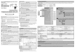
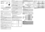
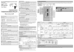
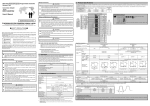
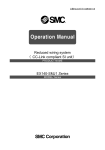
[Installation Precautions]
CAUTION
RFID Interface Module
Model
• Use the module in an environment that reflects the general specifications
stated in the manual. Using the module in an environment that does not
comply with the general specifications results in the risk of electric shock, fire,
malfunction, and product damage or deterioration.
• Fully secure the module using a DIN rail or installation screws, and fully tighten
the screws within the specified torque range. If a screw is too loose, a dropped
module, short circuit, or malfunction may result. If a screw is too tight, screw
and/or module damage may occur, resulting in a dropped module, short circuit,
or malfunction.
• Do not directly touch a powered section or electronic component of the module.
Doing so results in the risk of module malfunction and failure.
ECL2-V680D1
User's Manual
(Hardware)
[Wiring Precautions]
WARNING
• Be sure to shut off all phases of the external power supply used by the system
before performing work such as wiring. Failure to do so results in the risk of
product damage, and malfunction.
CAUTION
ECL2-V680D1
Model ECL2-V680D1
50CM-D180159-B(1410)MEE
HEAD OFFICE:HULIC KUDAN BUILDING.1-13-5, KUDANKITA CHIYODA-KU, TOKYO 102-0073, JAPAN
NAGOYA ENGINEERING OFFICE:139 SHIMOYASHIKICHO-SHIMOYASHIKI, KASUGAI, AICHI 486-0906, JAPAN
SAFETY PRECAUTIONS
(Always read these precautions prior to use.)
• Ground the noise filter ground terminal to the control panel using the
shortest wire possible (approx. 10cm).
EMC AND LOW VOLTAGE DIRECTIVES
• Be sure to ground the FG terminal using programmable controller dedicated
class D (type 3) grounding or greater. Failure to do so results in the risk of
electric shock and malfunction.
• Be sure to tighten any open terminal screws within the specified torque range.
Failure to do so causes a short circuit.
• Use the appropriate crimp terminals, and tighten the terminals to the specified
torque. If a crimp terminal with an open end is used, the terminal screw will
fall off if loose, causing failure.
• Securely mount the antenna cable to the module connector.
After mounting, check if there is any lifting in the contact.
Poor contact causes erroneous input and output.
• Be sure to secure communication cables and power cables connected to the
module by placing them in a duct or clamping them.
If not, dangling cables may swing or inadvertently be pulled, resulting in damage
to the module or cables, or malfunctions due to poor cable contact.
• When connecting a cable, first verify the connection interface type and then
connect the cable properly.
Connecting a cable to a wrong interface or incorrect wiring a cable results in
the risk of module and external device failure.
• Tighten the terminal screws within the specified torque range.
If a terminal screw is too loose, a short circuit or malfunction may result.
If a terminal screw is too tight, screw and/or module damage may occur,
resulting in a short circuit or malfunction.
• When removing a communication cable or power cable connected to the
module, do not pull the cable section.
For cables with connectors, hold the connector of the section connected to
the module during removal.
For terminal block cables, loosen the screws of the terminal block and then
remove the cable.
Pulling a cable connected to the module results in the risk of module and cable
damage, or malfunctions due to poor cable connection.
• Prevent foreign matter such as dust or wire chips from entering the module.
Such foreign matter may cause fire, failure, or malfunction.
• Do not bunch the control wires and communication cables with the main circuit,
power lines, or the like, or install them close to each other. Keep a distance of
100mm or more between them. Failure to do so may result in malfunction due to noise.
(1) Programmable controller system
When you want to incorporate an EMC Directive and Low Voltage Directive
compliant programmable controller into your product to ensure directive compliance,
refer to the user's manual of the CPU or head module used.
A programmable controller that is compliant with the EMC Directive and Low
Voltage Directive has a CE mark printed on the rating plate of the main unit.
• Authorized representative in Europe
The authorized representative in Europe is shown below.
Company name: Mitsubishi Electric Europe B.V.
Address: Gothaer strasse 8, 40880 Ratingen, Germany
(2) About this product
To make this product compliant with the EMC Directive and Low Voltage Directive,
the following countermeasures are required.
1) External power supply
• For the external power supply, use a CE mark compatible product and be
sure to ground the FG terminal.
• Make the length of the power line connected to the module power supply
terminal 10m or less.
2) CC-Link
• Be sure to ground the shield of cables connected to a CC-Link module or
each CC-Link station near the outlet from the control panel within 30cm
from the module or station.
The CC-Link dedicated cable is a shielded cable.
Remove a portion of the outer sheath
as shown below, and ground the
exposed shield section across as
CC-Link
wide an area as possible.
dedicated cable
• For CC-Link dedicated cables,
Shield
always use the specified cable.
• Connect the CC-Link module and each CC-Link station with the FG line
inside the control panel using the FG terminal as shown below.
Master module
Remote module
Local module
(Blue)
(Blue)
(Blue)
DA (Blue)
DA
DA
(White)
(White)
(White)
(White)
DB
DB
Terminating
(Yellow)
(Yellow)
(Yellow) DB Terminating
(Yellow)
DG
DG
DG resistor
resistor
SLD
SLD
SLD
CC-Link
CC-Link
FG
FG
FG
dedicated cable
dedicated cable
• Use a CE mark compatible product for the power supply connected to the module
power supply and external power supply. Be sure to ground the FG terminal.
3) Ferrite core
A ferrite core is effective for reducing noise in the band of 30MHz to 100MHz.
In the event an adequate cable shielding effect is not achieved by the shielded
cable drawn outside the control panel, ferrite core mounting is recommended.
Mount the ferrite core just before the point where the cable is routed outside
the cabinet. The ferrite will not be effective if the mounting position is not
adequate. Attach the ferrite core to the terminal that connects to the external
power supply of the main module, 4cm away from the module.
Before using this product, please read this manual and the relevant
manuals introduced in this manual carefully and pay full attention to
safety to ensure that the product is handled correctly.
Mounting example
The precautions presented in this manual are concerned with this product only.
For programmable controller system safety precautions, refer to the
user’s manual of the CPU module used.
In this manual, the safety precautions are classified into two levels:
"WARNING" and "CAUTION".
Product Application
indicates that incorrect handling may cause
+24V
(1) This Mitsubishi Electric Engineering Company Limited (hereinafter referred to
conditions, leading to death or
WARNING hazardous
as "MEE") product shall be used in applications that will not lead to a major
severe injury.
accident even in the unlikely event any failure or defect should occur in the
24G
indicates that incorrect handling may cause
product in which this Mitsubishi product is incorporated, and shall be systematically
conditions, leading to minor or
provided with external backup and fail-safe functions that operate in the event
CAUTION hazardous
moderate injury or property damage.
of any failure or defect.
(2) This Mitsubishi product has been designed and manufactured as a general
Ferrite core
Under some circumstances, failure to observe the precautions given
purpose product for general industry applications and the like.
under " CAUTION" may lead to serious consequences. Observe the
Thus, the product shall be excluded from use in special equipment, system, and 4) Noise filter (power supply line filter)
precautions of both levels because they are important for personal safety.
other applications such as those listed below. If used in such applications, Mitsubishi
The noise filter is a product that effectively reduces conducted noise.
Keep this manual in an easy to access location for future reference,
shall not bear any responsibility whatsoever for the quality, performance, and safety
Installing a noise filter makes it possible to suppress the noise.
and be sure to provide the manual to the end user.
of the Mitsubishi product (including but not limited to non-performance of main obligation,
(The noise filter is effective for reducing conducted noise in the band of 10MHz or less.)
defect liability, quality assurance liability, tort liability, and product liability):
Connect the noise filter to the external power supply of the main module
[Design Precautions]
• Applications in which the public could be greatly affected such as the applications
and to the external power supply of the extension module.
of the nuclear and other power plants operated by the respective power companies
CAUTION
Use a noise filter that has the same attenuation characteristics as the TDK
• Applications in which a special quality assurance system is required, such
Corporation product MA1206. This is not required, however, if the product
• If a data link communication error occurs, the data of the master
as the applications of railway companies or government or other public offices
is used in Zone A defined in standard EN61131-2.
module will be retained. Using the communication status information,
• Use in aircraft, medical applications, railway applications, incineration and
The precautions required when installing a noise filter are described below.
configure an interlock circuit in the sequence program to ensure that
fuel devices, passenger vehicles, manned transport devices, equipment for
• Do not bundle the wires on the input side and output side of the noise filter.
the system will operate safely.
recreation and amusement, and safety devices, in which human life or assets
When the wires are bundled, the output side noise will be introduced into
• Any of the remote I/O signals marked "Use prohibited" are used by
could be greatly affected
the input side wires from which the noise was filtered.
the system. Do not use these signals. In the unlikely event such a signal
Note that such an application of the Mitsubishi product may be permitted as
Input side
Input side
is used (ON/OFF), the function of the module cannot be guaranteed.
(power supply side) (power supply side)
determined by Mitsubishi if the user accepts that the application is to be limited
• When installing the RFID interface module and amplifier or antenna
and
a
special
quality
is
not
to
be
required
(a
quality
that
exceeds
the
general
cable, do not bundle the cables with or install the cables close to
specifications). For details, please consult with Mitsubishi.
the main circuit, power lines, CC-Link cables, or the like.
Be sure to separate the cables and lines by about 100mm or more.
Manuals
Failure to do so will cause noise, resulting in malfunction.
The manuals related to this product include the following.
Introduction
• When storing the product, be sure to observe the defined storage
Feel
free
to
order
the
manual
if needed.
ambient temperature and humidity. Failure to do so will lead to module
Filter
Filter
Detailed
manuals
malfunction and failure.
Output side
Output side
• Lock the control panel so that only those who are trained and have
(device side)
(device side)
Manual Number Standard
Manual Title
acquired enough knowledge of electric facilities can open the control
Price
panel.
ECL2-V680D1 RFID Interface Module
Noise will be introduced when the
Separate the input and output wires.
• Install the emergency stop switch outside the control panel so that
50CM-D180160 ¥3,000
User's Manual (Details)
input and output wires are bundled.
workers can operate it easily.
No.
• YNT-2216 (JST Mfg. Co., Ltd.),
T-212 (Nippon Tanshi Co., Ltd.),
NH11 (Nichifu Co., Ltd.)
Applicable Compression [compatible wire size : AWG20 to 16]
tools for wire connectors • YNT-1614 (JST Mfg. Co., Ltd.),
T-221N (Nippon Tanshi Co., Ltd.),
NH12 (Nichifu Co., Ltd.)
[compatible wire size : AWG16 to 14]
Description
On: Power on Off: Power off
On: Operating normally in RUN mode.
RUN
Flashing: Operating normally in TEST mode.
Off: When a watchdog timer error occurs.
L.RUN
On: Data link is being executed.
SD
On: Transmitting data.
RD
On: Receiving data.
On: Communication data error
Incorrect setting switch of Station number
or link speed.
Display
Flashing
(Regular interval)
LED
:When the switch of Station number or link
L ERR.
speed was changed while the power was ON.
Flashing (Irregular interval)
:•Un attached the terminator
•The cable is disconnected or the transmission
path is effected by noise.
Off: Operating normally
BSY. On: Operating Off: Standby
RFID NOM. On: Communication ended normally
Off: Standby or abnormal end
I/F
ERR. On: Error Off: Normal
Used to set the 10's place of the station number using
station numbers "10", "20", and "40".
Used to set the 1's place of the station number using
station numbers "1", "2", "4", and "8".
Station
Always set the station number within the range of 1 to 64.
number
(Example) When the station number is set to "32", the
setting
switch is set as follows.
switch
Station
10's Place
1's Place
No.
40
20
10
8
4
2
1
32
OFF ON ON OFF OFF ON OFF
Set
Transmission
Setting Switch
Speed
Value
4
2
1
0
OFF
OFF
OFF
156kbps
Transmission
speed
1
OFF
OFF
ON
625kbps
setting
2
OFF
ON
OFF
2.5Mbps
switch
3
OFF
ON
ON
5.0Mbps
4
ON
OFF
OFF
10Mbps
Always set the transmission speed in the range above.
PW
1)
2)
4. MOUNTING AND INSTALLATION
4.1 Usage Precautions
(1) The RFID interface module case is made of plastic. Do not drop
the case or expose the case to strong impact.
(2) Before touching the module, be sure to touch grounded metal or
the like to release the static electricity from your body.
(3) Tighten the module screws, etc., within the ranges described below.
A loose screw results in the risk of a short circuit, module failure,
and malfunction.
Tightening
Screw Location
Torque Range
Module installation screw (M4 screw)
0.79 to 1.08N•m
0.42 to 0.58N•m
Terminal block terminal screw (M3 screw)
0.68 to 0.98N•m
Terminal block installation screw (M3.5 screw)
Name
3)
4)
4.2 Installation Environment
Refer to the user's manual of the CPU module used.
Transmission
/module
power
supply
terminal
block
4.3 Cable Installation
When installing the antenna cable to the RFID interface module, install
the cable without applying excessive external force to the connecting
section of the module connector.
5 45 3.5
150
30
30
5)
Reset
switch
Set Value
Setting Switch
DA
DB
CC-Link dedicated cable terminal
DG
SLD
FG
Class D (type 3) grounding terminal
+24V
External power supply terminal
24G
Resets the module when the CC-Link transmission
speed setting was changed, the station number was
changed, the mode was switched, or a hardware or
WDT error occurred, initializing ECL2-V680D1.
65
30
Data
Set CC-Link No. of Extended Transfer
Occupied Cyclic
Value
Ver.
Stations Setting Size
0
R1
6
φ3.4
1
2
3
90
100
3.
R4
6)
0
Cable bending radius:
13.6mm or greater
Cable bending radius:
40mm or greater
5. PART NAMES AND SETTINGS
7)
8)
9)
5)
6)
9)
7)
8)
4
5
6
7
8
9
A
B
C
D
E
F
The following describes the names of the parts of the RFID interface module.
8)
1)
2)
3)
4)
Mode
switch
Ver. 1
4
compatible stations
16 words
RUN/
TEST
Mode
6. WIRING
(1) Do not wire the cables near or bundle the cables with main circuit cables,
high voltage lines, or load lines other than those of the programmable controller.
Doing so causes noise and surge impact, resulting in the risk of malfunction.
At the very least, separate the module cables from the above by 100mm or more.
(2) When using a group of equipment, such as inverters, server motors,
and the like, be sure to execute class D grounding (type 3 grounding).
Failure to do so results in the risk of magnetic field interference from the
main body and cable and malfunction.
(3) Do not invert the external power supply polarities.
The RFID interface module will not operate.
6.2 Wiring the External Power Supply Terminal
Wire the external power supply terminal as shown on
the right.
(Connection example)
Connect the 24V DC power supply to
the power supply below.
+24V 24G
A circuit (class 2 circuit) having a class 2 power supply module in
accordance with UL1310 or a class 2 transformer in accordance with UL1585
as a power supply, and a maximum voltage of 30Vrms (42.4 peak) or less.
While simply corrective action within the RFID interface
module is sufficient to counter the noise superimposed on
the power line, the noise to the ground can be significantly
reduced by supplying power via a line filter.
Line filter
+DC24V
+24V
24G
24G
When inserting or removing an antenna or cable, follow the procedures below.
(1) Insertion Method
[1] Hold the section of the connector that secures the cable and insert
the connector with the white dot facing upward.
[2] Push the connector straight in until the connector locks.
Item
Operating ambient
temperature
Storage ambient
temperature
Operating ambient
humidity
Storage ambient
humidity
Specifications
0 to 55°C
-20 to 75°C
10 to 90% RH, non-condensing
10 to 90% RH, non-condensing
Frequency Acceleration Amplitude
Vibration
resistance
Sweep
Count
With
JIS B 3502
3.5mm 10 times each
5 to 8.4Hz
in X, Y, Z
intermittent
and
8.4
to
150Hz
9.8m/s
directions
vibration
IEC 61131-2
compliant
With
1.75mm
5 to 8.4Hz
continual
vibration 8.4 to 150Hz 4.9m/s
JIS B 3502 and IEC 61131-2 compliant
(147m/s2; 3 times each in X, Y, and Z directions)
Impact
resistance
Operating
Free of corrosive gasses
environment
0 to 2000m
Operating altitude*1
Installation location
Inside control panel *4
Overvoltage
II or less
category*2
2 or less
Pollution degree*3
*1: Do not use or store the programmable controller under pressure higher than the
atmospheric pressure of the altitude 0m. Doing so may cause malfunction.
*2: This indicates the section of the power supply to which the equipment is
assumed to be connected between the public electrical power distribution
network and the machinery within the premises. Category II applies to
equipment for which electrical power is supplied from fixed facilities. The surge
voltage withstand level for up to the rated voltage of 300V is 2500V.
*3: This index indicates the degree to which conductive material is generated in
terms of the environment in which the equipment is used. Pollution level 2 is
when only non-conductive pollution occurs. A temporary conductivity caused
by condensing must be expected occasionally.
*4: An environment other than inside the control panel is also applicable if the
environment satisfies conditions such as the operating ambient temperature
and operating ambient humidity.
3. PERFORMANCE SPECIFICATIONS
The following describes the performance specifications of the RFID interface module.
Item
Specifications
Model name
ECL2-V680D1
Connectable antenna
V680-HA63A+V680-HS□□
manufactured by Omron
V680-HA63B+V680-HS□□
Corporation
V680-H01-V2
1 antenna
No. of connectable antennas
CC-Link station type
Device station
CC-Link version
Ver. 1.10 and Ver. 2.0
Station number With two occupied stations: Station numbers 1 to 63
selections
With four occupied stations: Station numbers 1 to 61
Transmission speed 156kbps/625kbps/2.5Mbps/5Mbps/10Mbps (selectable)
Extended Data transfer
Number of
CC-Link
cyclic
occupied
version
volume
setting
stations
No. of occupied
CC-Link stations and
2 stations
8 words
Ver.1.10
side
4 stations
16 words
data transfer
2X
16 words
volume
Ver.2.0
4X
32 words
2 stations
8X
64 words
Ver. 1.10 compatible CC-Link dedicated cable
CC-Link dedicated cable (Ver. 1.00 compatible)
Connection
CC-Link dedicated high performance cable
cable
(Ver. 1.00 compatible)
20.4 to 26.4V DC (24V DC -15%, +10%)
(ripple rate: within 5%)
External power supply
Current consumption: 0.33A or less (with 24V DC)
Please confirm the following product warranty details prior to
product use.
Gratis Warranty Terms and Gratis Warranty Range
If any fault or defect (hereinafter referred to as "Failure")
attributable to MEE should occur within the gratis warranty period,
MEE shall repair the product free of charge via the distributor from
whom you made your purchase.
Gratis Warranty Period
The gratis warranty period of this product shall be one (1)
year from the date of purchase or delivery to the designated
place. Note that after manufacture and shipment from MEE,
the maximum distribution period shall be six (6) months, and
the gratis warranty period after manufacturing shall be limited
to eighteen (18) months.
In addition, the gratis warranty period for repaired products
shall not exceed the gratis warranty period established prior
to repair.
Gratis Warranty Range
The gratis warranty range shall be limited to normal use based
on the usage conditions, methods and environment, etc.,
defined by the terms and precautions, etc., given in the
instruction manual, user's manual and caution labels on the
product.
Do not insert the connector with the power supply on.
Doing so results in the risk of failure.
The connector will not lock if you push the ring section.
Be sure to hold and push the section that secures the cable.
(1) MEE shall offer product repair services (fee applied) for
seven (7) years after production of the product has been
discontinued. Discontinuation of production shall be reported
via distributors.
(2) Product supply (including spare parts) is not possible after
production has been discontinued.
Section that
secures the cable
Exclusion of Opportunity Loss and Secondary Loss
from Warranty Liability
Ring section
(2) Removal method
[1] Hold onto the ring section and pull straight back.
CAUTION
RUN
mode
The connector cannot be removed by holding and
pulling the section that secures the cable.
Pulling that section results in the risk of breakage and
damage. Do not pull the cable with force.
Do not remove the connector with the power on.
Doing so results in the risk of failure.
Regardless of the gratis warranty period, MEE shall not be
liable for compensation for damages arising from causes not
attributable to MEE, opportunity losses or lost profits incurred
by the user due to Failures of MEE products, damages or
secondary damages arising from special circumstances, whether
foreseen or unforeseen by MEE, compensation for accidents,
compensation for damages to products other than MEE products,
or compensation for other work carried out by the user.
Changes in Product Specifications
Section that
secures the cable
Use prohibited
Ver. 1
compatible
2. GENERAL SPECIFICATIONS
Warranty Period after Discontinuation of Production
6.3 Inserting and Removing the Antenna and Cable
CAUTION
This user's manual describes the specifications, part names, installation,
wiring and connections with other devices, and other information related
to the ECL2-V680D1 CC-Link OMRON V680 series compatible RFID interface
module (hereinafter "RFID interface module") used as a CC-Link system
remote device station.
Once you have opened the product package, verify that the package contains
the following.
Item
Quantity
RFID interface module
1
Manual
1
1
Ferrite core
Crimp terminals (Red) (Compatible wire size : AWG20 to 16)
13
Crimp terminals (Blue) (Compatible wire size : AWG16 to 14)
13
Product Warranty Details
6.1 Wiring Precautions
The specifications given in the catalogs, manuals and technical
documents are subject to change without notice.
Ring section
8 words
RUN
2x
16 words mode
4x
32 words
8x
64 words
Test details
Communication test
TEST
Distance level measurement
mode
Noise level measurement
2
Ver. 2 stations
compatible
7. EXTERNAL DIMENSIONS
Use prohibited
Antenna
connector A connector for antenna connection.
Module
installation Screw holes for installing the module.
screw holes
DIN rail
A hook for installing the DIN rail.
hook
45
150
65
Specifications
DC-type noise voltage 500Vp-p, noise width 1μs, based on
a noise simulator with a noise frequency of 25 to 60Hz
Withstand voltage
All DC external terminals – Ground: 500V DC, 1 minute
All DC external terminals – Ground: 500V DC,
Insulation resistance
10MΩ using insulation resistance tester
IP2X
Protection level
65(H) 150(W) 45(D)[mm]
Outer dimensions
0.3kg
Weight
7-point 2-piece terminal block
External Communication
[transmission
circuit,
module
power supply, FG]
area,
module
connection
M3 x 5.2 screws (tightening torque range: 0.42 to 0.58Nm)
method power supply No. of inserted compatible crimp terminals: 2 or less
area
M4 screw with plain washer finished round
Module installation
(tightening torque range: 0.79 to 1.08N•m)
screws
DIN rail installable, installable in 6 directions
TH35-7.5Fe, TH35-7.5Al (JIS C 2812 compliant)
Applicable DIN rail
• N1.25-3 (JST Mfg. Co., Ltd.)
Applicable crimp
[compatible wire size : AWG20 to 16]
terminals
• N2-MS3 (JST Mfg. Co., Ltd.)
[compatible wire size : AWG16 to 14]
Item
Noise resistance
1. OVERVIEW
Unit: mm
This document is a new publication, effective October 2014.
Specifications are subject to change without notice.
The standard price does not include consumption tax.
Please note that consumption tax will be added at the time of
purchase.
Developed October 2014
50CM-D180159-B