1
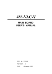
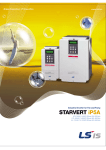
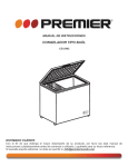
User Manual AT-200CL Digital 3CCD Progressive Scan RGB Color Camera Document Version: RC AT-200CL_Ver.1.0_Oct09 1009E-0908 AT-200CL Notice The material contained in this manual consists of information that is proprietary to JAI Ltd., Japan and may only be used by the purchasers of the product. JAI Ltd., Japan makes no warranty for the use of its product and assumes no responsibility for any errors which may appear or for damages resulting from the use of the information contained herein. JAI Ltd., Japan reserves the right to make changes without notice. Company and product names mentioned in this manual are trademarks or registered trademarks of their respective owners. Warranty For information about the warranty, please contact your factory representative. Certifications CE compliance As defined by the Directive 2004/108/EC of the European Parliament and of the Council, EMC (Electromagnetic compatibility), JAI Ltd., Japan declares that AT-200CL complies with the following provisions applying to its standards. EN 61000-6-3 (Generic emission standard part 1) EN 61000-6-2 (immunity) FCC This equipment has been tested and found to comply with the limits for a Class B digital device, pursuant to Part 15 of the FCC Rules. These limits are designed to provide reasonable protection against harmful interference in a residential installation. This equipment generates, uses and can radiate radio frequency energy and, if not installed and used in accordance with the instructions, may cause harmful interference to radio communications. However, there is no guarantee that interference will not occur in a particular installation. If this equipment does cause harmful interference to radio or television reception, which can be determined by turning the equipment off and on, the user is encouraged to try to correct the interference by one or more of the following measures: - Reorient or relocate the receiving antenna. - Increase the separation between the equipment and receiver. - Connect the equipment into an outlet on a circuit different from that to which the receiver is connected. - Consult the dealer or an experienced radio/TV technician for help. Warning Changes or modifications to this unit not expressly approved by the party responsible for FCC compliance could void the user’s authority to operate the equipment. -2- 1009E-0908 AT-200CL Table of Contents 1. General ....................................................................................... - 5 2. Camera nomenclature.................................................................... - 5 3. Main Features ............................................................................... - 6 4. Locations and Functions .................................................................. - 7 5. Pin Assignment ............................................................................. - 8 5.1. 12-pin Multi-connector (DC-IN/Trigger) ............................................................... - 8 5.2. Digital Output Connector for Camera Link............................................................ - 8 5.3. DIP switch................................................................................................. - 9 5.3.1 SW-600 .............................................................................................. - 9 5.3.2 SW-100 .............................................................................................. - 9 5.4. Rear Panel indication .................................................................................. - 10 - 6. Input and output circuits ..............................................................- 10 - 6.1. Iris video output ........................................................................................ - 10 6.2. Trigger input ............................................................................................ - 10 6.3. XEEN output ............................................................................................. - 11 6.4. Digital output interface (Camera Link® interface) ................................................ - 11 6.4.1 Digital Output (Bit allocation).................................................................. - 13 6.5. Auto iris video output level ........................................................................... - 13 - 7. Functions and Operations ...............................................................- 14 - 7.1. Basic construction........................................................................................ - 14 7.2. Main functions .......................................................................................... - 14 7.2.1 Partial scan (SC) .................................................................................. - 14 7.2.2 Vertical Binning (VB)............................................................................. - 16 7.2.3 Electronic shutter (SM) .......................................................................... - 16 7.2.4 Auto-detect LVAL-sync / a-sync accumulation .............................................. - 17 7.2.5 Shading compensation (SDM) ................................................................... - 18 7.2.6 White balance (WB) .............................................................................. - 19 7.2.7 Linear matrix (CMTX) ............................................................................ - 19 7.2.8 Blemish compensation (BLM) ................................................................... - 20 7.2.9 Gamma setting (LUTC) .......................................................................... - 20 7.2.10 Knee compensation (KN)....................................................................... - 20 7.2.11 Test pattern generator......................................................................... - 21 7.2.12 Center marker ................................................................................... - 21 - 8. Sensor Layout and timing ..............................................................- 22 - 8.1. CCD Sensor Layout ..................................................................................... - 22 8.2. Normal continuous mode timing ..................................................................... - 23 8.2.1 Horizontal timing................................................................................. - 23 8.2.2 Vertical timing .................................................................................... - 23 8.3. Partial scan timing ..................................................................................... - 24 8.3.1 Horizontal timing................................................................................. - 24 8.3.2 Vertical timing .................................................................................... - 24 8.4. Vertical binning......................................................................................... - 25 8.4.2 Horizontal timing.................................................................................. - 26 - 9. Operation Modes.........................................................................- 26 - 9.1. Continuous operation .................................................................................. - 26 9.2. Edge Pre-select Trigger Mode ........................................................................ - 27 9.2.1 EPS timing ......................................................................................... - 28 9.2.2 EPS timing LVAL sync details ................................................................... - 28 9.2.3 EPS timing LVAL async details.................................................................. - 29 9.3 Pulse Width Control Trigger Mode ............................................................... - 30 9.3.1 PWC timing ........................................................................................ - 30 - -3- AT-200CL 9.3.2 PWC timing - LVAL sync details ................................................................ - 31 9.3.3 PWC timing - LVAL async details............................................................... - 31 9.4. Reset Continuous Trigger (RCT)...................................................................... - 32 9.5. Smearless mode ........................................................................................ - 33 9.6. Trigger mask ............................................................................................ - 33 9.7. Mode and functions matrix ........................................................................... - 33 - 10. Configuring the Camera ............................................................... - 34 10.1. RS-232C control ....................................................................................... - 34 10.2. Communication setting. ............................................................................. - 34 10.3. AT-200CL command list................................................................................ - 35 - 11. Camera Control Tool for AT-200CL ................................................. - 38 11.1. Software installation ............................................................................... - 38 11.2. Run the software.................................................................................... - 38 11.3. Camera Control screen............................................................................. - 38 11.4. LUT set up............................................................................................ - 40 11.5. Menu .................................................................................................. - 41 11.5.1 File Menu......................................................................................... - 41 11.5.2 Settings menu ................................................................................... - 42 11.5.3 Gamma menu ................................................................................... - 42 11.5.4 Help ............................................................................................... - 42 - 12. External Appearance and Dimensions ............................................ - 43 13. Specifications ............................................................................ - 44 - 13.1. Spectral sensitivity for sensor ........................................................................ - 44 13.2. Specification table ..................................................................................... - 45 - 14. Appendix................................................................................. - 47 - 14.1. Precautions ............................................................................................. - 47 14.2. Typical Sensor Characteristics....................................................................... - 47 14.3. Caution when mounting a lens on the camera .................................................... - 47 14.4. Caution when mounting the camera................................................................ - 48 14.5. Exportation ............................................................................................. - 48 14.6. References............................................................................................... - 48 - Change tracking .............................................................................. - 49 User's Record ................................................................................. - 50 - -4- AT-200CL 1. General The AT-200CL is a digital 3CCD progressive scan RGB color camera. It employs three 1/1.8 inch 1628(h) x 1326(v), 2 Megapixel CCDs and it runs 20 frames per second in full resolution mode. The AT-200CL has a Camera Link® interface and its output can be either 8-bit through a Camera Link Base configuration or 10-bit or 12-bit through a Camera Link Medium configuration. JAI developed a new 1/1.8-inch compact F4.0 prism optical system and in combination with a linear color matrix, the AT-200CL provides a higher fidelity of color reproduction. The AT-200CL also incorporates a shading circuit, gamma correction circuit and knee correction circuit to provide high picture quality. Functions like partial scanning and vertical binning allow higher frame rates. The latest version of this manual can be downloaded from: www.jai.com The latest version of Camera Control Tool for AT-200CL can be downloaded from: www.jai.com For camera revision history, please contact your local JAI distributor. 2. Camera nomenclature The standard camera composition consists of the camera main body and C-mount protection cap. The camera is available in the following versions: AT-200CL Where A stands for "Advanced" family, T stands for "3 CCD", 200 represents the resolution "2 million pixels" , and CL stands for "Camera Link" interface. -5- AT-200CL 3. Main Features • • • • • • • • • • • • • • • • • • • • • 3 x 1/1.8” CCD progressive scan RGB color camera for vision applications 3 x 1628(h) x 1236 (v) 4.4µm effective square pixels Compact RGB prism for C-mount lenses Chromatic shading reduction permits wider choice of lenses 20.31 frames per second with 1628 (h) x 1236 (v) pixels 79.23 fps with 1628 (h) x 152 (v) pixels in 1/8 partial scan In addition to fixed rate partial scan, variable partial scan is available Vertical binning for higher sensitivity and frame rate of 35.93 fps 8-bit RGB output via single port Camera Link. 10-bit or 12-bit via dual port Gamma is selectable for 0.45 or 0.6 or LUT Linear matrix circuit with sRGB or Adobe RGB pre-setting Knee function available for knee point and knee slope settings. Blemish compensation ON/OFF available Noise reduction circuit built in Edge Pre-select, Pulse Width Control and Reset Continuous Trigger modes Smearless mode available for EPS and PWC Pre-set shutter in the range from OFF(1/20) and 1/60 to 1/51,000, 11 steps Common or individual programmable exposure for RGB Manual, continuous, one push or pre-set white balance Analog iris video output for lens iris control Setup by Windows XP software via RS 232C -6- AT-200CL 4. Locations and Functions ④ ⑤ POWER/ TRIG DC IN / TRIG / ⑥ ③ DIGITA I/O DIGITAL I 2 ② I DIGITAL I/O 1 ① 1. Lens mount 2. Connector 3. Connector 4. 12 pin connector 5. LED 6. Mounting holes *1) Note: *2) Note: *3) Note: Lens mount of C-mount type. *1) Camera Link base connector 1 *2) Camera Link medium connector 2 *2) for DC power and trigger Power and trigger indication 8 x M3 depth 5mm for tripod mount plate or direct installation *3) Applicable C-mount lens should be designed for 3-CCD cameras. Rear protrusion on C-mount lens must be less than 4mm. Be advised: when using a lens with the iris diaphragm fully open, vignetting on corners may occur. When a Camera Link® cable is connected to the camera, please do not excessively tighten screws by using a driver. The Camera Link® receptacle on the camera might be damaged. For security, the strength to tighten screws is less than 0.291 Newton meter (Nm). Tightening by hand is sufficient in order to achieve this. The tripod adapter plate MP-41 can be used. Fig. 1. Locations -7- AT-200CL 5. Pin Assignment 5.1. 12-pin Multi-connector (DC-IN/Trigger) Type: HR10A-10R-12PB-01 (Hirose) male. (Seen from rear of camera.) 9 1 2 8 10 11 3 4 Pin no. 1 2 3 4 5 6 7 8 9 10 11 12 7 12 5 6 Fig. 2. 12-pin connector. Signal Remarks GND +12 V DC input GND Continuous and RCT modes only Iris video GND GND Negative logic XEEN out *1) Trigger in GND *1) 75 ohm termination can be selected by DIP SW600. 5.2. Digital Output Connector for Camera Link 13 1 26 14 Type: 26 pin MRD connector 3M 10226-1A10JL Fig. 3. Camera Link connector The digital output signals follow the Camera Link standardized multiplexed signal output interface. Camera Link base configuration is used for 3 x 8-bit RGB signal and medium configuration is used for 3 x10-bit or 3 x12-bit. The interface circuit is build around the NS type DS90CR285MTD. Port 1 (24bits, 30 bits, 36 bits) Pin No In/Out 1,14 2(-),15(+) O 3(-),16(+) O 4(-),17(+) O 5(-),18(+) O 6(-),19(+) O 7(+),20(-) I 8(-),21(+) O 9(-),22(+) I 10(+),23(-) I 11,24 12,25 13,26 Name Shield TxOUT0 TxOUT1 TxOUT2 TxClk TxOUT3 SerTC (RxD) SerTFG (TxD) CC1 (Trigger) CC2 (Reserved) N.C. N.C. Shield -8- Note GND Data out Clock for CL Data out LVDS Serial Control JAI Standard Trigger GND AT-200CL Port2 (30bits, 36bits) Pin No 1,14 2(-),15(+) 3(-),16(+) 4(-),17(+) 5(-),18(+) 6(-),19(+) 7(+),20(-) 8(-),21(+) 9(-),22(+) 10(+),23(-) 11,24 12,25 13,26 In/Out O O O O O Name Shield TxOUT0 TxOUT1 TxOUT2 TxClk TxOUT3 N.C. N.C. N.C. N.C. N.C. N.C. Shield Note GND Data out Clock for CL Data out GND 5.3. DIP switch 5.3.1 SW-600 This switch can select ON or OFF of 75 ohm termination for trigger input. The factory default setting is OFF which is TTL level. No 1 2 Setting Functions Trigger input termination NC ON OFF TTL - 75Ω - 5.3.2 SW-100 This switch can select the type of the signal which is output through 12-pin #10. The factory default is TTL (XEEN) and it can be changed to Open collector (EEN). No 1 2 Functions EEN output select NC Setting ON Open collector (EEN) - ON ON Fig.4. SW600 (On rear panel) OFF TTL(XEEN) - Fig.5. SW100(Right board looking from the front) -9- AT-200CL 5.4. Rear Panel indication The rear panel mounted LED provides the following information: z Amber : Power connected - initiating z Steady green : Camera is operating in Continuous mode Æ Flashing green : The camera is receiving external trigger POWER / TRIG DC IN / TRIG DIGITAL I / O - 2 DIGITAL I / O - 1 Fig.6. rear panel 6. Input and output circuits This chapter introduces the basic diagram and bit allocation of digital output. 6.1. Iris video output This signal can be used for lens iris control In Continuous and RCT modes. The signal is NUM luminance signal and passes through the gain circuit. However, due to reversed compensation applied, the gain settings do not influence this signal. The iris video output is 0.7 V p-p from 75 Ω and without sync. This signal is always output except EPS and PWC modes. Fig. 7. Iris video output. 6.2. Trigger input When TI=1, the trigger input is on pin #10 on the 12-pin connector. The input is AC coupled. To allow a long pulse width, the input circuit is a flip-flop, which is toggled by the negative or positive differentiated spikes caused by the falling or rising trigger edges. The trigger polarity can be changed by TP=1. Trigger input level is 4 V ±2 V. It can be terminated by SW600 : ON for 75Ω. OFF for TTL. The trigger inputs can be changed to Camera Link. (TI=0 for CL) Fig. 8. Trigger input. - 10 - AT-200CL 6.3. XEEN output XEEN is found on pin #9 on 12-pin HR connector. The output circuit is 75 Ω complementary emitter followers. Output level ≥3 V from 75Ω. (No termination). When the open collector is used, the maximum current is 120mA. However, if the current of more than 50mA is flowed, it is necessary to use bigger diameter wires for connecting pin#8 and 9. In case of narrower wires, due to its resistance, it may not work properly. This output can be changed to Open collector signal by SW100. EEN is found in Camera Link. It is high during exposure. Fig.9. EEN output 6.4. Digital output interface (Camera Link® interface) The video output is Camera Link with 3 x 8 bits RGB video placed in a base configuration, or 3 x 10 bits or 3 x 12 bits RGB placed in a Camera Link medium configuration. The digital output signals follow the Camera Link standardized multiplexed signal output interface. The Camera Link output driver is NS type DS90CR285MTD. The data bits from the digital video, FVAL, LVAL, DVAL and EEN are multiplexed into the twisted pairs, which are a part of the Camera Link. Trigger signals and the serial camera control are fed directly through its own pairs. The trigger input can also be TTL on the 12-pin connector. For details of the Camera Link® standard, visit the AIA web site www.machinevisiononline.org. 6.4.1 Camera Link® bit allocation The AT-200CL outputs an RGB signal via Camera Link. A 3 x 8-bit signal is allocated via a Base configuration through port 1, while a 3 x 10-bit or 3 x 12-bit signal is allocated via a Medium configuration through both port 1 and port 2. On the next page, there is bit allocation table. RD9~RD0 : R Channel Camera Data(RD9=MSB, RD0=LSB) GD9~GD0 : G Channel Camera Data(GD9=MSB, GD0=LSB) BD9~BD0 : B Channel Camera Data(BD9=MSB, BD0=LSB) × : Not in use - 11 - AT-200CL Port/Signal Port A0 Port A1 Port A2 Port A3 Port A4 Port A5 Port A6 Port A7 Port B0 Port B1 Port B2 Port B3 Port B4 Port B5 Port B6 Port B7 Port C0 Port C1 Port C2 Port C3 Port C4 Port C5 Port C6 Port C7 Port D0 Port D1 Port D2 Port D3 Port D4 Port D5 Port D6 Port D7 Port E0 Port E1 Port E2 Port E3 Port E4 Port E5 Port E6 Port E7 Port F0 Port F1 Port F2 Port F3 Port F4 Port F5 Port F6 Port F7 LVAL FVAL DVAL EEN 24 bits output 30 bits output 36 bits output RD0 RD1 RD2 RD3 RD4 RD5 RD6 RD7 GD0 GD1 GD2 GD3 GD4 GD5 GD6 GD7 BD0 BD1 BD2 BD3 BD4 BD5 BD6 BD7 × × × × × × × × × × × × × × × × × × × × × × × × RD0 RD1 RD2 RD3 RD4 RD5 RD6 RD7 RD8 RD9 × × BD8 BD9 × × BD0 BD1 BD2 BD3 BD4 BD5 BD6 BD7 × × × × × × × × GD0 GD1 GD2 GD3 GD4 GD5 GD6 GD7 GD8 GD9 × × × × × × RD0 RD1 RD2 RD3 RD4 RD5 RD6 RD7 RD8 RD9 RD10 RD11 BD8 BD9 BD10 BD11 BD0 BD1 BD2 BD3 BD4 BD5 BD6 BD7 GD0 GD1 GD2 GD3 GD4 GD5 GD6 GD7 GD8 GD9 GD10 GD11 - 12 - Connector Pin No. Port 1 Port 1 Port 1 Port 1 Port 1 Port 1 Port 1 Port 1 Port 1 Port 1 Port 1 Port 1 Port 1 Port 1 Port 1 Port 1 Port 1 Port 1 Port 1 Port 1 Port 1 Port 1 Port 1 Port 1 Port 2 Port 2 Port 2 Port 2 Port 2 Port 2 Port 2 Port 2 Port 2 Port 2 Port 2 Port 2 Port 2 Port 2 Port 2 Port 2 Port 2 Port 2 Port 2 Port 2 Port 2 Port 2 Port 2 Port 2 Port 1/2 Port 1/2 Port 1/2 Port 1/2 Tx0 Tx1 Tx2 Tx3 Tx4 Tx6 Tx27 Tx5 Tx7 Tx8 Tx9 Tx12 Tx13 Tx14 Tx10 Tx11 Tx15 Tx18 Tx19 Tx20 Tx21 Tx22 Tx16 Tx17 Tx0 Tx1 Tx2 Tx3 Tx4 Tx6 Tx27 Tx5 Tx7 Tx8 Tx9 Tx12 Tx13 Tx14 Tx10 Tx11 Tx15 Tx18 Tx19 Tx20 Tx21 Tx22 Tx16 Tx17 Tx24 Tx25 Tx26 Tx23 AT-200CL 6.4.1 Digital Output (Bit allocation) CCD out Analog Signal Digital Out(24bit) Digital Out(30bit) Digital Out(36bit) Black Setup 3.6%, 25mV 8LSB 32LSB 128LSB 200mV 700mV 222LSB 890LSB 3560LSB 800mV 255LSB 1023LSB 4095LSB 230mV↑ Note: The above data is for the case when gamma is OFF. 1023 Wh i te C l ip Leve l 890 D ig i ta l Ou t [LSB ] 100% Leve l B lack Leve l 32 0 25 Ana log S igna l mV [ ] 700 800 Fig.10. Digital output (10bit output) 6.5. Auto iris video output level This video output signal is NUM luminance signal and does not have SYNC. It is available only in Continuous mode and RCT mode. It is also not available in partial scan mode. This signal is not affected by the gain control. CCD out 200mV 230mV↑ Analog Out 700mV 800mV 930 100% Leve l Ana log Ou t mV [ ] 700 0 CCD Ou t mV [ ] 200 265 Fig.11. Iris video output - 13 - AT-200CL 7. Functions and Operations 7.1. Basic construction A 32-bit micro processor controls all functions in the AT-200CL camera. The CCD sensor output is normalized in CDS and preamplifiers. The signals are then digitized to 14 bits. Digital gain control, color matrix, look-up tables and setup can do signal processing in 14 bits before the signal is converted to a 12-, 10- or 8-bit Camera Link signal. Camera Link Interface Fig. 12. Principle diagram for signal processing 7.2. Main functions 7.2.1 Partial scan (SC) The partial scanning function uses the middle of the image vertically to achieve faster frame rates. This is very useful when capturing and inspecting an image which does not require the full height. The AT-200CL has 4 types of pre-set partial scan modes: 2/3, 1/2, 1/4 and 1/8. Fig.13 Partial scan (pre-set) In addition to pre-set partial scan modes, the AT-200CL has a variable partial scan mode. The start line can be set from the 1st line to 1236th line and the end line can also be set from the 1st line to the 1236th line. In actual use, the start line should always be set smaller than the end line and the end line should be larger than the start line. For instance, if the end line is set at 1236, the start line should be 1235 or smaller. If the start line is set at 1, the end line should be set at 2 or larger. - 14 - AT-200CL Fig.14. Variable Partial scan ¡ How to calculate total line number and frame rate in variable partial scan mode Frame rate (fps) = Horizontal frequency(25.432KHz) / Total lines Total lines = OB period + Fast Dump period in the upper part of the frame (L) + Effective image period (L) + Fast dump period in the lower part of frame(L) + Blank period (L) Where, OB period = 4L (Fixed) Blank period = 5L (Fixed) Fast dump period for the upper part = Fast dump period for the lower part = Calculation example Read out: 1/2 partial at the center (621L), Start line (308), End line (928) OB period = 4L Blank period = 5L Fast dump period for the upper part = (5+308-1) ÷7 +1= 44.57 + 1 = 45.57 Æ 46 Fast dump period for the lower part = (1236-928+2) ÷ 7 =44.2 Æ 45 Total lines = 4+5+46+621+45=721 Frame rate = 25,432/ 721 =35.27 fps - 15 - AT-200CL 7.2.2 Vertical Binning (VB) Vertical Binning mode is a function where the signal charges from 2 adjacent (vertical) pixels are added together and read out as one pixel. Binning results in half vertical resolution but higher frame rate and sensitivity. The charge accumulated in 2 adjacent lines is added together in the horizontal CCD register. This is done by providing two pulses to the vertical CCD register for each line read out. Vertical binning cannot be used together with partial scanning. Pixel H Xsg1 H 2 line Vertical Binning Vertical Direction Vertical CCD Register Normal full scanning Video Out Reset S/H Horizontal CCD Register Fig. 15. Vertical Binning Setting Off (No V Binning)) 2:1 V Binning Horizontal Frequency 25.432 KHz 22.563 KHz Effective/total 1236 /1252 618 / 628 Frame rate 20.31 frames/sec. 35.93 frames /sec. 7.2.3 Electronic shutter (SM) The AT-200CL has the following shutter modes. Pre-set shutter(SH) The setting command is from SH=0(OFF) to SH=11(1/51,000) OFF(1/20),1/60,1/100,1/120,1/250,1/500,1/1000,1/2,000,1/4,000,1/7,000,1/17,000 and 1/51,000s Note: The actual exposure uses the programmable exposure (PE) method. When the camera receives a pre-set shutter value, it is converted to a programmable value inside the camera. So, the actual exposure might be slightly different from the pre-set value. Programmable Exposure (PE) The setting command is PE and the exposure time can be controlled from 0L to 1252L in 1 LVAL units (39.32µs). Calculating actual shutter speed requires adding 0.5L to the setting value. This is because there is 0.5L overhead. The resulting range is from 0.5LVAL to 1252LVAL. Setting 1252L is Shutter OFF. The programmable exposure can be set for R, G and B together (SM=1) or individually (SM=2) in EPS mode. - 16 - AT-200CL The shutter speed for each operation mode is shown below. Mode Read Out Minimum shutter speed Continuous Edge Pre-select Full Partial V binning Full Partial V Binning 15.48 µs at PE=0(1/51,000) Maximum shutter speed 39.32µs x 1252L=1 Frame (49.22ms) 20.62 µs at PE=0(1/45,000s) Pulse Width 39.32 µs x 2L+15.48 µs( 0.5L)= 94.12 µs (≒1/10,965s)(Note) 40 Frames ( 2 seconds ) 44.32 µs x 2L + 20.62 µs(0.5L)= 109.26 µs (≒1/9.152s)(Note) Note: In Pulse Width mode, the minimum trigger pulse width requires more than 2LVAL. Auto shutter AT-200CL has an automatic shutter function which sets the video at an appropriate level depending on illumination. Auto shutter range: 1/20 sec to 1/2400 sec 7.2.4 Auto-detect LVAL-sync / a-sync accumulation This function replaces the manual setting found in older JAI cameras. Whether accumulation is synchronous or asynchronous in relation to LVAL depends on the timing of the trigger input. When a trigger is received while FVAL is high (during readout), the camera works in LVALsynchronous mode, preventing reset feed-through in the video signal. There is a maximum jitter of one LVAL period from issuing a trigger and accumulation start. When a trigger is received during FVAL low, the camera works in LVAL-asynchronous mode (no delay) mode. This applies to both Edge Pre-select (EPS) trigger mode and Pulse Width Control (PWC) trigger mode. External Trigger (1) (2) +/- 1 LVAL (3) FVAL (1) In this period camera executes trigger at next LVAL (prevents feed-through noise) (2) Avoid trigger at FVAL transition (+/- LVAL period), as the function may randomly switch between “ next LVAL ” and “ immediate ”. (3) In this period, camera executes trigger immediately ( no delay). Fig.16. Auto-detect LVAL sync/async accumulation - 17 - AT-200CL 7.2.5 Shading compensation (SDM) The AT-200CL implements a digital shading compensation circuit for the white shading which could be caused in the prism or optical system. The whole image is divided horizontally and vertically and uses the center level as the reference. The circuit will compensate the difference between the center and each divided area. The range for compensation is a maximum of 30%. Shading correction mode: SDM 0:OFF, 1:Factory shading, 2:User 1, 3:User2 These are used to load the stored data. Fig.17 Shading compensation In order to calibrate the shading, use RS command, Recalibrate Shading correction. Param. 1 is used to store the calibration data in 0 for User 1 and 1 for User 2. User 1 and User 2 can store only one data set for either color shading or flat shading. Param. 2 can be set to 0 for Flat or 1 for Color and executes the shading correction and the storing of data. Note: Conditions for lens used with AT-200CL In order to get an appropriate picture, it is recommended to use 1/2 inch, 3CCD lenses. Shading is dependent on F value and focal length. Using a wide angle lens or using the lens fully open, will cause the shading characteristics to deteriorate. AT-200CL has two shading compensation circuits. Video Level Video Level 1. Color shading compensation In this mode, the shading is compensated using the G channel as the reference. Adjust R and B channels to match the characteristics of the G channel. Use white balance to match R, G and B levels. Fig.18 Conceptual drawing for color shading compensation Video Level Video Level 2. Flat shading compensation In this mode, each channel can be adjusted to achieve flat characteristics. Fig.19 Conceptual drawing for flat shading compensation - 18 - AT-200CL 7.2.6 White balance (WB) The AT-200CL has 4 white balance modes: manual balance, one push auto white balance, continuous auto white balance and pre-set white balance. The pre-set white balance can be set to 4000K, 4600K or 5600K. The white balance of AT-200CL is set under 7800K lighting in factory. If the camera is started up at the first time, it is 7800K white balance and R and B gain settings are 0. For executing the white balance, the entire image is divided into 64 areas, 8 for horizontal and 8 for vertical. The following drawing is an example of using a 2 x 2 area in the image center. Fig.20 White balance measuring area Continuous One push Manual Tracking range 4,000K to 9,000K 4,000K to 9,000K 4,000K to 9,000K Adjustable range -6dB ~ +6dB -6dB ~ +6dB -6dB ~ +6dB Store the setting value No Yes Yes Note: In continuous mode, if the white part is not enough to make an adjustment, the white balance may not achieve a proper white color. Note: The completion of one push auto white requires a maximum of 5 seconds to complete. 7.2.7 Linear matrix (CMTX) The AT-200CL incorporates a linear color matrix circuit to improve color reproduction. As this circuit processes signals in the linear stage which is before the gamma correction circuit, the gamma circuit does not affect color reproduction. This circuit has: 1. Linear OFF 2. sRGB Standard which HP and Microsoft specify for printer and monitor. This preset is based on this standard. 3. Adobe RGB Standard which Adobe systems specify. This preset is based on this standard. 4. User User can manipulate R, G and B color relationships based on applications. Set the gain for R-R, R-G, R-B, G-R, G-G, G-B, B-R, B-G, B-B to adjust. Important Note: If sRGB or Adobe RGB is used, please note the following procedure. 1) Achieve the white balance under the condition of D65 (6500K) illumination. 2) Gamma should be set at 0.45 and set the linear matrix at either sRGB or Adobe RGB. 3) Monitor should comply with sRGB or Adobe RGB color reproduction capability. - 19 - AT-200CL 7.2.8 Blemish compensation (BLM) The AT-200CL has a blemish compensation circuit. Blemish control (BLM) has 0:OFF, 1:Black, 2:White and 3:Both. When 1, 2 or 3 is selected, the stored factory data can be loaded. Defective Pixel Fig.21 Conceptual drawing for blemish compensation 1023 Wh i te C l ip Leve l 100% Leve l 890 D ig i ta l Ou t [LSB ] 7.2.9 Gamma setting (LUTC) The AT-200CL has various gamma settings including LUT (Look Up Table). Gamma can be set OFF (1.0), 0.6, 0.45, or to exhibit characteristics set using LUT. The following shows the typical characteristics in the case of gamma 0.6. B lack Leve l 32 0 25 Ana log S igna l mV [ ] 700 835 Fig.22. Gamma setting Analog Signal Setup 3.6%, 25mV 700mV 800mV Digital Out(36bit) 128LSB 3560LSB 4095LSB 7.2.10 Knee compensation (KN) If the relation of input and output is linear (1:1), the output signal is saturated at a certain level of the input signal and details cannot be reproduced in the saturated area. The knee compensation circuit maintains linear output up to a knee point and compresses the level after the knee point. This is set by a knee slope function. AT-200CL supports up to 200% signal compression by knee slope. Factory default is OFF. Functions Knee Point Knee Slope Data length 10bit 12bit Digital Out(30bit) 32LSB 890LSB 1023LSB Digital Out(24bit) 8LSB 222LSB 255LSB Video Output CCD out Black 200mV 230mV↑ Fig.17. Example of Knee characteristics Setting range 0LSB ~ 1023LSB 0(x0.0005) ~ 4095(x2.0000) - 20 - AT-200CL 7.2.11 Test pattern generator The AT-200CL has an internal test pattern generator. These signals are output as the last process of the digital signal processing circuit and can be used for adjustment of the related system. The AT-200CL has a total of 15 test pattern types. 7.2.12 Center marker At-200CL is equipped with a center marker generator. The center marker can be selected from three types as described below. 1 = Vertical 2 = Horizontal Note: The center marker is displayed only on full scan mode. Fig. 24 Center marker - 21 - 3 = Both AT-200CL 8. Sensor Layout and timing 8.1. CCD Sensor Layout blank 1688 4 Optical Black 1248 2 1252 Active Pixels 1628(H)x1236(V) 1236 10 Optical Black 1966 Clock 12 48 1628 Read Out(Horizontal) Fig. 25. CCD sensor layout - 22 - 278 blank Read Out (Vertical) AT-200CL 8.2. Normal continuous mode timing 8.2.1 Horizontal timing Fig. 26. Horizontal timing 8.2.2 Vertical timing 1 FVAL per i od AL 1L = 42.07F Vµs 1252L 4L 1248L FVAL LVAL S UB SG 0 .5 L E xp o s u r e Per i od EEN d XEEN 1236L Re s er v e d 1 12 OB 10L Effecti ve Li nes 36 Re s er ve (Hi rose 12pi n) DATA OU T DVAL 1L = 1966Cl ock ( 39. 32us ) (1LVAL Period) OB: Optical black Fig. 27. Vertical timing for full scan - 23 - OB 2 Bl ank 4L L VAL AT-200CL 8.3. Partial scan timing 8.3.1 Horizontal timing Fig.28 Horizontal timing ( Partial scan, the same as normal continuous) 8.3.2 Vertical timing 1 FVAL Period 895L 891L 4L F VAL L VAL Back of frame B a c k o f F r a me Front of frame o High speed transfer S UB SG 0. 5L Exposure period EEN 3L OB 825L 1 1 2 3 4 5 DATA out High speed dump a Effective lines A 31L ( 2/3) Dummy 31L ( 2/3) 4L B C High speed dump DV A L ▪ 1L=1 LVAL period (1966 clock =39.32µs) ▪ OB=Optical black Fig. 29 Vertical timing ( 2/3 partial scan) - 24 - Bl 35L 8 25 (Hirose 12pi n) nk XEEN AT-200CL Option No. of Start End lines line line (Lines) (Line) (Line) 0 Full screen 1 1252 1252 1 2/3 screen 206 1030 825 308 928 621 463 773 541 695 1/2 screen 1/4 3 screen 1/8 4 screen 2 Output image Fu l l Frame Front of Back Blank Frame of Of -AFrame Frame -B-C- 10 2 4 35 31 4 50 46 4 311 72 68 4 155 83 79 4 Par t ia l Scan 8.4. Vertical binning 8.4.1 Vertical timing 1 F VAL Per i od F V A L 628L 624L 4L F VAL L VAL S UB SG 0.5L Exposure period EEN XEEN ( Hi rose 12pi n) OB Ef f ec t i v e L i nes 5L 1L 618 618L 1 2 3 4 5 DATA out DVAL ▪ 1L=1LVAL period (44.32µs) ▪ OB=Optical black Fig.30. Vertical timing for V binning. - 25 - L V A L AT-200CL 8.4.2 Horizontal timing 1 LVAL period 2216 330 LVAL 528 1688 FVAL raising edge FVAL falling edge FVAL 2138 SUB 835 (16.7µs) SG 76 185 120 1020 Exposure Period EEN XEEN (Hirose 12pin) Effective Pixels OB 12 OB 48ck 1628 Dummy+ Blank 5 2 8 ck DATA out DVAL 29ck CCD out 1628 1688 2 9 c k 5 2 8 ck Fig. 31 Horizontal timing for V binning. 9. Operation Modes This 1. 2. 3. 4. 5. camera can operate in 5 primary modes. TR=0 Con Normal continuous Mode TR=1 EPS Edge Pre-select Mode TR=2 PWC Pulse Width Control Mode TR=3 RCT Reset Continuous Mode SL Smearless Mode Pre-selected exposure. Pre-selected exposure. Pulse width controlled exposure. Pre-select exposure 9.1. Continuous operation For applications not requiring asynchronous external triggering, this mode should be used. In this mode it possible to use a lens with video controlled iris. For timing details, refer to fig.26. through fig. 31. To use this mode: Set function: Trigger mode to “Continuous” Scanning Vertical binning Shutter mode normal, programmable Shutter speed Programmable exp. Other functions and settings - 26 - TR=0 SC=0, 1 VB=0, 1 SM=0 through 3 SH=0 through 11 PE=0 through 1252 AT-200CL 9.2. Edge Pre-select Trigger Mode An external trigger pulse initiates the capture, and the exposure time (accumulation time) is the fixed shutter speed set by SH or PE. The accumulation can be automatically set either LVAL synchronous or LVAL asynchronous in relation to FVAL and trigger timing. Refer to chaper 7.2.4 The resulting video signal will start to be read out after the selected shutter time. For timing details, refer to fig27 . through fig35. To use this mode: Set function: Input: Trigger mode to “Edge Pre-select” Scanning Vertical binning Shutter mode to normal or programmable Shutter speed Programmable exp. Other functions and settings Ext. trigger. Camera Link or 12 HiRose TR=1 SC=0, 1 VB=0, 1 SM=0 through 2 SH=0 through 11 PE=0 through 1252 TI=0, TI=1 Important notes on using this mode Active Trigger pulse >2 LVAL to <1 FVAL Minimum Trigger interval is shown in the following table. Mode Minimum trigger interval LVAL Sync 1252L + 1L LVAL Async Exposure time + 1252L + 3L Smearless is ON Smearless time(181L) + Maximum exposure time +1252L + 1L Note: 1) On the above table, 1252L is FVAL interval on normal continuous mode 2) In the vertical binning mode, 1L is different from the normal scanning. So, the minimum trigger interval will be different. - 27 - AT-200CL 9.2.1 EPS timing From most longest channel When the LVAL Sync Accum. : 1.5L When then LVAL Aysnc Accum 1.0 to 2.0L Min:2L~Max:1V ▪ 1 L =1966 clock (39,32 µs) Ext.Trig 1248L FVAL LVAL Rch SUB Rch SG Rch Exposure Period Gch SUB Gch SG Gch Exposure Period Bch SUB Bch SG Bch Exposure Period Same as most shortest channel EEN XEEN Effective lines OB 10L OB 2L 1236L 1236 (Hirose 12pin) 1 2 3 4 5 DATA OUT DVAL Fig.32. Edge Pre-select. 9.2.2 EPS timing LVAL sync details Ext. Tri g FVAL LVAL EEN Expos ur e Pr i od XEEN 1. 5L ( H ir os e 12pi n) ( Exposure) DATA out Dat a out Del ay 11. 5L Exposur e Del ay t 1+1L( Max) Fig.33 Edge Pre-select LVAL SYNC details - 28 - AT-200CL 9.2.3 EPS timing LVAL async details Ext . Tr i g FVAL LVAL Exposure period EEN XEEN 1 to 2L ( Hi r os e 12pi n) (Exposure) Data output delay Exposure delay DATA out 11 t o 12L 9. 7us Fig.34 Edge Pre-select LVAL ASYNC details - 29 - AT-200CL 9.3 Pulse Width Control Trigger Mode In this mode the accumulation time is equal to the trigger pulse width. Here it is possible to have a long time exposure. The accumulation can be automatically set either LVAL synchronous or LVAL asynchronous in relation to FVAL and trigger timing. Refer to chapter 7.2.4. The maximum recommended exposure time is <2 seconds. The resulting video signal will start to be read out after the trigger’s rising edge. For timing details, refer to fig.26 through fig.31 . and fig.35 through fig.37 . To use this mode: Set function: Input: Trigger mode to “Pulse width control”. TR=2 Scanning SC=0 ,1 Vertical binning VB=0, 1 Other functions and settings Ext. trigger. Camera Link or 12 Hirose TI=0, TI=1 Important notes on using this mode Trigger pulse width >2 LVAL to <2 seconds. Minimum trigger interval is shown in the following table. Mode Minimum trigger interval LVAL Sync 1.Exposure time < 1252L 1252L + 3L 2.Exposure time ≥ 1252L Exposure time +2L LVAL Async Exposure time + 1252L +3L Smearless is ON Smearless time (181L) +Exposure time + 1252L + 3L Note: 1) On the above table, 1252L is FVAL interval on normal continuous mode 2) In the vertical binning mode, 1L is different from the normal scanning. So, the minimum trigger interval will be different. 9.3.1 PWC timing 1L=1966 clock (39.32 µs) Mi n: 2L~Max: 40V( 50080L) Ext.Trig 1248L FVAL LVAL SUB t1 SG t2 Exposure Period W h e n t h e L V A L S y n c A c c u m . : t 1 = 0 . 5 t o 1 . 5L When the LVAL Async Accum.: t1=0.5L, EEN XEEN (Hirose 12pin) OB 2L Effective Lines 12 36 L 1 2 3 4 5 DATA OUT DVAL Fig. 35. Pulse Width Control. - 30 - 1 23 6 OB 10L t2=1.5L , to 2.0L t 2 = 1.0 AT-200CL 9.3.2 PWC timing - LVAL sync details Ext. Tri g Del ay of Exposur e End 0. 5 to 1.5L FVAL LVAL Exposure Pri od EEN XEEN 1. 5L (Hirose 12pi n) ( Exposur e) Data out Del ay 11.5L Del ay of Exposur e St ar t t1+1L( Max) DATA out Fig.36 Pulse Width Control LVAL SYNC details 9.3.3 PWC timing - LVAL async details Ext . Tr i g Del ay of Expos ur e End 39. 32us FVAL LVAL EEN Exposur e Pr i od XEEN 1 to 2L ( Hi r os e 12pi n) ( Expos ur e) Data out Del ay 11 t o 12L Del ay of Expos ur e St ar t DATA out 9. 7us Fig.37 Pulse Width Control LVAL ASYNC Details - 31 - AT-200CL 9.4. Reset Continuous Trigger (RCT) The RCT mode operates like EPS (Edge Pre-select) mode with smearless function. An external trigger pulse will immediately stop the video read out, reset and restart the exposure, then operate as normal mode until the next trigger. After the trigger pulse is input, a fast dump read out is performed. In the AT-200CL, this period is 7.08ms which is 180L. The exposure time is determined by the pre-set shutter speed. If no further trigger pulses are applied, the camera will continue in normal mode and the video signal is not output. The fast dump read out has the same effect as “smearless read out”. Smear over highlight areas is reduced for the trigger frame. The reset continuous trigger mode makes it possible to use triggering in conjunction with a lens with video controlled iris. RCT mode is available only in LVAL asynchronous. To use this mode: Set function: Trigger mode Scanning Vertical binning Shutter Programmable Shutter Accumulation Other functions Input: External Trigger , Camera link or Hirose 12P TR=3 SC=0, 1 VB=0, 1 SM=0 through 2 PE=0 through 1252 LVAL async TI=0, 1 Important notes on using this mode Active Trigger pulse >2 LVAL to <1 FVAL Minimum Trigger interval is shown in the following table. Mode Minimum trigger interval LVAL Async Smearless time(181L) + Maximum exposure time +1252L + 3L Note: 1) On the above table, 1252L is FVAL interval on normal continuous mode 2) In the vertical binning mode, 1L is different from the normal scanning. So, the minimum trigger interval will be different. Mi n . ▪ 1L=1966 clock (39.32 µs) 2L Ex t . Tr i g F VAL Camer a Li nk L VAL S me a r l e s s ( 1 8 0 L ) Hi g h S p e e d Tr a n s f e r S UB SG Expos ur e Per i od EEN XEEN ( Hirose 12pi n) DATA OUT Co n t i n u o u s Da t a T r i g g e r e d Da t a Co n t i n u o u s Da t a DVAL Fig.38 RCT mode Note: In this mode, if the next trigger is input while the data is read out, the data can be immediately transferred. The minimum trigger interval should be kept. - 32 - AT-200CL 9.5. Smearless mode This function can be used to reduce the smear coming from bright parts of the object. This is effective for both EPS and PWC trigger modes. Before the accumulation starts, charge that is stored in the pixel is dumped by a high-speed transfer. This can reduce the smear at the upper part of the object but the lower part is unaffected. At the falling edge of the trigger pulse the high speed transfer starts. This period is 7.08ms which is 180L. Thereafter the residual charge in the horizontal CCD register is read out in 1L and the new exposure starts. This function is available for both full scan and partial scan. M i n . : 1 8 2 L ( 1 8 0 L + 2 L ) ~ M a x . : 4 0V ( 5 0 8 5 6 L ) E x t .T r i g 1248L FVA L LVA L S UB t1 SG E xpos u re P e r iod 180L S me a r t2 When When th e L V A L S y n c A c c um . : th e L V A L A s y n c A c c um . : t1 = 0 . 5 to 1 . 5 L , t1 = 0 . 5 L , t2 = 1 . 0 t2 = 1 . 5 L to 2 . 0 L L es s Tr a ns f o r EEN XEEN Effective lines OB 10L OB 2L 123 6 1236L 1 2 3 4 5 D A TA OU T DVA L Fig.39 Smearless mode 9.6. Trigger mask AT-200CL has a trigger mask function. When this is ON, triggers which are input in shorter intervals than the minimum interval, are disabled. Refer to each trigger mode for information about minimum intervals. 9.7. Mode and functions matrix Mode 1 Continuous Auto Shutter shutter V Preset / binning Programmable ○ 2 EPS ○ 3 PWC --- 4 RCT ○ ○ × × ○ Partial scan ○ ○ ○ ○ ○ ○ ○ ○ - 33 - Smear LVAL Auto Iris less Sync/Async output × × ○ × ○ ○ --Auto Async Auto Async Async only ○ × × ○ AT-200CL 10. Configuring the Camera 10.1. RS-232C control All configuration of the AT-200CL camera is done via Camera Link. The camera can be set up from a PC running terminal emulator software, or using JAI’s camera control software. Below is the description of the ASCII based short command protocol. 10.2. Communication setting. Baud Rate Data Length Start Bit Stop Bit Parity Xon/Xoff Control 9600 bps 8 bit 1 bit 1 bit None None RS 232C cable TXD CAMERA RXD GND 1 CD 4 DTR 6 DSR 2 RXD 3 TXD 5 GND 7 RTS 8 CTS 9 CI 9 pin D-con PC COM PORT Protocol. Transmit setting to camera: NN=[Parameter]<CR><LF> (NN is any kind of command. Capital or small letters.) The camera answers: COMPLETE<CR><LF> Note: Some commands can only be requested. To have all communication visible on the emulator screen, start with: EB=1<CR><LF> The camera answers: COMPLETE<CR><LF> Transmit request command to camera: NN?<CR><LF> (NN is any kind of command.) The camera answers: NN=[Parameter]<CR><LF> Transmit the following to request the camera’s actual settings: ST?<CR><LF> The camera answers: A complete list of the current settings Transmit the following to have a command list: HP?<CR><LF> The camera answers: A list with all commands and possible settings Invalid parameters sent to camera: (99 is an invalid parameter) SH=99<CR><LF> The camera answers: 02 Bad Parameters!!<CR><LF> To see firmware number. VN?<CR><LF> To see camera ID. It shows the manufacturing lot number. ID?<CR><LF> - 34 - AT-200CL 10.3. AT-200CL command list EB ST HP VN ID MD UD Command Name Format A – General settings and useful commands Echo Back EB=[Param.]<CR><LF> Camera Status request ST?<CR><LF> Online Help request HP?<CR><LF> Firmware version VN?<CR><LF> Camera ID request ID?<CR><LF> Model Name request MD?<CR><LF> UD=[Param.]<CR><LF> User ID (Free text) UD?<CR><LF> B – Shutter SM Shutter Mode SM=[Param.]<CR><LF> SM?<CR><LF> SH Preset Shutter SH=[Param.]<CR><LF> SH?<CR><LF> Programmable Exposure (RGB common set) Programmable PER Exposure(R) Programmable PEG Exposure(G) Programmable PEB Exposure(B) C – Trigger mode PE TR Trigger mode TP Trigger polarity TI Trigger Input SL Smear less LS LVAL SYNC/ASYNC TRGM Trigger Mask Parameter Remarks 0=echo off 1=echo on Off at power up Actual setting Command list 3 digits version 12 characters ≤ 12 characters User can save and load free text 0=Preset Shutter 1=Programmable exposure(RGB common) 2=Programmable exposure(RGB individual) 3=Auto exposure 0=Off, 1=1/60, 2=1/100,3=1/120, 4=1/250, 5=1/500, 6=1/1000, 7=1/2000, 8=1/4000, 9=1/10000, 10=1/16000 11=1/50000 0 to 1252 PE=[Param.]<CR><LF> PE?<CR><LF> PER=[Param]<CR><LF> PER?<CR><LF> PEG=[Param]<CR><LF> PEG?<CR><LF> PEB=[Param]<CR><LF> PEB?<CR><LF> TR=[Param.]<CR><LF> TR?=<CR><LF> TP=[Param.]<CR><LF> TR?=<CR><LF> TI=[Param.]<CR><LF> TI?=<CR><LF> SL=[Param.]<CR><LF> SL? <CR><LF> LS=[Param.]<CR><LF> LS? <CR><LF> TRGM=[Param.]<CR><LF > TRGM? <CR><LF> ≤ 12 characters SM=1 0 to 1252 SM=2 0 to 1252 SM=2 0 to 1252 SM=2 0=Continuous 1=EPS 0= active low 1= active high 0= Camera Link 0=OFF 2=PWC 3=RCT 1=Hirose12P 1=ON 0=Auto 1=Sync 0=NO Mask 2=Async Default =0 1= Mask ON D – Image format BA Bit Allocation SC Scan Format PRGP Programmable partial BA=[Param.]<CR><LF> BA?<CR><LF> SC=[Param.]<CR><LF> SC? <CR><LF> 0=8-bit PRGP=[Param]<CR><LF> PRGP? <CR><LF> STL=[Param.]<CR><LF> VB?<CR><LF> ETL=[Param.]<CR><LF> ETL Variable partial end line VB?<CR><LF> VB=[Param.]<CR><LF> VB V-Binning VB?<CR><LF> E– Gain ,Knee ,Black and signal settings GA=[Param.]<CR><LF> GA Master Gain GA?<CR><LF> GAR=[Param.]<CR><LF> GAR R Gain GAR?<CR><LF> GAB=[Param.]<CR><LF> GAB B Gain GAB?<CR><LF> AGC=[Param.]<CR><LF> AGC Gain Mode AGC?<CR><LF> STL 1=10-bit 2=12-bit 0=Full Frame 1=Partial 0=Programmable 2=1/2 Partial 4=1/8 Partial 1=2/3 Partial 3=1/4 Partial Variable partial start line Start line < End line End line > Start line 1 ~ 1236 1 ~ 1236 0=OFF 1=On -92 ~ Set at SC=o 347 (-3dB ~ +12dB 0.035dB step) -200 ~ 200 (-7dB ~ -200 ~ 300 (-7dB~+10.5dB 0.035dB step) 0=Manual Gain Control 1=Auto Gain Control - 35 - Set at SC=1 +7dB 0.035dB step) Specification is -6dB to +6dB Specification is -6dB to +6dB AT-200CL AGC Window Size X AGC Window Size Y AGC Window offset X AGC Window offset Y AASX=[Param.]<CR><LF> AASX?<CR><LF> AASY=[Param.]<CR><LF> AASY?<CR><LF> AAOX=[Para.]<CR><LF> AAOX?<CR><LF> AAOY=[Para.]<CR><LF> AAOY?<CR><LF> AGCS AGC Speed AGCS=[Param]<CR><LF> AGCS?<CR><LF> AGCF AGC Reference SDM Shading Correction Mode RS Recalibrate Shading Correction SDTH Shading Threshold KN Knee On/Off AASX AASY AAOX AAOY KSR Knee Slope - Red KSM Knee Slope - Green KSB Knee Slope - Blue KPR KPM Knee Point - Red Knee Point - Green KPB Knee Point - Blue SP00 Setup -Green SPR0 Setup -Red SPB0 Setup -Blue AGCF=[Para.]<CR><LF> AGCF?<CR><LF> SDM=[Param.]<CR><LF> SDM?<CR><LF> RS=[Param1],[Param2]< CR><LF> SDTH=[Param.]<CR><L F>SDTH?<CR><LF> KN=[Param.]<CR><LF> KN?<CR><LF> KSR=[Param]<CR><LF> KSR?<CR><LF> KSM=[Param]<CR><LF> KSM?<CR><LF> KSB=[Param]<CR><LF> KSB?<CR><LF> KPR=[Param]<CR><LF> 1 to 8 1 to 8 0 to 7 0 to 7 0=slow 1=standard 2=fast 512 to 14240 0=Off, 1=Factory Shading. 2=User1, 3=User2 Param1:0=User1,1=User2 Param2:0=Flat, 1=Color 16384 to 65535 0=Off, 1=On 0 to 16383 X1 at 16383 0 to 16383 X1 at 16383 0 to 16383 X1 at 16383 0 to 4095 KPR?<CR><LF> KPM=[Param]<CR><LF> 0 to 4095 KPM?<CR><LF> KPB=[Param.]<CR><LF> KPB?<CR><LF> SP00=[Param.]<CR><LF> SP00?<CR><LF> SPR0=[Param.]<CR><L F> SPR0?<CR><LF> SPB0=[Param.]<CR><L F> SPB0?<CR><LF> 0 to 4095 ±128 ±128 ±128 F – AWB,LUT and other WB White Balance Mode AW One-push AWB WASX White Balance Window Size X WASY White Balance Window Size Y WAOX White Balance Window offset X WAOY White Balance Window offset Y AWRS Request the Result of One Push AWB LUTC LUT Control LUTR LUT data communication (For Red) LUTG LUT data communication (For Green) WB=[Param.]<CR><LF> WB?<CR><LF> AW=[Param.]<CR><LF> WASX=[Param.]<CR>< LF> WASX?<CR><LF> WASY=[Param.]<CR>< LF> WASY?<CR><LF> WAOX=[Param.]<CR>< LF> WAOX?<CR><LF> WAOY=[Param.]<CR>< LF> WAOY?<CR><LF> 0=Manual/One push AWB 1=Continuous 2=4000K 3=4600K 4=5600K 1=Activates one-push AWB 1 to 8 1 to 8 0 to 7 0 to 7 0=Complete. 1=Too Bright. 3=Timeout Error. 4=Busy 6= Trig is not set as Normal. AWRS?<CR><LF> LUTC=[Param.]<CR><L F> LUTC?<CR><LF> LUTR=[Param.]<CR><L F> LUTR?<CR><LF> LUTG=[Param.]<CR><L F> LUTG?<CR><LF> AGC tracking speed setting Default=standard AGC Reference Level at 14bit 2=Too dark. 5=Limit. 0=off, 1=0.45γ,2=0.6γ,3=LUT transfer by a serial method. The number of the data is 512. Param: 0 to 8191 transfer by a serial method. The number of the data is 512. Param: 0 to 8191 - 36 - AT-200CL LUTB LUT data communication (For Blue) TPN Test pattern RF RCT FVAL Type CM Center Marker CMTX Color Matrix BLM Blemish Control MGRR 3 R_R_MATRIX_GAIN MGRG 3 R_G_MATRIX_GAIN MGRB 3 R_B_MATRIX_GAIN MGGR 3 G_R_MATRIX_GAIN MGGG 3 G_G_MATRIX_GAIN MGGB 3 G_B_MATRIX_GAIN MGBR 3 B_R_MATRIX_GAIN MGBG 3 B_G_MATRIX_GAIN MGBB 3 B_B_MATRIX_GAIN NRC Noise reduction NRS Noise reduction threshold TMS Temperature sensor LUTB=[Param.]<CR><L F> LUTB?<CR><LF> TPN=[Param.]<CR><LF > TPN?<CR><LF> RF=[Param.]<CR><LF> RF?<CR><LF> CM=[Param.]<CR><LF> CM?<CR><LF> CMTX=[Param.]<CR><L F> CMTX?<CR><LF> BLM=[Param]<CR><LF > BLM?<CR><LF> MGRR3=,[Param.]<CR> <LF> MGRR3?<CR><LF> MGRG3=[Param.]<CR> <LF> MGRG3?<CR><LF> MGRB3=[Param.]<CR> <LF> MGRB3?<CR><LF> MGGR3=[Param.]<CR> <LF> MGGR3?<CR><LF> MGGG3=[Param.]<CR> <LF> MGGG3?<CR><LF> MGGB3=[Param.]<CR> <LF> MGGB3?<CR><LF> MGBR3=[Param.]<CR> <LF> MGBR3?<CR><LF> MGBG3=[Param.]<CR> <LF> MGBG3?<CR><LF> MGBB3=[Param.]<CR> <LF> MGBB3?<CR><LF> NRC=[Param.]<CR><LF > NRC?<CR><LF> NRS=[Param.]<CR><LF > NRS?<CR><LF> TMS?<CR><LF> G – Saving and loading data in EEPROM Load settings from LD LD=[Param.]<CR><LF> camera EEPROM Save settings to SA SA=[Param.]<CR><LF> camera EEPROM EA EEPROM area request EA?<CR><LF> !! Do not try to use commands not shown in this list. transfer by a serial method. The number of the data is 512. Param: 0 to 8191 0=OFF 1 to 15 pattern 0=Camera Link Standard 1=JAI Standard Upper 4bit Center marker RGB Indicate Bit6 bit5 bit4 R-Ch G-Ch B-Ch 1:on 1:on 1:on 0:off 0:off 0:off Lower 4bit 0=Normal Mode, 1=Vertical Bar 2=Horizontal Bar ,3=Both 0=Linear 2=Adobe RGB 1=sRGB 3=User 0=off, 1=Black, 2=White, 3=Both -2048 to 2047 -2048 to 2047 -2048 to 2047 -2048 to 2047 -2048 to 2047 -2048 to 2047 -2048 to 2047 -2048 to 2047 -2048 to 2047 0=FF 1=ON 0 to 255 0=FF, 255=max -880 to 2400 /16 -= ℃ (-55 to 150℃) 0=Factory data 2=User 2 area 2=User 2 area 0=Factory data 2=User 2 area - 37 - 1=User 3=User 1=User 3=User 1=User 3=User 1 3 1 3 1 3 area area area area area area Latest used data defa. at power up Parameter = 0 is not allowed Return latest used area AT-200CL 11. Camera Control Tool for AT-200CL A Camera Control Tool for AT-200cl can be downloaded from JAI web site www.jai.com control tool is based on the Windows XP operating system. 11.1. This Software installation Run AT-140_200CL.exe file from the folder downloaded. As the setup program initiates, start to set up according to screen instructions. 11.2. Run the software Connect the camera with PC via a Camera link communication cable and set the camera power ON. In the Windows Stat menu, select “program” and then “JAI A-S” and click “AT200CL Control Tool”. If the frame grabber boards are already installed in the PC, the control tool shows all installed frame grabber boards and it is OK to use. Click “OK”. If the frame grabber board is not used, select an appropriate port and click “OK”. If the following error message comes up, please check the connection cable and the camera power. 11.3. Camera Control screen When the communication between PC and the camera is established, the current settings in the camera are loaded to the control tool and the control tool presents the current camera settings. There are two screens for the camera control, “User Parameter1” and “User Parameter2”. Using each screen, the following parameters can be set. - 38 - AT-200CL User Parameter 1 Shutter, Trigger, Output format, Knee, Test pattern, Color matrix, Blemish ON/OFF, Center marker User Parameter 2 Gain, AWB, Matrix gain user, Shading, Setup, LUT, Noise reduction ON/OFF, Temperature - 39 - AT-200CL 11.4. LUT set up Click “settings” button on the tab to open the following windows. - 40 - AT-200CL Click “Clear LUT point” button and then “γ=1” graph will be shown. It is possible to set up an appropriate gamma characteristics by dragging the necessary point in a line. Click “Send table data” button and send the data to the camera. When “Read camera data” is clicked, the current camera data is downloaded in the camera control software. 11.5. Menu 11.5.1 File Menu Open: Transfer the setting parameter data in HDD to the camera. Extension is .cam Save as: Save the setting parameter data in HDD. Extension is .cam Exit: Finish the software. - 41 - AT-200CL 11.5.2 Settings menu Reload: Read the setting parameters in the RAM inside the camera. Load settings: Load the setting parameters in the EEPROM inside the camera. Select from Factory, User 1, User 2, User 3. Store settings: Store the setting parameters in the EEPROM inside the camera. Select from User 1, User 2, User3. 11.5.3 Gamma menu Open Data file: Read the LUT data stored in HDD to the Camera Control. Extension is .csv. Save Data to File: Store the LUT data created in the Camera Control to the HDD. Extension is .csv. Load Data from Camera: Load the current LUT data to the Camera Control. Select from User 1, User 2, User3. 11.5.4 Help Display the Camera Control Software version, Model name and camera ID. - 42 - AT-200CL 40 12. External Appearance and Dimensions C Mount 40 5.3 90 5.3 90 4-M3 Depth5 POWER/ TRIG 40 40 55 DC IN / TRIG / DIGITA I/O DIGITAL I 2 I DIGITAL I/O 1 55 98.3 4-M3 Depth5 4-M3 Depth5 40 0.3 Outside dimensions tolerance : ± 0.3mm 4-M3 Depth5 5.3 90 Note: Rear protrusion on C-mount lens must be less than 4.0mm Fig. 40. Outline. - 43 - AT-200CL 13. Specifications 13.1. Spectral sensitivity for sensor Fig. 41. Spectral sensitivity for AT-200CL sensor - 44 - AT-200CL 13.2. Specification table Specifications Optical system Scanning system Frame rate full frame Pixel clock Line frequency CCD sensors Sensing area Cell size Active pixels Pixels in video output AT-200CL V binning full 2/3 partial 1/2 partial 1/4 partial 1/8 partial Variable partial V binning Sensitivity (on sensor) (minimum) S/N ratio 1/1.8 inch F4.0 prism Progressive 20.31 frames/second (1236 lines per frame) 50 MHz 25.432 kHz (1966 clk per line) 22.563 kHz (2216 clk per line) 3 x 1/1.8” IT CCD on prism. Sony ICX274AL 7.16 (h) x 5.43 (v) mm 4.4 (h) x 4.4 (v) µm 1628 (h) x 1236 (v) 1628 (h) x 1236 (v) 20.31 fps. (1252lines per frame) 1628 (h) x825 (v) 28.42 fps (895 lines per frame) 1628 (h) x 621 (v) 35.27 fps. (721 lines per frame) 1628 (h) x 311 (v) 55.896 fps. (455 lines per frame) 1628 (h) x 155 (v) 79.23 fps. (321 lines per frame) Programmable start line and height, start line 1 to 1236, height 1 to 1236 1628 (h) x 618 (v) 35.93 fps. (628 lines per frame) 1.0 Lux, max gain, 50% video >50 dB. (On Green) 3 x 8-bit RGB via single port Camera Link base configuration or Digital Video outputs. 3 x 10-bit RGB via dual port Camera Link medium configuration or 3 x 12-bit RGB via dual port Camera Link medium configuration Iris video output 0.7 V p-p, 75 Ω NUM luminance signal w/o Sync Inputs TTL Ext. trigger 4 Vpp ±2 V. (TTL or 75 Ω) Camera Link Ext. trigger (LVDS) Outputs TTL XEEN output 4 Vpp from 75 Ω source (TTL) Camera Link RGB 8/10/12-bit video output. D0 – D9 Pixel clock, DVAL, LVAL, FVAL and EEN (LVDS) Manual/one push, continuous, preset (4000K, 4600K,5600K) White balance Tracking range -6 to +6 dB. (4000K to 9000K) White balance setting in factory:7800K (R and B gain settings=0) Gain Manual for all 3 colors Gain range Master -3 to +12 dB. R and B –6 to +6 dB Gamma 1.0 (OFF) , 0.6, 0.45 or LUT (Look Up Table) Knee correction Knee point and knee slope for R,G and B channel Shading Compensation ON/OFF Linear Matrix Manual for R, G and B / Preset (sRGB, Adobe RGB) Noise reduction ON/OFF Blemish Compensation ON/OFF Synchronization Int. X-tal Trigger modes Continuous, Edge Pre-select, Pulse Width Control, Reset continuous Trigger function LVAL synchronous or LVAL asynchronous auto detect OFF,1/60, 1/100, 1/120, 1/250, 1/500, 1/1000, 1/2000, 1/4000, 1/7000, 1/17,000 Shutter speed (Preset) and 1/51,000 sec. R, G and B can be set individually Programmable exposure 0L – 1252L. RGB common or individual. (L=39.32 µs.) Auto shutter 1/20 to 1/2400 sec Pulse Width Control 2L to 50080 L LVAL accumulation SYNC/ASYNC auto detect Smear less mode Available for EPS and PWC Control interface serTC and serTFG via Camera Link Functions controlled by Trigger, shutter, scanning, readout, polarity, gain, set-up, white balance, gamma, Camera Link knee point and slope, linear matrix, blemish, shading compensation Operating temperature -5°C to +45°C. Humidity 20 - 80% non-condensing Storage temp./humidity -25°C to 60°C./20% - 80 % non-condensing - 45 - AT-200CL Specifications Vibration Shock Regulations Power Lens mount Flange back Optical axis Dimensions Weight Note: AT-200CL 3 G (15 Hz – 200 Hz in XYZ) 50 G CE (EN 61000-6-2, EN 61000-6-3), FCC part 15 class B, RoHS 10.8V DC to 26.4V DC. 0.57A (Typical , Full frame ,12V input) 0.68 A (Typical ,1/8 partial, +12V input) C-mount (Rear protrusion on C mount must be less than 4mm) The lens used should be designed for 3CCD cameras. 17.526mm, Tolerance +0 to –0.05mm Center ±0.1mm 55 x 55 x 98.3 mm (HxWxD) 320 g Above specifications are subject to change without notice Specifications are valid after a 30 min. warm up period. - 46 - AT-200CL 14. Appendix 14.1. Precautions Personnel not trained in dealing with similar electronic devices should not service this camera. The camera contains components sensitive to electrostatic discharge. The handling of these devices should follow the requirements of electrostatic sensitive components. Do not attempt to disassemble this camera. Do not expose this camera to rain or moisture. Do not face this camera towards the sun, extreme bright light or light reflecting objects. When this camera is not in use, put the supplied lens cap on the lens mount. Handle this camera with the maximum care. Operate this camera only from the type of power source indicated on the camera. Power off the camera during any modification such as changes of jumper and switch setting. 14.2. Typical Sensor Characteristics The following effects may be observed on the video monitor screen. They do not indicate any fault of the camera, but do associate with typical sensor characteristics. V. Aliasing When the CCD camera captures stripes, straight lines or similar sharp patterns, jagged image on the monitor may appear. Blemishes All cameras are shipped without visible image sensor blemishes. Over time some pixel defects can occur. This does not have a practical effect on the operation of the camera. These will show up as white spots (blemishes). Exposure to cosmic rays can cause blemishes to appear on the image sensor. Please take care to avoid exposure to cosmic rays during transportation and storage. It is recommended using sea shipment instead of air flight in order to limit the influence of cosmic rays on the camera. Pixel defects/blemishes also may emerge due to prolonged operation at elevated ambient temperature, due to high gain setting or during long time exposure. It is therefore recommended to operate the camera within its specifications. Patterned Noise When the sensor captures a dark object at high temperature or is used for long time integration, fixed pattern noise may appear on the video monitor screen. 14.3. Caution when mounting a lens on the camera When mounting a lens on the camera dust particles in the air may settle on the surface of the lens or the image sensor of the camera. It is therefore important to keep the protective caps on the lens and on the camera until the lens is mounted. Point the lens mount of the camera downward to prevent dust particles from landing on the optical surfaces of the camera. This work should be done in a dust free environment. Do not touch any of the optical surfaces of the camera or the lens. - 47 - AT-200CL 14.4. Caution when mounting the camera When you mount the camera on your system, please make sure to use screws of the recommended length described in the following drawing. Longer screws may cause serious damage to the PCB inside the camera. Camera chassis 5.0mm ± 0.2mm Fixing plate Mounting the camera to fixing plate If you mount the tripod mounting plate, please use the provided screws. 14.5. Exportation When exporting this product, please follow the export regulation of your own country. 14.6. References 1. This manual can and datasheet for AT-200CL can be downloaded from www.jai.com 2. Camera control software can be downloaded from www.jai.com - 48 - AT-200CL Change tracking Date Sept 2009 Revision 1.0 Changes New issue - 49 - AT-200CL User's Record Camera type: AT-200CL Revision: …………….. Serial No. …………….. Firmware version. …………….. For camera revision history, please contact your local JAI distributor. User's Mode Settings. User's Modifications. Company and product names mentioned in this manual are trademarks or registered trademarks of their respective owners. JAI A-S cannot be held responsible for any technical or typographical errors and reserves the right to make changes to products and documentation without prior notification. Europe, Middle East & Africa Asia Pacific Americas Phone +45 4457 8888 Fax +45 4491 3252 Phone +81 45 440 0154 Fax +81 45 440 0166 Phone (toll-free) +1 800 445 5444 Phone +1 408 383 0300 Visit our web site at www.jai.com - 50 -