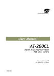
1
User's Manual
ServoCenter 3.1 Chip
User's Manual
&
Programming Guide
Yost Engineering, Inc.
630 Second Street
Portsmouth, Ohio 45662
www.YostEngineering.com
©2002-2005 Yost Engineering, Inc.
Printed in USA
1
User's Manual
Table of Contents
1 Introduction.................................................................................................................. 3
2 Features ........................................................................................................................ 3
3 Chip Overview.............................................................................................................. 4
3.1 Chip Package Diagrams...............................................................................................................4
3.1.1 PLCC.............................................................................................................................4
3.1.2 DIP................................................................................................................................ 4
3.1.3 TQFP............................................................................................................................. 5
3.2 Pin Descriptions............................................................................................................................5
4 Specifications................................................................................................................ 7
4.1 Physical..........................................................................................................................................7
4.1.1 PLCC:............................................................................................................................7
4.1.2 PDIP:............................................................................................................................. 8
4.1.3 TQFP:............................................................................................................................9
4.2 Electrical......................................................................................................................................10
4.2.1 Absolute Maximum Ratings*..................................................................................... 10
4.2.2 DC Characteristics...................................................................................................... 10
5 ServoCenter 3.1 Chip Example Support Circuitry.................................................11
5.1 Power Supply.............................................................................................................................. 11
5.2 Reset Circuit............................................................................................................................... 12
5.3 Serial Communications..............................................................................................................13
5.3.1 RS-232 Serial Communications..................................................................................13
5.3.2 TTL Serial Communications.......................................................................................14
5.4 Powering The Servos..................................................................................................................15
5.4 Connecting The Servos.............................................................................................................. 16
5.5 Clock Signals...............................................................................................................................17
5.5.1 Using a Crystal as a Clock Source.............................................................................. 17
5.5.1 Using an Oscillator as a Clock Source........................................................................ 18
5.6 Setting the Board ID.................................................................................................................. 19
5.7 Setting the Baud Rate................................................................................................................ 20
6 Programming the ServoCenter 3.1 Chip................................................................. 21
6.1 ServoCenter 3.1 Protocol........................................................................................................... 21
6.1.1 Protocol Overview...................................................................................................... 21
6.1.2 Packet Overview......................................................................................................... 22
6.1.3 Start of Packet Byte.....................................................................................................22
6.1.4 Command Set ............................................................................................................. 23
Command Summary........................................................................................................ 23
Command Details............................................................................................................ 24
6.1.5 The Checksum Value.................................................................................................. 31
7 ServoCenter 3.1 Chip Sample Schematic.................................................................32
2
User's Manual
1 Introduction
The ServoCenter Chip is a microcontroller that allows any serial communications-capable device to
control standard hobby servo motors. The chip provides easy control of the seek position and seek
speed of each of up to sixteen connected servos independently and simultaneously. This independent
control scheme allows one servo to be moving to a position slowly, while another is moving to a
different position quickly, while yet another is moving to another position at a medium speed.
The ServoCenter Chip also offers advanced control features such as absolute & relative control
command sets, raw & scaled positional modes, a simple yet reliable command protocol, and on-board
settings storage.
The ability to independently control both position and speed, combined with the controller’s flexible
and extensible feature set make the ServoCenter Chip especially useful for servo control applications
such as robotics, animatronics, motion control, automation, retail displays, and other areas where
independent or coordinated fluid servo motion is necessary or desirable.
Up to 16 motors can be connected to each ServoCenter Chip, and with proper support circuitry, up to
16 ServoCenter Chips can be “daisy-chained” together, thus allowing for a total of 256 RC servos to be
controlled independently and simultaneously from one serial device.
2 Features
•
Standard RS-232 or TTL serial control at 9600,14400,19200, or 38400 bps.
•
Control position and speed of all connected servos simultaneously.
•
Scaled motion commands allow maximum, minimum, and startup position-setting, making
complex motion programming easier.
•
Absolute and relative position commands allow for greater programming flexibility.
•
Configuration information saved even when the power is off.
•
Control up to 16 RC servos per chip.
•
Daisy-chain up to 16 chips to control up to 256 servos from one serial controller.
•
Simple yet robust serial protocol makes programming simple.
•
Downloadable example code can get you started quickly.
•
Example programs available for VC6, VB6, QBASIC, Turbo C, and GCC/LINUX.
3
User's Manual
3 Chip Overview
3.1 Chip Package Diagrams
3.1.1 PLCC
3.1.2 DIP
3.1.3 TQFP
4
User's Manual
3.2 Pin Descriptions
All of the Servo Control and Configuration pins are internally tied high through 20-50K pull-up
resistors. The /RESET pin is internally tied high through a 30-60K pull-up resistor. When used in the
charts below, logic levels 1 and 0 correspond to VDD and VSS, respectively.
•
SPA0-7 : These pins should be connected to the signal pin of servos 0-7.
•
SPB0-7 : These pins should be connected to the signal pin of servos 8-15.
•
/RESET : This pin will reset the ServoCenter Chip when it is pulled low. Use of a reset
circuit will prevent unwanted chip-resetting during power source fluctuation, but such a
circuit is not necessary for the operation of the chip.
•
RXD & TXD: The RXD and TXD pins can be used for serial communication between
the ServoCenter Chip and another device. This communication should follow the
ServoCenter Protocol.
•
VDD : VDD should be connected to a voltage in the range 2.7V-5.5V. +5V is the nominal
voltage.
•
VSS : VSS should be connected to the circuit's ground path.
5
User's Manual
•
BOARDID0-BOARDID3 : These 4 pins determine the Chip ID. See the chart below:
BOARDID0
1
0
1
0
1
0
1
0
1
0
1
0
1
0
1
0
•
BOARDID1
1
1
0
0
1
1
0
0
1
1
0
0
1
1
0
0
BOARDID2
1
1
1
1
0
0
0
0
1
1
1
1
0
0
0
0
BOARDID3
1
1
1
1
1
1
1
1
0
0
0
0
0
0
0
0
Chip ID
0
1
2
3
4
5
6
7
8
9
10
11
12
13
14
15
RATESELECT0-RATESELECT1 : These two pins determine the Data Rate for serial
communication. See the chart below:
RATESELECT0
1
0
1
0
RATESELECT1
1
1
0
0
Data Rate
9600 bps
14400 bps
19200 bps
38400 bps
•
/WPROT : This is the Write-Protection Pin. To enable Write Protection, tie WPROT to
VSS.
•
XTAL1-XTAL2 : For the ServoCenter 3.1 Chip to operate correctly, it must be
interfaced to an 8 MHz clock signal. This can be accomplished by either attaching an
oscillator to XTAL1 and leaving XTAL2 hanging, or by tying a crystal between XTAL1
and XTAL2.
6
User's Manual
4 Specifications
4.1 Physical
4.1.1 PLCC:
7
User's Manual
4.1.2 PDIP:
8
User's Manual
4.1.3 TQFP:
9
User's Manual
4.2 Electrical
4.2.1 Absolute Maximum Ratings*
Operating Temperature
Storage Temperature
Voltage on any pin except /RESET with
respect to Ground
Voltage on /RESET with respect to
Ground
Maximum Operating Voltage
DC Current per I/O pin
DC Current VDD and GND pins
-55˚C to +125˚C
-65˚C to +150˚C
-0.5V to VDD +0.5V
-0.5V to +13.0V
6.0V
40.0 mA
200.0 mA
*Notice: Stresses beyond those listed under “Absolute Maximum Ratings” may cause
permanent damage to the ServoCenter Chip. This is a stress rating only and functional
operation of the chip at these or other conditions beyond those indicated here is not implied.
Exposure to absolute maximum rating conditions for extended periods may affect device
reliability.
4.2.2 DC Characteristics
TA = -40˚C to 85˚C, VDD = 2.7V to 5.5V (Unless Otherwise Noted)
Symbol
VDD
VIL
VIH
VIH1
VOL
VOH
IIL
IIH
RRST
RPU
IDD
Parameter
Supply Voltage
Input Low
Voltage
Input High
Voltage
Input High
Voltage
Condition
Min
2.7
Max
5.5
Units
V
-0.5
0.2 VDD(1)
V
Except /RESET Pin
0.6 VDD (2)
VDD+ 0.5
V
/RESET Pin
0.9 VDD (2)
VDD + 0.5
V
Output Low
Voltage
IOL = 20mA,VDD = 5V
IOL = 10mA,VDD = 3V
Output High
Voltage
IOH = -20mA,VDD = 5V
IOL = -10mA,VDD = 3V
Input Leakage
Current
Input Leakage
Current
Reset Pull-up
Resistor
I/O Pin Pull-up
Resistor
Power Supply
Current
VDD = 5.5V, pin low
(absolute value)
VDD = 5.5V, pin high
(absolute value)
VDD = 5V
0.7
V
0.5
4.2
V
2.2
1
µA
1
µA
30
60
kΩ
20
50
kΩ
12
mA
Notes: 1. “Max” means the highest value where the pin is guaranteed to be read as low.
2. “Min” means the lowest value where the pin is guaranteed to be read as high.
10
User's Manual
5 ServoCenter 3.1 Chip Example Support Circuitry
5.1 Power Supply
Chip VDD should be in the range 2.7-5.5V.
One way to achieve this voltage is through the use of a voltage regulator such as the LP2931CZ-5.0.
EXTPWR should be at least 5V, and not greater than the maximum rating of the voltage regulator
(30V for the LP2931CZ-5.0).
Power Supply Pins
Package
VDD Pin
VSS Pin
PDIP
40
20
TQFP
38
16
PLCC
44
22
11
User's Manual
5.2 Reset Circuit
The ServoCenter Chip has an active-low /RESET input pin. Pulling this /RESET pin low will cause
the ServoCenter Chip to reset.
/RESET Pin
Package
/RESET Pin
PDIP
9
TQFP
4
PLCC
10
12
User's Manual
5.3 Serial Communications
The ServoCenter Chip has an onboard UART, which makes it very easy to implement serial
communication. The example circuits below are for RS-232 and TTL level communication.
5.3.1 RS-232 Serial Communications
The ServoCenter Chip can communicate with RS-232 capable devices via a level shifter and
appropriate support circuitry. The MAX232 in the example circuit shifts the 12V RS-232 logic signals
down to the 5V logic signals used by the ServoCenter Chip, and shifts ServoCenter Chip logic signals
up to RS-232 logic signals. For more information about the MAX232, consult its data sheet.
Serial Communication Pins
Package
TXD Pin
RXD Pin
PDIP
11
10
TQFP
7
5
PLCC
11
13
13
User's Manual
5.3.2 TTL Serial Communications
The ServoCenter Chip can communicate with serial controller devices at TTL signal levels. This can
be accomplished by simply connecting the RXD and TXD pins of the ServoCenter chip to the TX and
RX pins of the controlling device. Multiple ServoCenter Chips can receive commands from the same
controller device by simply chaining the TX and RX lines together, as shown here.
Serial Communication Pins
Package
TXD Pin
RXD Pin
PDIP
11
10
TQFP
7
5
PLCC
11
13
14
User's Manual
5.4 Powering The Servos
In addition to providing power to the ServoCenter Chip itself, the servos being controlled need must be
powered. The servos can be powered by a battery or ant other regulated power source of sufficient
amperage capability.
Servos will exhibit higher speed and torque at higher voltages. Most servos will list the operating
characteristics at 4.8V and 6V in their documentation.
The LM1084IT-ADJ is an example of an adjustable voltage regulator that can be used to accommodate
a variety of voltage requirements.
Note that a voltage regulator is not necessary if batteries or a regulated power supply is being used.
In the LM1084IT circuit shown, R1 should be around 100Ω to maintain an appropriate amount of
feedback current. The resistance of R2 should be changed to modify the output voltage of the
regulator. The Servo Supply Voltage of the LM1084IT-ADJ can be determined by using the formula:
VSERVO = 1.25 * (1 + (R2 / R1))
R2
VServo
360Ω
4.8V
470Ω
6V
15
User's Manual
5.4 Connecting The Servos
Servo Ports A & B provide the control signals for up to 16 servos. If using separate power supplies for
VSERVO and VDD, remember to tie the grounds together.
Servo Control Pins
Package
SPA Pins
SPB Pins
PDIP
32-39
1-8
TQFP
30-37
40-44, 1-3
PLCC
36-43
2-9
16
User's Manual
5.5 Clock Signals
The ServoCenter 3.1 Chip requires an 8 MHz clock signal for timing purposes. The two circuits below
are examples of how to generate this clock signal.
5.5.1 Using a Crystal as a Clock Source
In the following example, an 8 MHz crystal is used as a clock source for the ServoCenter Chip.
Clock Input Pins
Package
XTAL1 Pin
XTAL2 Pin
PDIP
19
18
TQFP
15
14
PLCC
21
20
17
User's Manual
5.5.1 Using an Oscillator as a Clock Source
In the following example, an 8 MHz oscillator is used as the clock source for the ServoCenter Chip.
Clock Input Pins
Package
XTAL1 Pin
XTAL2 Pin
PDIP
19
18
TQFP
15
14
PLCC
21
20
18
User's Manual
5.6 Setting the Board ID
The following circuit shows how to interface a DIP switch to the BOARDID (ID = BOARDID) pins.
The use of a DIP switch allows the BOARDID to be easily configured (See Section 2.2 for more
information).
Board ID Pins
Package
BOARDID0-BOARDID1 Pins
PDIP
21-24
TQFP
18-21
PLCC
24-27
19
User's Manual
5.7 Setting the Baud Rate
The above circuit shows how to interface a DIP switch to the RATESELECT (DR = RATESELECT)
pins. The use of a DIP switch allows the data rate to be easily configured (See Section 2.2 for more
information).
Rate Select Pins
Package
RATESELECT0 Pin
RATESELECT1 Pin
PDIP
26
25
TQFP
23
22
PLCC
29
28
20
User's Manual
6 Programming the ServoCenter 3.1 Chip
6.1 ServoCenter 3.1 Protocol
6.1.1 Protocol Overview
The ServoCenter 3.1 controller receives messages from the controlling system in the form of
sequences of serial communication bytes called packets. Each byte is serial encoded using 8N1 serial
encoding ( 8 data bits, no parity, and 1 stop bit). The packet size can range from three to six bytes in
length, depending upon the nature of the command being sent to the controller. Each packet consists
of an initial “start of packet” byte (which includes a board ID specifier), followed by a “command
value” specifier byte, followed by zero to three “command data” bytes, and terminated by a packet
“checksum value” byte.
The ServoCenter 3.1 controller buffers the incoming command stream and will only take an action
once the entire packet has been received and the checksum has been verified as correct. Incomplete
packets, packets with inappropriate chip IDs, and packets with incorrect checksums will be ignored.
This allows the controlling system to send command data at leisure without loss of function. The
command buffer will, however, be cleared whenever the ServoCenter controller is either reset or
powered off/on.
Most ServoCenter commands return no result data. Certain commands, however, are designed to
return status information about the current settings and positions of connected servos. It is important
to note that although many ServoCenter 3.1 chips can be connected and controlled simultaneously by a
single controller, only one of the connected boards may be configured to send data back to the
controlling system. The transmit/receive functionality is determined by the Chip Communications
Circuit.
21
User's Manual
6.1.2 Packet Overview
Each packet is from 3 to 6 bytes in length and is formatted as follows:
240(0xF0) + Chip ID
First Byte – Start of Packet. Calculated by adding
240 to the desired chip ID.
Second Byte – Command Value. Selected from
one of the possible control commands.
Command ID
}
Command Data
Command Data/ Command Parameters.
Varies from zero to three bytes depending upon the
command specified in the second byte position. See
the table below for specific command data format
and specification.
Command Data
Command Data
Checksum Value
Last Byte – Packet Checksum. See the checksum
description below for specific calculation information.
Typical ServoCenter 3.1 Command Packet
6.1.3 Start of Packet Byte
Each command packet starts with a specific type of byte called the “Start of Packet” byte. The “Start
of Packet” byte serves two purposes: to signify the start of a command packet and to identify the chip
ID of the intended recipient. This byte's value is calculated by adding 240 ( 0xf0 hex ) to the chip ID
of the chip to which you are sending the command message. Thus a byte value of 240(0xf0 hex)
would be used to send a message to the chip with ID 0, 241(0xf1) for chip ID 1, 242(0xf2) for chip ID
2, etc.
22
User's Manual
6.1.4 Command Set
Command Summary
The table below summarizes the ServoCenter 3.1 command set.
Description
Command Data Length Data Descriptions
QuickMove
0 (x00)
2
SvNum(0~15), SvPosition(0~200)
Scaled QuickMove
1 (0x01)
2
SvNum(0~15), %SvPosition(0~100%)
Servo Enable
2 (0x02)
1
SvNum(0~15)
Servo Disable
3 (0x03)
1
SvNum(0~15)
Set Min
4 (0x04)
2
SvNum(0~15), SvPosition(0~200)
Set Max
5 (0x05)
2
SvNum(0~15), SvPosition(0~200)
Set Start
6 (0x06)
2
SvNum(0~15), SvPosition(0~200)
Set Max Speed
7 (0x07)
2
SvNum(0~15), SvMaxSpeed(1~200) in centi-secs / 60°
Set Min to Current
8 (0x08)
1
SvNum(0~15)
Set Max to Current
9 (0x09)
1
SvNum(0~15)
Set Start To Current
10 (0x0a)
1
SvNum(0~15)
Get Current Position
11 (0x0b)
1
SvNum(0~15)
Get Min Position
12 (0x0c)
1
SvNum(0~15)
Get Max Position
13 (0x0d)
1
SvNum(0~15)
Get Start Position
14 (0x0e)
1
SvNum(0~15)
Get Max Speed
15 (0x0f)
1
SvNum(0~15)
Move Raw
16 (0x10)
3
SvNum(0~15), SvPosition(0~200), SvSpeed(1~100)
Move Raw CW
17 (0x11)
3
SvNum(0~15), ∆SvPosition(0~200), SvSpeed(1~100)
Move Raw CCW
18 (0x12)
3
SvNum(0~15), ∆SvPosition(0~200), SvSpeed(1~100)
Move Scaled
19 (0x13)
3
SvNum(0~15), %SvPosition(0~100), SvSpeed(1~100)
Move Scaled CW
20 (0x14)
3
SvNum(0~15), ∆%SvPosition(0~100), SvSpeed(1~100)
Move Scaled CCW
21 (0x15)
3
SvNum(0~15), ∆%SvPosition(0~100), SvSpeed(1~100)
Set Pulse Width Min
22 (0x16)
1
PwValue(1 – 239) in 10us units.
Set Pulse Width Max
23 (0x17)
1
PwValue(1 – 239) in 10us units.
Servo Reverse
24 (0x18)
1
SvNum(0~15)
Servo Normal
25 (0x19)
1
SvNum(0~15)
Show Settings
235 (0xeb)
0
None.
Commit Settings
236 (0xec)
0
None.
Load Factory Settings
237 (0xed)
0
None.
Reset as Startup
238 (0xee)
0
None.
Display Version
239 (0xef)
0
None.
23
User's Manual
Command Details
In the tables below you'll find a description of each of the ServoCenter commands and a brief
explanation of how and where each command would be used.
Function:
QuickMove
Command Value: 0 (0x00)
Data Bytes:
2
Data Format:
SvNum(0~15), SvPosition(0~200)
Description:
The QuickMove command provides a method of instantly moving a single servo (specified by SvNum)
to a specified raw position (specified by SvPosition). This function is useful when it is desired to move
a servo to a position as fast as possible. With QuickMove no servo position interpolation is performed
and the control signal for that specified servo is immediately modified when the command is issued.
Function:
Servo Enable
Command Value: 2 (0x02)
Data Bytes:
1
Data Format:
SvNum(0~15)
Description:
The Servo Enable command provides a method of enabling a servo(specified by SvNum). This
function is used to enabled a servo channel that has been previously disabled. With the control signal
enabled the servo will actively hold its position. Enabled servos will draw significantly more power
than disabled servos.
Function:
Servo Disable
Command Value: 3 (0x03)
Data Bytes:
1
Data Format:
SvNum(0~15)
Description:
The Servo Disable command provides a method of disabling a servo(specified by SvNum). This
function is used to remove the control signal for a servo channel. With the control signal disabled the
servo will not actively hold its position. This can be useful for disabling a servo without having to
physically disconnect it from the chip. A disabled servo can generally be moved by hand and will draw
significantly less power than an enabled servo.
Function:
Set Minimum
Command Value: 4 (0x04)
Data Bytes:
2
Data Format:
SvNum(0~15), SvPosition(0~200)
Description:
The Set Minimum command sets the minimum raw servo position set-point(specified by SvPosition) of
the specified servo (specified by SvNum). This minimum position is used in all scaled movement
modes of operation. Setting the minimum position above the start position will cause the start position
to be set equal to the minimum. Setting the minimum position above the maximum will cause the
maximum position to be set equal to the minimum.
24
User's Manual
Function:
Set Maximum
Command Value: 5 (0x05)
Data Bytes:
2
Data Format:
SvNum(0~15), SvPosition(0~200)
Description:
The Set Maximum command sets the maximum raw servo position set-point(specified by SvPosition)
of the specified servo (specified by SvNum). This maximum position is used in all scaled movement
modes of operation. Setting the maximum position below the start position will cause the start position
to be set equal to the maximum. Setting the maximum position below the minimum will cause the
minimum position to be set equal to the maximum.
Function:
Set Start
Command Value: 6 (0x06)
Data Bytes:
2
Data Format:
SvNum(0~15), SvPosition(0~200)
Description:
The Set Start command sets the starting raw servo position set-point(specified by SvPosition) of the
specified servo (specified by SvNum). The start position is the position that the servo will assume
when the system is powered-up or reset. The start position is capped and cannot be set greater than the
max or less than the min.
Function:
Set Maximum Speed
Command Value: 7 (0x07)
Data Bytes:
2
Data Format:
SvNum(0~15), SvMaxSpeed(1~200)
Description:
The Set Maximum Speed command sets the maximum speed ( as specified by SvMaxSpeed and
measured in centi-seconds per 60° of travel) that is allowed for a particular servo channel (specified by
SvNum). This maximum speed is used to calculate all speed related seek commands. Different servos
have different rated travel speeds depending upon the manufacturer, model, and power supply voltage.
These speeds are generally rated in seconds per 60° of travel so the programmer will have to convert
the rated speed ( in seconds) to centi-seconds by multiplying by 100. The ServoCenter 3.1 controller
allows the maximum allowable travel speed to be set independently for each of the 16 servo channels.
Function:
Set Minimum to Current
Command Value: 8 (0x08)
Data Bytes:
1
Data Format:
SvNum(0~15)
Description:
The Set Minimum to Current command sets the minimum raw servo position set-point to the current
raw position of the servo of the specified servo (specified by SvNum). This minimum position is used
in all scaled movement modes of operation. Setting the minimum position above the start position will
cause the start position to be set equal to the minimum. Setting the minimum position above the
maximum will cause the maximum position to be set equal to the minimum.
25
User's Manual
Function:
Set Maximum to Current
Command Value: 9 (0x09)
Data Bytes:
1
Data Format:
SvNum(0~15)
Description:
The Set Maximum to Current command sets the maximum raw servo position set-point to the current
raw position of the specified servo (specified by SvNum). This maximum position is used in all scaled
movement modes of operation. Setting the maximum position below the start position will cause the
start position to be set equal to the maximum. Setting the maximum position below the minimum will
cause the minimum position to be set equal to the maximum.
Function:
Set Start to Current
Command Value: 10 (0x0a)
Data Bytes:
1
Data Format:
SvNum(0~15)
Description:
The Set Start to Current command sets the startup raw servo position set-point to the current raw
position of the specified servo (specified by SvNum). The start position is the position that the servo
will assume when the system is powered-up or reset. The start position is capped and cannot be set
greater than the maximum or less than the minimum.
Function:
Get Current Position
Command Value: 11 (0x0b)
Data Bytes:
1
Data Format:
SvNum(0~15)
Description:
The Get Current Position command causes the ServoCenter board to transmit a one byte message
corresponding to the raw servo position of a particular servo (specified by SvNum). The ability of the
board to send these responses is partially dependent upon the jumper settings of jumper block JP1 ( see
section 3.4.1 of the user's manual for details ).
Function:
Get Min Position
Command Value: 12 (0x0c)
Data Bytes:
1
Data Format:
SvNum(0~15)
Description:
The Get Min Position command causes the ServoCenter board to transmit a one byte message
corresponding to the currently set minimum servo position of a particular servo (specified by SvNum).
The ability of the chip to send these responses is partially dependent upon the wiring of the
communications circuitry.
26
User's Manual
Function:
Get Max Position
Command Value: 13 (0x0d)
Data Bytes:
1
Data Format:
SvNum(0~15)
Description:
The Get Max Position command causes the ServoCenter board to transmit a one byte message
corresponding to the currently set maximum servo position of a particular servo (specified by SvNum).
The ability of the chip to send these responses is partially dependent upon the wiring of the
communications circuitry
Function:
Get Start Position
Command Value: 14 (0x0e)
Data Bytes:
1
Data Format:
SvNum(0~15)
Description:
The Get Start Position command causes the ServoCenter board to transmit a one byte message
corresponding to the currently set starting servo position of a particular servo (specified by SvNum).
The ability of the chip to send these responses is partially dependent upon the wiring of the
communications circuitry
Function:
Get Max Speed
Command Value: 15 (0x0f)
Data Bytes:
1
Data Format:
SvNum(0~15)
Description:
The Get Max Speed command causes the ServoCenter board to transmit a one byte message
corresponding to the currently set maximum speed setting of a particular servo channel (specified by
SvNum). The ability of the chip to send these responses is partially dependent upon the wiring of the
communications circuitry
Function:
Move Raw
Command Value: 16 (0x10)
Data Bytes:
3
Data Format:
SvNum(0~15), SvPosition(0~200), SvSpeed(1~100)
Description:
The Move Raw command is used to move a servo's position at a specified speed. The move raw
command moves a servo ( specified by SvNum ) to a raw position ( specified by SvPosition ) at a
particular speed ( specified by SvSpeed ). Raw movement modes do not use the set minimum and
maximum points to determine the servo's position. The specified speed is calculated as a percentage of
the preset maximum servo speed for the specified servo channel. Thus, a speed of 50 is half as fast as
a speed of 100, a speed of 1 is 1/100th as fast as a speed of 100, etc.
27
User's Manual
Function:
Move Raw CW ( Clockwise )
Command Value: 17 (0x11)
Data Bytes:
3
Data Format:
SvNum(0~15), ΔSvPosition(0~200), SvSpeed(1~100)
Description:
The Move Raw CW command is used to move a servo's position clockwise by a certain amount at a
specified speed. The move raw clockwise command moves a servo ( specified by SvNum ) clockwise
by a certain number of units ( specified by ΔSvPosition ) at a particular speed ( specified by SvSpeed ).
Function:
Move Raw CCW ( Counter-Clockwise )
Command Value: 18 (0x12)
Data Bytes:
3
Data Format:
SvNum(0~15), ΔSvPosition(0~200), SvSpeed(1~100)
Description:
The Move Raw CCW command is used to move a servo's position counter-clockwise by a certain
amount at a specified speed. The move raw counter-clockwise command moves a servo ( specified by
SvNum ) clockwise by a certain number of units ( specified by ΔSvPosition ) at a particular speed
( specified by SvSpeed ).
Function:
Move Scaled
Command Value: 19 (0x13)
Data Bytes:
3
Data Format:
SvNum(0~15), %SvPosition(0~100), SvSpeed(1~100)
Description:
The Move Scaled command is used to move a servo's position at a specified speed. The move scaled
command moves a servo ( specified by SvNum ) to a scaled position ( specified by SvPosition ) at a
particular speed ( specified by SvSpeed ). Scaled movement modes use the set minimum and
maximum points to determine the servo's position. The scaled position value can be thought of as a
percentage of the range from the minimum to the maximum. Thus 0 is the minimum, 100 is the
maximum, and 50 is the midpoint between the set minimum and maximum. The specified speed is
calculated as a percentage of the preset maximum servo speed for the specified servo channel. Thus, a
speed of 50 is half as fast as a speed of 100, a speed of 1 is 1/100th as fast as a speed of 100, etc.
Function:
Move Scaled CW ( Clockwise )
Command Value: 20 (0x14)
Data Bytes:
3
Data Format:
SvNum(0~15), Δ%SvPosition(0~100), SvSpeed(1~100)
Description:
The Move Scaled CW command is used to move a servo's position clockwise at a specified speed.
The move scaled clockwise command moves a servo ( specified by SvNum ) clockwise by a certain
percentage ( specified by Δ%SvPosition ) at a particular speed ( specified by SvSpeed ). The
percentage indicated by the %SvPosition byte is based upon a percentage of the distance between the
minimum position and the maximum position. Thus a distance of 10 units would move the servo
clockwise by a distance of 1/10th of the entire scaled travel range, a distance of 1 unit would move the
servo by 1/100th of the entire scaled travel range, etc.
28
User's Manual
Function:
Move Scaled CCW ( Counter-Clockwise )
Command Value: 21 (0x15)
Data Bytes:
3
Data Format:
SvNum(0~15), Δ%SvPosition(0~100), SvSpeed(1~100)
Description:
The Move Scaled CCW command is used to move a servo's position counter-clockwise at a specified
speed. The move scaled counter-clockwise command moves a servo ( specified by SvNum ) counterclockwise by a certain percentage ( specified by Δ%SvPosition ) at a particular speed ( specified by
SvSpeed ). The percentage indicated by the %SvPosition byte is based upon a percentage of the
distance between the minimum position and the maximum position. Thus a distance of 10 units would
move the servo clockwise by a distance of 1/10th of the entire scaled travel range, a distance of 1 unit
would move the servo by 1/100th of the entire scaled travel range, etc.
Function:
Set Pulse Width Min
Command Value: 22 (0x16)
Data Bytes:
1
Data Format:
PwValue (1-239)
Description:
The Set Pulse Width Minimum command lets the user specify the minimum value of the range of
control pulses that are produced by the ServoCenter 3.1 chip for all raw position modes. This
minimum value is applied globally to all servo channels of the chip. Since some servos have slightly
different control pulse width ranges this value may have to be tweaked to get a full servo motion range
out of all raw position modes. The PwValue is measured in 10 microsecond units thus allowing the
chip to produce any range of pulses in the range from 10 to 2390 microseconds.
Function:
Set Pulse Width Max
Command Value: 23 (0x17)
Data Bytes:
1
Data Format:
PwValue (1-239)
Description:
The Set Pulse Width Maximum command lets the user specify the maximum value of the range of
control pulses that are produced by the ServoCenter 3.1 chip for all raw position modes. This
maximum value is applied globally to all servo channels of the chip. Since some servos have slightly
different control pulse width ranges this value may have to be tweaked to get a full servo motion range
out of all raw position modes. The PwValue is measured in 10 microsecond units thus allowing the
chip to produce any range of pulses in the range from 10 to 2390 microseconds.
Function:
Servo Invert
Command Value: 24 (0x18)
Data Bytes:
1
Data Format:
SvNum(0~15)
Description:
The Servo Invert command causes the servo channel specified by the first data byte (SvNum) to have
its positions seek in an inverted manner. This means that a raw position value of zero is the servo's
extreme counter-clockwise rotational position and 200 is the extreme clockwise position. This
function can be useful for dealing with paired servos or with servos that are mounted in such a way that
an inverted positional system is more natural.
29
User's Manual
Function:
Servo Normal ( UnInvert )
Command Value: 25 (0x19)
Data Bytes:
1
Data Format:
SvNum(0~15)
Description:
The Servo Normal command causes the servo channel specified by the first data byte (SvNum) to have
its positions seek in the normal, non-inverted, manner. This means that a raw position value of zero
is the servo's extreme clockwise rotational position and 200 is the extreme counter-clockwise position.
Function:
Show Settings
Command Value: 235 (0xeb)
Data Bytes:
0
Data Format:
None.
Description:
The Show Settings command causes the chip to transmit a table of the current settings for all channels.
The format of the returned data is a human-readable table composed of ASCII characters. This fuction
is useful when troubleshooting a chip's settings or simply verifying current settings. The ability of the
chip to transmit these settings is partially dependent upon the wiring of the communications circuitry
Function:
Commit Settings
Command Value: 236 (0xec)
Data Bytes:
0
Data Format:
None.
Description:
The Commit Settings command causes the chip to save the current settings into the EEPROM storage.
Once the board's settings are stored in the EEPROM settings of the ServoCenter 3.1 they will be
restored every time the chip is either reset or powered up. This allows the configuration to be saved
thus avoiding a configuration process every time the chip is reset. Note: the EEPROM storage of the
ServoCenter 3.1 chip has a limited lifetime of rewritability (about 100,000 rewrites) so avoid writing a
programmatic loop that continuously commits the settings of the chip. The current rewrite count can
be viewed by using the “Show Settings” command. A user can prevent chip settings from being written
by connecting the WProt pin to GND.
Function:
Load Factory Settings
Command Value: 237 (0xed)
Data Bytes:
0
Data Format:
None.
Description:
The Load Factory Settings command causes all of the chip's settings to revert to the state that they
were in when shipped as new. This command only loads the settings and doesn't commit the settings to
the EEPROM of the chip. To restore the settings and save these settings, the user should perform a
“Commit Settings” command following the “Load Factory Settings” command.
30
User's Manual
Function:
Reset as Startup
Command Value: 238 (0xee)
Data Bytes:
0
Data Format:
None.
Description:
The Reset as Startup command causes the chip to perform a software reset of the control software.
This command is functionally equivalent to resetting or cycling the power of the chip. All EEPROM
settings are loaded and all servo channels are modified according to these stored settings.
Function:
Display Version
Command Value: 239 (0xef)
Data Bytes:
0
Data Format:
None.
Description:
The Display Version command simply displays the version of the firmware embedded within your
ServoCenter 3.1 chip. This can be useful for allowing software to query the chip's version to ensure
interoperability between this and other/future YEI products.
6.1.5 The Checksum Value
The checksum is computed as an arithmetic summation of all of the characters in the packet ( except
the checksum value itself) modulus 239 plus one. This gives a resulting checksum in the range 1 to
239. The checksum will be ignored if a 0 byte value is passed in the checksum position of the packet.
The purpose of the checksum is to minimize the chances of the ServoCenter 3.1 chip receiving and
acting upon corrupted or erroneous control messages. In most instances the checksum should be used
to enhance the reliability and robustness of the control system, but, as noted above, a zero value can be
placed in the checksum byte position to ignore the checksum calculation.
This placing of a 0 value in the checksum position can free the sender from having to worry about
calculating the actual checksum. This is useful in situations where simplicity of implementation is
necessary and reliable communication is not a requirement.
31
User's Manual
7 ServoCenter 3.1 Chip Sample Schematic
Note: The pin numbers used in this schematic correspond to those of the PLCC package.
32