1
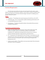
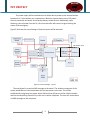
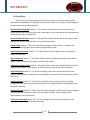
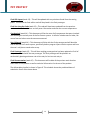
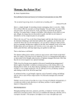
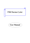
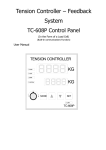
PET PROTECT Problem Statement Every year, thousands of dogs attend dog shows around the country. These dogs can cost anywhere from $500 to $10,000, with an additional cost of nearly $5000/year for general maintenance. During dog shows, most dogs are kept in recreational vehicles (RV’s) that are under minimal supervision. The temperature inside the RV’s can reach dangerous levels in a short amount of time, which can be life threatening to the dog. If a dog dies, the owner will lose a companion as well as any financial gain that could be made from the dog in the future. If the dog dies while in the possession of a handler, that person will lose all credibility as a proper caretaker and might not ever have a job in the business again. The main problem that faces owners when leaving their dogs unattended is the constant threat of extreme temperatures within the RV. Another occurrence is when there is a loss of shore power, i.e., the loss of power provided by the nearest building, or a malfunctioning generator on the RV itself. Moreover, the last may cause several problems such as carbon monoxide and smoke. The owner has no way of knowing what is happening to their dog inside the RV and must rely on the good nature of the fellow participants at the show. However, there may not always be someone around to alert of dangers, or the dangers may not be apparent from the outside. Bonnie Engineering will design a system that will solve these problems. The Pet Protect system will be able to detect temperature, carbon monoxide, power loss, and smoke. Whenever one of these variables is found to be out of the desired range, a text message will be sent to the owner’s cell phone to alert them of this problem. Additionally, a speech alarm will sound from inside the RV alerting anyone in the proximity that a dog is in danger and requires assistance. The owner will be able to program the upper and lower bounds of temperature tolerance inside the RV as well as provide a cell phone number for the system to store and notify if needed. The temperature will be displayed constantly on the LCD screen of the system. This system will be able to prevent dogs from any harm and will leave their owners in a more peaceful state of mind. 1 PET PROTECT Functional Requirements The Pet Protect system will consist of one main unit that will contain sensors, power detection, and wireless communication capability. An alarm will be an external component that will correspond with the microprocessor whenever danger is detected. The following sets of elements makeup this system: Sensors: Temperature – This will detect the internal temperature of the RV from -40 to 125˚C. Carbon Monoxide – This is a sensitive device capable of detecting small amounts of CO at around 400 PPM (parts per million). Smoke detector – This device will be able to detect smoke particles like any common household smoke detector. Overall System’s Input/Output Devices: Keypad - This will provide input to the system. The user will be able to enter data through the keypad in order to save the phone number to be notified when emergencies occur. Additionally, the keypad will also allow the user to enter the maximum tolerable temperature setting inside the recreational vehicle. LCD - The purpose for the implementation of the LCD screen is to provide the user with information such as the current temperature in the RV. Evidently, the LCD will display a prompt to the user for entering data. Inputs entered through the keypad will be displayed on the LCD. Cellular connection device – This provides a one-way communication link to the owner’s cell phone in case of an emergency. 2 PET PROTECT Conceptual Design The scope of our design is to implement a system that will be able to periodically monitor the internal environmental conditions of a recreational vehicle (RV). Our system will be mounted inside the RV and will consist of sensors that constantly take measurements of the environment. It will also include an LCD screen and keypad to assist the owner in monitoring their RV. Finally, the Pet Protect system will have an internal SIM card module that will be able to connect to the cellular network and alert the owner via text message of any danger detected by the system inside the RV. To further aid in warning of danger, the system will have a speech type alarm that will help get the attention of any person passing by the vehicle. Figure 1 illustrates our system. Figure 1: Conceptual Design The system implemented will be able to detect changes in temperature, carbon monoxide at about 1000 ppm (particles per million), detect smoke at around 600 ppm, and detect power loss from its current source, at which point the system will switch to the internal battery. When any abnormal conditions are detected, the system will automatically send a text message to the owner’s cell phone through the cellular network to alert of the dangers and allow the owner to take immediate action to prevent the loss of valuable pets. Moreover, the 3 PET PROTECT audible alarm will sound in order to get the attention of any person in the proximity of the vehicle. The alarm will not be a buzzing noise or anything that is similar to a car alarm. On the contrary, the alarm will be a prerecorded voice that would sound “Emergency” or “Danger” thus further gaining the attention of any individual since many people today are used to the common buzzing alarms that they tend to ignore them. Due to the animal’s sensitive response to extreme temperatures, it is deemed necessary to have a temperature tolerance bracket. For that purpose, the owner of the system will be able to program the system through the use of the keypad as an input and enter the maximum and minimum temperature allowable inside the RV. When the system detects that the temperature has reached that point, the device will alert the owner. The owner will also be able to program into the system the phone number(s) that the device will use to get in contact with the owner’s cell phone. An LCD screen will be incorporated to display the temperature inside the RV periodically so the owner can check what the temperature is before leaving the RV or at anytime. Moreover, the LCD will echo the data that is programmed into the system through the keypad. Performance Requirements Sensors: Temperature o Detect variances in area o Range from -20 to 100 °C o Response time <10sec Power Loss o Detect loss of shore power o Battery backup Carbon Monoxide o Detect in parts per million o Sensor is inside unit o Response time <10sec Smoke o Similar to over the counter model o Sensor is inside unit o Response time <10sec 4 PET PROTECT Visual Input/Output: LCD o Displays temperature constantly o Takes outputs from microcontroller o Prompts for temperature max and min as well as user phone number o Powered by 5V Keypad o 12 buttons o Used to input into microcontroller memory o Powered by 3.5 to 5V Alarming Methods: Audible Alarm o Outputs a humanistic voice that is distinguishable from a car alarm o Loud and recognizable speech stating “EMERGENCY” Wireless Communication o Sent via SIM card o Received on user’s cell phone o Transmitted through the cellular network System: Runs off of shore power(power from nearby building) Battery backup Voltage required: 3 to 5V Small system design, <25in² Located at wall plug Microcontroller o Four analog to digital converter inputs o 64K memory o 32 bit processor o At least 6 digital Inputs and Outputs Technology Survey Assessment: Sensors: Smoke: Photocell Smoke Detector o Pros - It will be able to detect small amounts of smoke by using light reflected off of the smoke. Can be located anywhere in the RV and does not have to be on the ceiling. o Cons - Is more expensive than traditional smoke detectors. 5 PET PROTECT Carbon Monoxide: CO detector o Pros - Will be very sensitive, capable of detecting up to 400 ppm of CO. Is guaranteed to last for at least 24 months. o Cons - Very sensitive device that is more expensive than all other sensor combined. Does not work above 122°F. Temperature: IC Temperature Sensor o Pros - able to detect temperature variations from -55 to 150°C. o Cons - sensor’s output is analog and will need a signal conditioning circuit and an A/D to be able to be read by microcontroller. Visual Input / Output: Keypad: Grayhill 12 button keypad o Pros - 0-9 keys as well as # and * inputs to be able to input into the system. o Cons - has no return or backspace button. Will have to program the system to recognize the # and * as these buttons. LCD: Matrix Orbital LCD 2041 o Pros - Easy to program and use for this system. o Cons - Requires a 5V regulator due to its low resiliency. Alarming methods: Audible alarm: Voice Synthesizer o Pros - Will gain the attention of a casual pedestrian in proximity to the RV, will be loud, and will be recognizably different from a car alarm. o Cons - Is more expensive than a normal whooping alarm. Wireless Communication: GSM o Pros - Is the most used cellular system in the world and is widely deployed in the continental US. o Cons - does not provide coverage everywhere, alarms will have to be saved until the signal is strong enough to send a text message. 6 PET PROTECT Functional Block Diagram: As seen in Figure 2, a temperature sensor will measure the changes that are occurring around the unit. This is done by the device’s output being a digital value. Figure 2: Functional Design – Sensors This output voltage is fed into the microcontroller to be analyzed. The microcontroller will be pre-programmed by the user to send an alert signal whenever the temperature reads higher than the value. The carbon monoxide sensor and the smoke sensor will follow the same process to be implemented. As seen in Figure 3, the manner in which the inputs will be received is from a 12-button keypad. The keypad will be used to enter data into the microcontroller’s memory. 7 PET PROTECT 5 bits Figure 3: Functional Design – Input/Output Specifically, the data that will be entered will be the owner’s cell phone number as well as the maximum tolerable temperature setting in the RV. These inputs will be echoed to the LCD screen that will be powered by a 5V regulator to prevent damages to the LCD. The LCD will prompt the user for these inputs. Additionally, the LCD will constantly display the current temperature of the RV. Figure 2 illustrates how the microprocessor receives input from the keypad and outputs to the LCD. As seen in Figure 4, the device will be powered from a standard power outlet internal to the RV. Figure 4: Functional Design - Power 8 PET PROTECT The power supply will be conditioned so it will be able to power up the internal devices between 3 to 5 Volts without any complications. When the system detects loss of AC power, the microcontroller will switch to the backup battery inside the unit. Additionally, upon detecting a loss of power from the RV, the microcontroller will transmit a signal alerting the owner of the emergency. Figure 5 illustrates the overall design of how the system will be executed. Cell Comm. Unit Figure 5: Functional Design – System The overall goal is to send an SMS message to the owner. The wireless component of the system establishes an interface between the microprocessor to the user. This will be established by integrating the system with a SIM card that will be part of the cellular network and thus accomplishing connectivity to the user’s cellular telephone. The user will receive alerts via SMS messages to the cell phone. 9 PET PROTECT Deliverables: During the course of developing the Pet Protect system, various documents will be presented to stakeholders and other groups who have interest in our project. The following are the documents that will be presented. Functional Block Diagram (week 1) – This contains information as to how the Pet Protect system will process data coming from the various signals. Key components will be addressed as well as how the data is transferred. Hierarchy and Flow Chart (week 4) – These two documents will help derive the program code and will give a visual representation as to how the code works. Pseudo Code (week 4) – This is the basis that the program code is built on. It explains the program code using English terms instead of programming code. Initial System Schematic (week 2) – This will contain the circuit diagrams for the hardware design of the product. System Parts List (week 1) – This will list all parts used to produce a prototype of the system design. It will include prices as well as technical information. Initial User Interface Code (week 4) – This code will be in the system and will allow the user to program their inputs into the system. It will be tested for ease of use and functionality. Initial PCB Layout (week 5) – This will be a working system that can be used for the initial testing of the hardware and will give the stakeholders an idea of what the final product will be like in size. Initial Prototype (week 12) – This unit will include all parts necessary to have a working prototype so that testing may be done and opinions can be gathered from stakeholders as to design/functionality. Testing of System (week 12) – Many tests will have to be done in order to correct any problems that may have occurred due to errors that may have occurred. These changes will be implemented on the final product. Final System Schematic (week 13) – This circuit diagram will have been updated with the solutions to the problems found during testing. 10 PET PROTECT Final PCB Layout (week 13) – This will be updated with any solutions found from the testing phase. This will be the final edition and will be placed in the final prototype. Final User Interface Code (week 13) – This code will have been updated from the previous version and will allow the user to easily enter information and view the current temperature. Cost Analysis (week 14) – This document will list the costs of all components that were involved with building the various parts of the Pet Protect system. It will also include costs for labor, lab access fees and other costs the team encountered. User’s Manual (week 14) – This document will ship with the final prototype and will describe how to use the Pet Protect system, specifically how to program inputs into the system and how the user’s cell phone needs to be set up. Final Prototype (week 15) – This will be a working prototype that has been updated to fix all of the problems found with the test prototype. This final prototype will be placed in an aesthetically pleasing enclosure and will be ready for final test and analysis. Final Documentation (week 15) – This document will include all the previous work that has been done on this product as well as technical information for the use of the product. The deliverables timeline is shown in Figure 6. This schedule shows the predicted dates of submission for all of the items above. 11 PET PROTECT Functional Block Diagram 26 August 2008 Initial PCB Layout 5 October 2008 Initial System Schematic 19 September 2008 Final System Schematic 11 November 2008 User’s Manual 19 November 2008 Initial Prototype 5 November 2008 Final User Interface Code Final Documentation 15 November 2008 21 November 2008 final 14 November 2008 Pseudo Code 24 September 2008 final 14 November 2008 Initial User Interface Code 26 September 2008 Hierarchy and Flow Chart 24 September 2008 Final PCB Layout 12 November 2008 final 14 November 2008 Final Prototype 21 November 2008 Testing of System 6 November 2008 final 14 November 2008 Cost Analysis 19 November 2008 System Parts List 28 August 2008 Figure 6: Deliverables Schedule 12 final 14 November 2008 final 14 November 2008 PET PROTECT Milestones: In order to assist in determining the progress of the project development, a number of milestones have been established. A milestone is considered to be a personal achievement to the team that corresponds to the completion and acceptance of an important landmark. The milestones are as follows: Completion of Research (week 1) –The research of this project encompasses the hardware and the software that will be needed to develop the Pet Protect system. The research will include finding the right sensors for the system, the software necessary to program the microcontroller, and the wireless communication interface. Acceptance of Hardware Design through Simulations (week 5) – This will include attaining the characteristics of the sensors through physical testing followed by software simulation with the collected data to analyze the signal conditioning required for proper calibration of the signal output. From this, we will be able to implement our design for the hardware. Acceptance of Software Design (week 6) – The completion of the software indicates that the microcontroller has been successfully programmed to receive inputs from all the sensors and deliver correct outputs. Acceptance of Hardware Design (week 8) – The completion of the hardware implies that the PCB layout has been established and that all the components have been implemented. This initial layout will be used for testing to ensure that our analysis was correct. Acceptance of the Input and Output Interface (week 8) – This implies, the completion of a fully functional system where the user can enter inputs through the keypad and observe output through the LCD screen. Interfacing the Hardware with the Software (week 9) – This milestone implies that the sensors are supplying the correct input to the microcontroller. The microcontroller must be able to provide the output to the LCD display and to the alarm whenever necessary. Additionally, the user should be able to save data into the system and be able to recall it. Wireless Communication (week 12) – Completion of this step demonstrates the functionality of the system to make contact to the user’s cell phone. Accomplishing this is a significant milestone. 13 PET PROTECT Completion and Approval of the Pet Protect Prototype (week 13) – A prototype of the Pet Protect system will be assembled in order to demonstrate the full functionality of the system. The system should be able to detect changes in temperature, power loss, carbon monoxide, and smoke in the environment and contact the user via text messaging on his/her cell phone. Completion of Documentation (week 14) – The last step in the process is in the delivery of documentation. Documentation for the Pet Protect system will include a schematic of the system, a user’s manual, an installation guide, and a technical report including test results. Figure 7 illustrates the tentative dates in which the milestones will be accomplished. Figure 7. Milestones 14