1
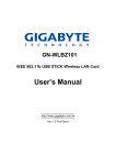
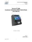
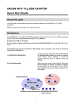
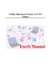
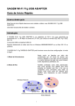
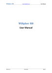
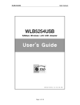
GN-WLM01
IEEE 802.11b PCMCIA Wireless LAN Card
User’s Manual
http://www.gigabyte.com.tw
Rev. 1.0 First Edition
Contents
CHAPTER 1. PRODUCT OVERVIEW ..........................................................................................1
1-1. INTRODUCTION TO THE WIRELESS LAN CARD ...............................................................1
1-2. FEATURES .................................................................................................................1
1-3. PHYSICAL DIMENSIONS/PACKAGING .............................................................................1
1-4. LED INDICATING LIGHT ...............................................................................................2
1-4-1. Purpose.............................................................................................................................2
1-4-2. Description .......................................................................................................................2
1-5. SYSTEM REQUIREMENTS ............................................................................................2
1-5-1. Supported Platform .........................................................................................................2
1-5-2. Supported Operation System........................................................................................2
CHAPTER 2. INSTALLING THE WIRELESS LAN CARD........................................................3
2-1. INSTALLING THE DRIVER & UTILITY (APPLICABLE TO ANY SUPPORTED OS) .....................3
CHAPTER 3. USING THE UTILITY...............................................................................................7
3-1.
3-2.
3-3.
3-4.
INFO .........................................................................................................................7
CONFIGURATION ........................................................................................................9
ENCRYPTION ...........................................................................................................11
ABOUT ....................................................................................................................12
CHAPTER 4. SPECIFICATIONS .................................................................................................13
Chapter 1. Product Overview
1-1. Introduction to The Wireless LAN Card
This wireless LAN (Local Area Network) card is composed of the IEEE 802.11b MAC,
Baseband, and radio components, PCMCIA interface, and two built-in antennas. This
product adopts the direct sequence spread spectrum (DSSS) technology and the DBPSK,
DQPSK, and CCK modulation mode to provide a very stable wireless communication
quality and an excellent signal receiver capability.
Our product features the compact size, low power consumption, and power management
functions, and provides a high-speed wireless data communication. Therefore, our
product is ideally suitable for being integrated into the personal mobile and handheld
platform.
Because of the nature of wireless communication, the received signal quality depends on
different environments and locations, ordinary users generally do not have much idea
where to put the card for the best quality, therefore Gigabyte has arranged 5 LED
indicating lights at the front end to show the intensity of the received signals. It is very
similar to the intensity indication of the handset signal, which let users know about the
condition of the received signal of the environment easily and allow users to enjoy
high-quality communication when they make changes to their direction and location.
Such humanistic innovative design is one of the major features of this product.
1-2. Features
Conforms to IEEE 802.11b specification.
Transmits data rate up to the maximum speed of 11Mbps.
Dynamically scales the data rate to 11, 5.5, 2, and 1Mbps.
Automatic power management to reduce battery consumption.
Built-in polarized antenna.
Supports 64-bit /128-bit WEP encryption.
Driver supports Windows 98/98SE/Me and Windows2000/XP.
Received signal intensity indicating LED allows user to easily know about the
condition of receiver signals.
1-3. Physical Dimensions/Packaging
Dimensions: 118.4 mm x 54 mm x 6 mm
This wireless LAN card conforms to the PC card Type II Mechanical Standard, There are
five LED-indicating lights: one indicating power/Link status and the others indicating the
intensity of received signals.
1
1-4. LED Indicating Light
1-4-1. Purpose
The LED indicating light provides users the information about the present intensity of the
received signal of the wireless LAN card. It is a convenient function for those who want to
adjust the wireless LAN card and refer to the LED lights to obtain the best quality.
1-4-2. Description
The LED display window shows the current condition of the receiver signals. It specifies
the four conditions of “POOR”, “FAIR”, “GOOD”, and “EXCELLENT” receiver signals. It
also provides additional information if the station is “NOT LINKED”, “WEP ERROR” or in
“Peer-to-Peer” mode. TABLE 1 shows the relation between the LED light and the
condition of the receiver.
LED Light
Condition of the
Receiver
POOR
FAIR
GOOD
Blinking
Blinking
EXCELLENT
LED Light
Condition of the
Receiver
NOT LINKED WEP ERROR Peer-to-Peer
Table 1. Relation Between LED Light and the Condition of Receiver
Note: The quality of receiver signal shows the condition of the receiver signal between the
station (wireless LAN card) and the Access Point (base station).
1-5. System Requirements
1-5-1. Supported Platform
IBM PC/AT compatible computer
1-5-2. Supported Operation System
Windows 98/98SE/Me
Windows 2000/XP
2
Chapter 2. Installing the Wireless LAN Card
2-1. Installing The Driver & Utility (Applicable to any supported OS)
Method 1:
Step 1: Insert our setup CD into your CDROM drive.
Step 2: Execute the setup.exe on our CD.
Step 3: If you have not ever installed any wireless LAN card driver, the following window
will pop up, or else the setup program will uninstall your previous driver for
reinstallation.
Step 4: Press “Next”.
Step 5:
Press “Finish”, and then your installation is ok.
3
Method 2:
Step 1: After you insert our card into your computer, Operating system automatically
detects it and briefly opens the Found New Hardware window.
Step 2: Click “Next”. Another window opens and asks what you want the wizard to do.
Step 3: Click “Next”. Another window opens and asks where is your optional search
Location.
4
Step 4: Select “Specify a location” and then click “Next”. The wizard will ask you to insert
the manufacturer’s installation disk into the drive selected.
Step 5: Insert our installation CD into your CDROM drive, enter or browse to the path
where the driver is located. If your CDROM drive is drive E, the path should be E:\INF.
Click “OK”. The wizard finds the installing files and displays the search results.
5
Step 6: Click “Next”. Your operating system will warn you that the software doesn’t contain
a Microsoft digital signature and asks whether you want to continue the installation
Step 7: Click “Yes”.
Step 8: Click “Finish”, and then your installation is ok.
6
Chapter 3. Using The Utility
The Wireless LAN Card Monitor Utility enables you to make changes to the configuration.
The Wireless LAN Card Utility consists of a window with 4 items including Info,
Configuration, Encryptions and About for you to monitor and configure the Wireless
LAN Card.
3-1.
Info
The Info tab shows you the current Link State of the Wireless LAN Card and the
Reachable Assess Points and the Wireless LAN Card.
Link State:
There are five states of a Wireless LAN Card:
1. Access Point associated: The wireless LAN card is now connecting to an Access
Point.
2. Peer-to-Peer associated: The wireless LAN card is now connecting to a
Peer-to-Peer network.
3. Access Point scanning: The wireless LAN card is now searching for an Access
Point with the same network name, or SSID for the
connection.
4. Peer-to-Peer scanning: The wireless LAN card is now searching for another
wireless LAN card with the same SSID and the same
channel for the connection.
5. WEP security rejection: This will occur if you are connected to a wireless network
with incorrect WEP key.
7
Other items in the table are the detailed information about the link state, which are
available only when the wireless LAN card is connected to an access point or other
wireless LAN card.
SSID: Network name.
BSSID: MAC address of the base station.
Channel: The current channel used by the wireless LAN card.
TxRate: The current transmission rate used by the wireless LAN card.
Throughput: The actual data transmitting and receiving rate.
RF silent: Disable the RF module.
RF active: Enable the RF module.
Signal: It shows the signal quality and signal intensity of the currently connected base
station.
Signal Quality: It is only available in Access Point/Station mode, which represents the
quality of communication between the Wireless LAN Card and Access
Point.
Reachable Access Points / Stations:
This item will show you all of the 802.11 Access Points or Wireless LAN Cards in your
wireless environment. The icon in the front of every item represents an Access Point or a
Wireless LAN Card. You can add a network easily by clicking on the desired SSID.
Refresh: After this button is clicked, the wireless LAN card will rescan the wireless
environment and show you all the updated reachable Access Points and
Stations.
8
3-2.
Configuration
The Configuration Tab contains several fields where operating parameters of the driver
can be viewed or changed. Changes to any of the parameters in this panel can be applied
to the driver without the need to reset the wireless LAN card.
Defaults
Pressing this button restores the default value in each field of the panel. The “Apply
Changes” button or “OK” should be pressed before the default values are saved to the
driver and registry.
Profile
You can save various wireless settings for different environments. The system allows you
to have 5 different configurations.
Network Name
It is also known as SSID and is the unique name shared among all access points (base
station) or stations (wireless LAN card) in the wireless network. The SSID must be
identical for all points in the network for sharing information and communication. It is case
sensitive and must not exceed 32 characters.
Network Type
This field allows you to select the network type from a list of supported Network “Modes”.
The modes displayed have two values: “Peer-to-Peer” and “Access Point”.
Peer-to-Peer
This is the 802.11 peer-to-peer mode of operation. All communications are done from
Client to Client without using the base station. Peer-to-Peer networking uses the same
SSID for establishing the wireless connection.
9
Base Station (Access Point)
This mode of operation requires the presence of an 802.11 Base Station. All
communications are done via the Base Station, which relay packets to other wireless
Clients in the BSS as well as the nodes on a connected network such as Ethernet.
Peer-to-Peer channel
This specifies the channel used in wireless communication and should be set to the same
channel as the other points in the wireless network. This setting can only be adjusted in
Peer-to-Peer mode.
TX Rate: The transmission rate for transmitting data packets at the user end. You may set
the transmission rate to 1Mb, 2 Mb, 5.5 Mb, 11 Mb, or Fully Automatic.
10
3-3.
Encryption
To prevent unauthorized user to access the data on wireless stations, the Wireless LAN
Card offers a highly secure data encryption, known as WEP (Wired Equivalent Privacy).
If you require high security in transmission, go to the Encryption tab and set it up as
follows:
Pull down the Encryption menu and select either 64bit or 128bit encryption method.
Specify the encryption keys.
described below:
There are two methods to set the WEP password, as
From the WEP encryption item, pull down the menu and it will list three options:
Disable – Allows the communication between the wireless LAN card and Access Point
without data encryption.
64 Bit –Allows wireless LAN card to encrypt data with the 64-Bit encryption algorithm.
128 Bit –Allows wireless LAN card to encrypt data with the 28-Bit encryption algorithm.
The Encryption tab enables you to identify up to 4 different encryption passwords and
select one of them to encrypt your transmission data. The password of your choice may
either be:
For 64-bit encryption:
Five alphanumeric characters in the range of “a-z”, “A-Z” and “0-9” (e.g. MyKey)
10 digit hexadecimal values in the range of “A-F” and “0-9” (e.g. 11AA22BB33).
11
For 128-bit encryption:
13 alphanumeric characters in the range of “a-z”, “A-Z” and “0-9” (e.g.
WEPencryption).
26 digit hexadecimal values in the range of “A-F” and “0-9” (e.g.
11AA22BB33123456789ABCDEFF).
Alternatively a Passpharse may be entered as a “seed” to randomly generate the four
passwords. This saves considerable time since the same password must be entered into
each node on the wireless network.
Passwords 1 – 4
These four fields can be used to manually enter the passwords. It is necessary if you wish
this node could match the passwords for the products of different vendors. These fields
also display the passwords when Passphrase is used.
3-4.
About
The “About” tab shows the detailed information on the version of the product such as the
version of Driver, Configuration Utility, and the version of wireless LAN card’s firmware.
Users must use this version number when reporting their problems to the technical
support.
12
Chapter 4. Specification
4-1. System
Standards
IEEE 802.11b compliant, Wi-Fi compatible
Host Interface
PCMCIA PC Card Type II
Modulation
1Mbps: DBPSK; 2Mbps: DQPSK; 5.5 and 11 Mbps: CCK
Transmission Rate
1, 2, 5.5, 11 Mbps
Operating Voltage
3.3V/5V
Operating Range
Open space: 100 - 300m; Indoor: 30 - 100m
4-2. RF Performance
Frequency Band
2.400 ~ 2.4835 GHz (subject to local regulation)
Radio Technology
DSSS (Direct Sequence Spread Spectrum)
Number of Channel
11 Channels (US, Canada)
4 channels (France)
14 Channels (Japan)
13 Channels (Most European countries, ETSI)
Minimum Output Power
15dBm @ Nominal Temp Range
Receive Sensitivity
Typical: - 83dBm @ 11 Mbps date rate, 8% PER
Antenna
Two built-in polarized antennas
4-3.Safety Regulation and Operating Environment
EMC certification
FCC Part 15 (USA)
CE (Europe)
Temperature Range
Operating: 0 ~ 55 deg C, Storing: -20 ~ 65 deg C
Humidity
Max. 95% Non-condensing
4-4. Software Support
Driver
Windows 95/98/Me; Windows 2000/XP
Roaming
Supports roaming.
Network Protocol
TCP/IP, IPX, NetBEUI
Security
64 bit WEP (128 bit WEP optional)
Management Utility
Monitors the network situation.
4-5. Mechanical
Dimensions
118.4 x 54 x 6 mm
Weight
43 g
Packaging
Packaging specially used by Gigabyte.
LED indicator
Power on/Link/Received signal strength
13