1
Motortronics
Table of contents
1
Introduction ............................................................................................................................................... 2
1.1
General ............................................................................................................................................... 3
1.2
Theory of Operation ............................................................................................................................ 3
1.3
Brake Sizing and Selection ................................................................................................................. 3
1.4
Applications ........................................................................................................................................ 5
1.5
Where Mechanical Brakes Should be Used ....................................................................................... 5
1.6
ABC Model Numbers, Ratings and Dimensions ................................................................................. 6
2
Operation ................................................................................................................................................ 12
2.1
Sequence of Operation ..................................................................................................................... 12
2.2
Fault Conditions ................................................................................................................................ 14
2.3
Mechanical Brake Control ................................................................................................................ 15
3
Installation ............................................................................................................................................... 16
3.1
Receiving and Unpacking ................................................................................................................. 16
3.2
Initial Unit Inspection ........................................................................................................................ 16
3.3
Location ............................................................................................................................................ 16
3.3
Mounting and Cleaning ..................................................................................................................... 16
4
Wiring...................................................................................................................................................... 17
4.1
Introduction ....................................................................................................................................... 17
4.2
Line and Load Connections .............................................................................................................. 17
4.3
Control Connections ......................................................................................................................... 20
5
5.1
5.2
5.3
5.4
6
Adjustements ......................................................................................................................................... 23
Time Adjustment Procedures ........................................................................................................... 23
Jog Time Adjustment ........................................................................................................................ 23
Brake Time Adjustment .................................................................................................................... 24
Brake Current Adjustment ................................................................................................................ 24
Start-Up................................................................................................................................................... 26
6.1
Start-up Check List ........................................................................................................................... 26
6.2
Equipment......................................................................................................................................... 26
6.3
Setup Sequence ............................................................................................................................... 26
6.4
Check Normal Sequence of Operation ............................................................................................. 26
APPENDIX A: TECHNICAL SPECIFICATIONS ........................................................................... 27
WARRANTY INFORMATION ....................................................................................................... 29
www.motortronics.com
Page 1
Motortronics
Your Role in Product Safety
This equipment is designed and manufactured to the highest standards to provide safe and reliable operation
for its intended use. Only qualified personnel should install, maintain, and service this equipment, and only after
reading and fully understanding all of the information in this manual. All instructions should be strictly followed.
All Warnings, Cautions, and Notes must be taken into account for your particular installation. Users should
consult Motortronics or a Motortronics distributor/service center if there are any questions.
All installation instructions may be superseded by applicable local, regional, or national electrical codes.
Drawings, application information, and technical representations included in this manual are for typical
installations, and should not in any way be considered specific to your application or conditions. Consult
Motortronics for supplemental information if necessary.
Contents of this manual are believed to be correct at the time of printing. In following with our on-going
commitment to meeting customer needs and developing our products to suit them, Motortronics reserves the
right to change specifications of this product and/or the contents of this manual without notice. As a result,
supplemental data sheets and/or drawings may be associated with this equipment. Please contact Motortronics
and have the unit serial number available if you notice conflicts with what is depicted in the manual and what is
installed in the field.
Phasetronics (dba Motortronics) accepts no liability for any consequences resulting from inappropriate, negligent,
or incorrect installation, application, adjustment, or maintenance of this equipment.
Notice Label Explanation:
WARNING!
Warning labels such as this denotes specific concerns for life/ safety/damage issues associated with this
area of the manual. These statements are intended to be followed without exception.
CAUTION!
Caution labels are intended to alert the user to specific issues that MAY cause damage or personnel risks
under circumstances as described. These items are critical in some installations but not all. The user is
responsible for identifying the applicable installation issues.
NOTE: Notice labels are intended to alert the user to issues that require particular attention with regard
to the proper use and long term reliability of the equipment.
www.motortronics.com
Page 2
Motortronics
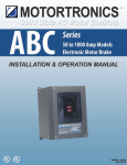
1 About the Motortronics ABC Series
1.1
General
The ABC Series is a solid state DC injection brake for stopping three- phase AC induction motors. This full-wave
DC brake design offers smooth, low peak level braking for quiet, steady operation and optimal performance.
Designed to handle even high inertia loads, the ABC Series eliminates costly and potentially dangerous "coastto- stop" times. A built-in microprocessor provides system supervision that includes digital timing control for
jogging and braking.
The integral Operator Interface Module provides LED indication of the unit's operating status and easy
adjustments for quick setup. Standard features include interlocks and mechanical brake release relays, a brake
disable input and zero speed sensing with override. Installation involves simply wiring the device into the
motor's starter circuit, which allows it to operate in parallel with the starter.
1.2
Theory of Operation
Incoming AC power is fed to terminals L1 and L2 directly from the line side of the motor starter terminals and is
converted to DC within the ABC Series. Once the motor starter has been turned off (opened) and the residual
energy in the motor has dissipated, the DC current from the ABC Series is applied (injected) to starter terminals
T1 and T2 respectively. This creates a stationary magnetic field in the AC motor stator windings.
The braking torque will increase in proportion to the amount of current allowed to flow. The rotor continuously
attempts to pull into alignment with this stationary field. This creates braking action which brings the load to a
stop faster than if it coasted to a stop.
1.3
Brake Sizing and Selection
ABC Series brakes are suitable for use in most AC motor applications where coast-to-stop times are undesirable
or unacceptable. The ABC Series is a current controlling brake, so various sizes of brake units can be applied to
various motor sizes. Because DC injection means applying power to the AC motor after turning it "Off", motor
heating (although minimal) will continue during the braking cycle and should be considered when selecting the
motor. AC motor manufacturers recommend that each braking cycle over 100% FLA be considered as an
additional starting cycle when calculating the starts- per-hour ratings for the selected motor.
If the selected ABC Series is sized to deliver 200% of motor rated current, consider each brake cycle to be 2
start cycles for these calculations (and 300% FLA = 3 "starts" per brake). Never size any DC injection brake to
exceed 400% of the motor nameplate FLA without first consulting the motor manufacturer. Additional guidelines
for applying ABC Series brakes follow:
www.motortronics.com
Page 3
Motortronics
1.3.1
Standard Duty Sizing
Applying an ABC Series brake that is rated for <115% of the FLA (Full Load Amp) rating of the motor allows
maximum length of braking time without exceeding the thermal capacity of the stator windings. Since current is
controlled by the ABC Series throughout the braking cycle, braking torque will vary as the motor circuit
impedance decreases with speed. Braking torque will be highest at the beginning of the cycle, and can be as
much as 100% of the FLT (Full Load Torque) when set to motor FLA.
As the motor slows, the braking torque slowly decreases, reducing the mechanical stresses as much as
possible. Sizing a brake in this manner is typically good for machine tools, saws, conveyors, lumber machinery,
and most chippers where the coast-to-stop time does not exceed 5 minutes. Stop times vary greatly with load
and friction, but can be expected to be 1/2 of the coast-to-stop time or less. Keep in mind that the maximum
brake time is setting is 127 seconds. In heavily loaded, high inertia machines and long coast-to-stop times, the
Standard Duty model may not stop the load. Consider using the Extra Duty rating instead.
1.3.2
Extra Duty Sizing
For heavier machine loads such as large chippers, punch presses and other flywheel based machines, selecting
an ABC Series brake based on 200-250% of the motor nameplate FLA allows faster braking. The maximum
developed braking torque can be as much as 200% of the motor rated Full Load Torque. In this case, the load
can typically stop in twice the Across-the-Line starting time. Duty cycling of the motor is a much more important
consideration in applications since additional thermal stresses due to higher current levels are applied to the
motor.
1.3.3
Custom Sizing
Extreme loads (such as overhauling conveyors or large centrifuges), or short stop times (approaching the
across-the-line starting time of the motor) may require sizing the ABC Series for 300% of the motor FLA or
greater, and should be done with careful consideration of motor heating, duty cycle, and limitations of
mechanical stress on the drive train components.
1.3.4
Emergency Stopping
An ABC Series brake used in conjunction with a mechanical brake can be considered if the stop times must be
equal to or shorter than the across-the-line start time. Consider using and ABC Series brake in conjunction with
a mechanical brake.
www.motortronics.com
Page 4
Motortronics
1.4 Applications
The ABC Series electronic brake is ideal for machine and process equipment control applications. Benefits
include, improved efficiency, increased safety, and reduced equipment maintenance costs.
Efficiency is improved because you no longer have to wait through long coast-to-stop times for blade changes,
batch loading, or maintenance shutdowns. Productive time increases while overall operating costs decrease
because the load stops much sooner. The ABC Series eliminates the common and dangerous practice of
jamming the load to a stop which seriously reduces the life and effectiveness of saw blades, molding heads, and
knives.
Safety is improved by eliminating the need to "jam-stop" equipment. This will prevent personnel injuries caused
by kickbacks and broken blades. Use the ABC Series in conjunction with safety inter- lock devices to stop the
motor as quickly as possible, reducing the risk of contact with dangerous machine elements. Prevent premature
wear or component failure and eliminate the need for hasty repairs that can put maintenance personnel in
potentially dangerous situations.
Reduce maintenance costs by using the ABC Series. The ABC series brakes can eliminate the need to plugreverse a load and the associated damage to gear boxes and other power train components. The ABC Series
can be used to stop or slow down the load in one direction before reversing to the other. On machines where
mechanical brakes are used to stop or hold a load, use the ABC Series to stop it first, then set the mechanical
brake as a "parking brake". This eliminates the normal wear and tear to the brake pads or shoes. On loads such
as vibrating feeders, screens, or separators, damage from mechanical resonance that occur during coast-down
can be eliminated by using an ABC Series. By not allowing the system to coast to a stop, the motor/load quickly
pass through any dangerous speeds where resonance can occur and come to a controlled stop.
1.5 Where Mechanical Brakes should be used
Power loss during braking - The ABC Series, like all DC injection brakes, requires power to be applied during
the braking cycle. If the incoming line power is lost, an upstream circuit protective device trips, or an emergency
shutdown is initiated, no braking will take place. If braking is still necessary for safety reasons (even in the event
of a power failure), consider using mechanical brakes as a backup device. Under normal operation conditions,
the ABC Series stops the load and the mechanical brake holds it.
Regarding holding the load after it comes to a stop - All DC injection brakes inherently lose braking torque
when the motor comes to a complete stop and therefore CANNOT BE USED AS HOLDING BRAKE. If braking
must be applied continuously while the load is at rest, mechanical "Parking Brakes" are required. The ABC
Series includes a Mechanical Brake Release Relay to facilitate proper coordination of the mechanical brake in
these applications.
Stop times shorter than start times - Like all DC injection brakes, the ABC Series waits for the residual motor
energy to dissipate from the windings before DC current can be applied (otherwise damage to the brake or
circuit devices may occur). The length of this "wait state" depends on the motor's residual magnetism and the
motor frame size, but can be several seconds. This, combined with the limits on braking torque, makes DC
injection braking ineffective if braking time must be shorter than the starting time (Across-the-Line).
WARNING!
DC Injection brakes cannot be used for holding a load after it comes to a stop. The ABC Series includes a
Mechanical Brake Release Relay that can be used to coordinate the operation of a mechanical brake for
use in these applications.
www.motortronics.com
Page 5
Motortronics
1.6
ABC Series Model Number, Rating and Dimensions
ABC - 200 -
- E
Max. Brake Amps
10 – 1000 A.
Voltage
Enclosure
240 = 208 – 240V, 400 = 380 – 415V
P = Panel Mount
480 = 440 – 480V, 600 = 575 – 600V
E = NEMA 4/12 Sealed
ABC SERIES
Typical Horsepower Usage
Model
Max
Number*
Amps
208 V
240V
Dimensions
480V
600V
Std.
Extra
Std.
Extra
Std.
Extra
Std.
Extra
Duty
Duty
Duty
Duty
Duty
Duty
Duty
Duty
Panel
NEMA 4/12
Dim Ref.#
Dim Ref. #
ABC-10
10
3
1
3
1
7.5
3
10
5
2
7
ABC-24
24
7.5
3
10
5
20
10
25
15
2
7
ABC-50
50
15
7.5
20
10
40
25
50
30
2
7
ABC-100
100
30
20
40
25
75
50
100
60
2
7
ABC-200
200
75
40
75
50
150
100
200
125
3
8
ABC-300
300
100
60
125
75
250
150
300
200
4
9
ABC-400
400
150
75
150
100
350
200
400
250
4
9
ABC-550
550
250
125
200
150
500
300
600
350
5
10
ABC-800
800
350
200
350
200
700
450
900
500
5
10
ABC-1000
1000
400
250
400
300
900
500
1000
600
5
10
NOTES:
1. Never exceed the Full Load Amp rating of the motor without checking the motor manufacturer's data
with regards to appropriateness of the application and duty cycle.
2. If duty cycle is not known, Motortronics recommends using the Extra Duty Brake since braking current
can be adjusted down to meet the actual load requirements.
Dimensions (Inches)
Dim
Ref. #
2
A
10.5
B
7.9
C
7.2
D
10
E
6.8
F
0.21
3
16.5
10
10
15.9
9
0.28
4
16
16
10
15
15
0.5
5
21
26
10.4
20
25
0.5
6
16
12
9
14.5
10.5
0.5
7
20
16
9
18.5
14.5
0.5
8
24
20
16
22.5
18.5
0.5
9
36
24
16
34.5
22.5
0.5
10
36
30
16
34.5
28.5
0.5
www.motortronics.com
Page 6
Motortronics
N4/12 Outline: ABC-10/24/50/100-E
N4/12 Outline: ABC-200-E
www.motortronics.com
Page 7
Motortronics
N4/12 Outline: ABC-300/400-E
N4/12 Outline: ABC-550/800-E
www.motortronics.com
Page 8
Motortronics
Panels Outline: ABC-10/24/50/100
Panels Outline: ABC-200
www.motortronics.com
Page 9
Motortronics
Panels Outline: ABC-300/400
Panels Outline: ABC-550/800
www.motortronics.com
Page 10
Motortronics
Panels Outline: ABC-1000
www.motortronics.com
Page 11
Motortronics
2 Operation
2.1
Sequence of Operation
The ABC Series brake becomes "Armed" when the motor starter turns "On” and then braking occurs when the
starter is turned "Off". An Operator Interface Module has two large LEDs to indicate "Braking" or "Fault"
condition, plus six smaller LEDs to indicate the following modes of operation:
2.1.1
“Power On”
The ABC Series brake is self-powered from the available motor branch circuit from Terminals L1 and L2. If fuses
are used, this LED will indicate a blown fuse condition in either of these circuits by being off when power is
applied to the starter (see section 4.2.1). This LED does NOT indicate motor starter or ABC Series brake unit
operational status.
2.1.2
Jog / Armed
The ABC Series monitors an input wired to the motor starter which indicates the starter status (see section
4.3.1). The ABC Series can be programmed to wait a specific amount of motor run time before going into the
"Armed" mode by using the "Jog" feature. This feature allows for user setup and testing of systems during the
jog time without the braking cycle interfering. (The "Jog" time is set via the "Jog Time" dip switches.) This LED
will flash once per second until the end of the jog time. If the Motor Starter is turned off while the ABC Series is
still in the "Jog" mode, the brake will NOT arm and DC injection will not take place (setting this time to zero will
turn off this feature). If the motor is run longer than the "Jog Time" and the "Jog Time" expires, the ABC Series
will enter the "Armed" mode (indicated when the JOG/ARMED LED illuminates in a steady state). The ABC
Series is now ready to begin DC injection braking the next time the motor starter is turned off. The "Armed"
mode has no time limit and will be maintained for the duration of the motor run time.
www.motortronics.com
Page 12
Motortronics
2.1.3
“Braking”
After the ABC is "Armed" and the motor starter is given a STOP Commend, the ABC Series will enter the
"Braking" mode (see "JOG / ARMED" above). To prevent damaging current spikes, the ABC monitors the motor
until the stator magnetic field decays before DC is applied (see section 5.1). Immediately upon the motor starter
opening and throughout the "BRAKING" mode, a set of N.C. interlock contacts change state (open) and disable
the motor starter control circuit during the braking cycle (see section 4.2.2).
The ABC Series begins injecting a True RMS regulated DC braking current and simultaneously digitally times,
controls the Interlock Relay and monitors the Zero Speed Sense Circuit. Braking will continue until the first one
of three events occurs: 1) the Zero Speed Sense circuit determines the motor has stopped, 2) the "Brake Time"
expires, or 3) the unit receives a "Brake Disable" signal input. When braking is complete, the ABC Series
releases the Interlock Relay and enters the "Brake Off" mode ready for another cycle.
2.1.4
Brake OFF
This LED illuminates whenever the ABC Series is not actively braking (either because the motor is on or the
previous braking cycle has been completed). The ABC Series provides a built-in, closed-loop sensing circuit that
accurately determines when the motor has stopped based on the subtle signals received from the unused motor
winding. If the Zero Speed Sensing circuit determines that the motor has come to a stop before the Brake Time
has expired, it will override the brake time setting and shut the ABC Series off. The "BRAKE OFF" LED will then
illuminate. NOTE: Since the Brake Time may expire prior to the Zero Speed override coming into play, this
circuit should not be used as a true Zero Speed indicator.
WARNING!
The ABC Series DC Injection Brake requires AC power for braking. Power loss before or during braking
will result in the loss of braking ability, which can be hazardous to personnel and/or equipment. If braking
to a stop is critical regardless of the availability of electrical power, mechanical braking should be
provided as a backup system. The ABC Series brake offers a Mechanical Brake Release Relay specifically
for this purpose.
www.motortronics.com
Page 13
Motortronics
2.2
Fault Conditions
The “FAULT” LED will illuminate when any of the following conditions occur:
2.2.1
“Disabled”
The "DISABLED" mode is activated when the ABC Series receives a command on the Brake Disable input (a
N.O. dry contact at TB1) (see section 4.3.2). This mode can be used to remove the electronic brake from the
system, and is useful in applications that only require braking at certain times during the process and during
system setup. It can also be used to cancel a "Braking" cycle that is already in progress. Note: The ABC Series
is a "smart brake" and will sense a running motor and automatically arm itself if released from the "DISABLED"
mode. Under these circumstances, the ABC Series will go through the "JOG" and "ARMED" sequence again. If
the unit has determined the motor is stopped, the brake will return to the normal ready state.
NOTE: The ABC Series Mechanical Brake Release Relay will set the mechanical brake if the ABC Series
brake unit is disabled during the braking mode. Some interface wiring may be needed depending on the
voltage and current rating of the mechanical brake coil.
2.2.2
“Wiring Error”
The ABC Series unit will recognize when the interface connections or monitored signals are not correct with
respect to the proper operation sequence. If the brake detects a miswire or an improper sequence of events, it
will "self-disable" to prevent any conflicts with the existing systems and indicate "WIRING ERROR". If this
occurs, the "Fault" LED and "Wiring Error" LEDs will illuminate. Once the miswire or wrong sequence is
corrected, the brake will automatically enable itself and resume normal operation.
2.2.3
“Over Temp”
The ABC Series has thermal sensors built into the heat sink assembly. If the heat sink approaches temperatures
too high for the SCRs, the sensors will cause a Fault, shut down the brake and illuminate the "Fault" and "Over
Temp" LEDs.
www.motortronics.com
Page 14
Motortronics
2.3
Mechanical Brake Control
The ABC Series includes a Mechanical Brake Release Relay that can be utilized to control an electromechanical brake coil. This relay has a Form “A” contact (1 N.O.) that changes state as follows (see section
4.3.4):
OPERATION
RELAY STATUS
Power On
No Change (de-energized)
Jog / Armed
Energizes, follows motor starter (Closes)
Braking
Remains energized (Closed)
Braking Time Completed /
De-energizes (Opens)
Zero Speed Override
Disabled – Before or During Jog / Armed
Follows motor starter
Disabled – During Braking
De-energizes (Opens)
Fault
De-energizes (Opens)
www.motortronics.com
Page 15
Motortronics
3 Installation
3.1
Receiving and Unpacking
Upon receipt of the product you should immediately do the following:
• Carefully unpack the unit from the shipping carton and inspect it for shipping damage.
• Verify that the model number on the unit matches your purchase order.
• Check all electrical terminals to be sure no connections were damaged during shipping.
3.2
Initial Unit Inspection
Complete a visual check of the unit for damage which may have occurred during shipping and handling. Report
any damage immediately and file a claim with the freight carrier within 15 days of receipt. Do not attempt to
continue installation.
CAUTION!
Do not operate or install the ABC Series Brake if it appears to be damaged or visually defective. Doing so
may result in personnel injury or equipment damage.
3.3
Location
Proper location of the ABC Series is necessary to achieve specified performance and normal operation lifetime.
The unit should always be installed in an area where the following conditions exist:
• Ambient operating temperature:
Ventilated Enclosure: 0 to 50°C (32 to 122°F)
Non-Ventilated Enclosure: 0 to 40°C (32 to 104°F)
• Humidity: 5 to 95% non-condensing
• Free from metallic particles, conductive dust and corrosive gas
• Free from excessive vibration (below 0.5G)
• Open panel units must be mounted in the appropriate type of enclosure. Enclosure size and type must be
suitable for environmental conditions and heat dissipated by the unit. Contact factory for details.
3.4
Mounting and Cleaning
The unit is air cooled and must be properly mounted to allow for unrestricted airflow across the heat sink. The
unit must be mounted with the heat sink fins in a vertical plane, with a minimum of five (5) inches (127mm) of
free space around the unit for adequate ventilation. The ambient air should be free of any contaminants which
can clog louvers or coat the unit. As with all electrical equipment, the unit must be protected from water and
condensing humidity to prevent possible damage. In damp or cold environments, space heaters may be
required.
WARNING!
Remove All Sources of Power Before Cleaning the Unit. In dirty or contaminated atmospheres the unit
should be cleaned on a regular basis to ensure proper cooling. Do not use any chemicals to clean the
unit. To remove surface dust, use 80 to 100 psi clean, dry compressed air only. A three inch, high
quality, dry paint brush is helpful to loosen up the dust prior to using compressed air on the unit.
www.motortronics.com
Page 16
Motortronics
4 Wiring
4.1
Introduction
• Installation of the brake unit should be done by properly qualified personnel.
• Check local and other applicable codes to ensure that all installation requirements are met prior to operation.
• Prior to beginning the installation, verify that the motor and brake unit have the same voltage ratings.
• Check the unit to verify that it is rated for the appropriate current (approximately equal to the motor FLA if
sized for Standard Duty - see section 1.3).
WARNING!
Do not service equipment with voltage applied! Unit can be source of fatal electrical shocks! To avoid
shock hazard, disconnect main power before working on the unit. Warning labels must be attached to
terminals, enclosure and control panel to meet local codes.
4.2
Line and Load Connections
Power conductors for the Brake Line and Load connections should be, at a minimum, sized at 125% of the
current rating. Brake sizing and duty cycling should be considered when determining if conductors should be
oversized for your application. For example, high torque, fast stop applications with maximum duty cycle may
require conductors sized for the maximum output capability of the ABC Series, and motor lead wires should
match.
www.motortronics.com
Page 17
Motortronics
4.2.1
Line Power Connections
Connect the line leads to the input terminals L1 and L2 provided on the unit. The line power must be supplied
from a source with suitable Short Circuit Protective Devices (SCPD) conforming to local and national electric
codes.
Additional fusing is necessary only when the motor circuit is fused at a level too high to protect the ABC Series
per code. Recommendations for commonly available SCPDs are as follows:
Circuit Breaker
Time Delay Fuse
Class RK5
Non-Time Delay Fuse
Class J
ABC-10
-
50A
50A
ABC-24
-
50A
50A
ABC-50
-
225A
225A
ABC-100
-
225A
225A
ABC-200
-
300A
300A
ABC-300
1200A
1600A
900A
ABC-400
1200A
1600A
900A
ABC-550
150% of Max. Unit Rating
150% of Max. Unit Rating
200% of Max. Unit Rating
ABC-800
150% of Max. Unit Rating
150% of Max. Unit Rating
200% of Max. Unit Rating
ABC-1000
150% of Max. Unit Rating
150% of Max. Unit Rating
200% of Max. Unit Rating
Unit
WARNING!
Many motor safety disconnect switches are not rated to interrupt DC current. Replace any load side safety
disconnect switch with one that is rated for DC voltage at the motor line voltage rating or greater. As an
alternative, disconnect incoming line power before opening any load side disconnect switches in the
motor circuit during braking, and post warning labels at all affected devices. Failure to observe this
precaution may result in damage to the disconnect and /or bodily injury
www.motortronics.com
Page 18
Motortronics
4.2.2
Power Connections
The ABC Series unit will operate on either a Wye or a Delta connected motor.
Connect the brakes L1 & L2 input terminals to the L1 & L2 terminals on the motor starter.
Connect the T1 and T2 brake output terminals to the T1 and T2 terminals on the Motor starter.
An additional sensing wire must be run from T3 (W) terminal of the starter to the voltage sensing circuit of the
ABC Series labeled T3. This terminal carries very little current so a #14 wire can be used. Proper fuse protection
for the field wiring must be provided per code.
NOTE: If the ABC Series brake is being used with 2-speed, Wye- Delta or Reduced Voltage starter, consult
factory for additional load connection information.
CAUTION!
Power Factor Correction Capacitors should NOT be connected to the load side of the motor starter when
used with an ABC Series brake. PFC Capacitors should only be connected to the line side and must
include a separate isolation contactor.
www.motortronics.com
Page 19
Motortronics
4.3
Control Connections
Control wire should be twisted, shielded cables and run in a separate conduit from power lines. Whenever
possible, conduits containing control and power conductors should cross at right angles to each other. Control
connections are made at terminal blocks mounted on the printed circuit boards inside the unit case. TB1 is on
the Logic Board with the terminals for the Starter Monitor (Brake Command) and Brake Disable inputs. TB2 is
located on the Power Board, and provides terminals for the Interlock Contacts and Mechanical Brake Relay.
WARNING!
The motor starter must never be operated manually when the brake unit is connected. Blown fuses and/or
damage to the unit may result.
4.3.1
Starter Monitor Input
Provides a status signal from the motor starter to the CPU (refer to sections 2.1.2 & 2.1.3). Connect either the
normally open, or normally closed (user preference) dry auxiliary contact on the motor starter to TB1, terminals 1
and 2 on the logic board. To utilize a normally closed contact select Jumper X1 (factory default). For a normally
open contact, move the Jumper to X2. For reversing starters, use 2 N.O. contacts in parallel or 2 N.C. contacts in
series (1 from each contactor) to this input. Circuit voltage potential: 15VDC maximum.
www.motortronics.com
Page 20
Motortronics
4.3.2
Brake Disable Input
Disables electronic braking functions before, during, or after operation (refer to section 2.2.1). To utilize this
feature, wire a N.O. dry contact to TB1 terminals 3 and 4 on the logic board. The disable feature will activate as
long as the contact is closed, and will resume operation sequence only when the disable command is released
(i.e. the contact is opened). Once the ABC Series has resumed operation, it will evaluate the status of the motor
starter, re-enter the "JOG" mode and "ARM" if conditions are correct. Circuit voltage potential: 15VDC maximum.
Note: The Brake Disable can and should be used to disable the ABC Series brake in the event of a motor
thermal overload by wiring normally open contacts from the overload relay to these terminals. This
will prevent the brake from operating if a motor over- load trip condition occurs.
www.motortronics.com
Page 21
Motortronics
4.3.3
Interlock Contacts
The ABC Series unit MUST be interlocked with the motor starter coil circuit to disable the motor starter during
the braking cycle for proper operation (refer to 2.1.3). Two sets of "FORM C" contacts are provided on TB2 on
power board to interlock the motor starter with the brake. Terminals 1, 2, and 3 are the first set and terminals 4,
5, and 6 are the second. Use both sets for reversing starters, each in one of the contactor coil circuits. The
second set may be used as a status indicator in non-reversing starter applications. Never connect the interlock
contacts parallel to the contactor coil or across the power line. Circuit voltage potential: same as starter control
circuit, 240VAC maximum.
WARNING!
If this wiring is done incorrectly or not at all, severe damage to the unit may occur and the warranty on
the unit may be voided.
4.3.4
Mechanical Brake Release Relay
The ABC Series brake unit can work in conjunction with a mechanical brake by interfacing with the motor and
allowing for mechanical brake control. The ABC Series brake can be used for stopping, and the mechanical
brake for holding. The Mechanical Brake Release contacts are N.O. relay contacts rated for 5A, 250VAC and are
located at terminals 7 and 8 of TB2 on the Power Board (see section 2.3 for additional operating details).
The unit will detect the motor start command and release the mechanical brake. When the stop command is
given, the ABC Series brake unit will continue to keep the mechanical brake released, proceed with the DC
injection braking sequence, then engage the mechanical brake at the end of the braking cycle. If the disable
feature is engaged while in "BRAKING" mode, the ABC Series will automatically set the mechanical brake.
www.motortronics.com
Page 22
Motortronics
5 Adjustments
5.1
Time Adjustment Procedures
Time settings for "Jog Time" and "Brake Time" are adjusted by use of dip switches on the front mounted Operator
Interface Module. Time settings are in seconds (set in binary code). Each switch denotes a binary digit from 1 - 7
positions, totalling 127 seconds maximum when all are switched to the "On" position.
Operator Interface Module
5.2
Jog Time Adjustment
Factory Setting: 3 seconds
The jog time is adjustable from 0-127 seconds and is made using the 7 position dip switch SW2, labeled "Jog
Time". Set the switches according to the jog time required. Setting all the switches to the "Off" position (Jog
Time = 0) will disable this function.
Switch Positions
On
Example:
Setting dip switch positions 1, and 2 to “ON” = 1+2
Jog Time
= 3 seconds total jog time.
1
2
3
4
5
6
7
Time (sec.) 1 2 4 8 16 32 64
CAUTION!
Damage to the motor, equipment, brake and/or electrical circuit may occur if this adjustment is not
correct. Setting this switch to less than the factory setting may involve risk to the equipment and affect
normal operations. Setting the jog time too long may result in equipment operating without the benefit of
the DC injection brake. The jog time should typically be set to equal the time it takes the motor to
accelerate the load to full speed (across- the-line) plus approximately two seconds.
www.motortronics.com
Page 23
Motortronics
5.3
Brake Time Adjustment
Factory Setting: 7 seconds
The brake time is programmable from 1 to 127 seconds. Set the switches marked "Brake Time" to the brake
time required. Typical brake time settings should be 1/2 of the load's coast-to-stop time or less, as necessary.
Each dip switch represents a binary time value. Add the times together for the final brake time setting
Switch Positions
On
Example:
Setting dip switch positions 1, 2, and 3 to "ON" = 1+2+4
Brake Time
= 7 seconds total brake time.
Time (sec.)
1
2
3
4
1
2
4
8 16 32 64
5
6
7
NOTE: Stop times shorter than 4 seconds will not allow enough time for the Zero Speed Sensing circuit to
accurately sense that the motor has stopped. For stopping times shorter than 4 seconds, Brake Time must be
used to turn the ABC Series off to insure proper stopping.
5.4
Brake Current Adjustment
Factory Setting: 50% of Unit Rating
It is strongly recommended that you try the factory settings first before making any adjustments. First determine
if adjustments are necessary by verifying the motor came to a stop during the braking cycle. If not, first increase
the Brake Time setting and repeat the test. If after increasing the Brake Time setting to the desired maximum the
motor still does not come to a stop during braking, increasing the Brake Current may be necessary. To do so, a
"True" RMS AC clamp-on ammeter is needed to measure the current supplied to the motor while braking. To
monitor the current, place the meter on one of the ABC Series' input power lines. Start the motor by energizing
the motor starter contactor. Allow the motor to come up to full speed with the normal load. Engage the brake by
de-energizing (stopping) the motor starter contactor. Then, measure the brake current. If necessary, slowly
adjust the brake torque potentiometer (P1) (located in the Operation Interface Module) clockwise to increase the
braking current. The braking Current and Time Settings should be adjusted so that the braking time expires at
the same time the motor stops. Adjust the brake Time and/or Current until acceptable. Start and stop the motor
several times to verify proper operation.
WARNING!
Never exceed the RMS full load current rating of the motor without first checking with the motor manufacturer for
the maximum allowable amount of DC current that can be supplied to the motor during braking application.
www.motortronics.com
Page 24
Motortronics
Application Specific Adjustments
CAUTION!
These settings are factory preset to provide optimum performance in a wide variety of applications, and should
not be changed unless the user is specifically aware of the risks and consequences (contact factory for details).
Disconnect all incoming power and observe anti-static control measures when making any of the following
configuration changes.
Brake On Delay (Switch SW1)
This DIP switch controls the amount of time the ABC Series brake waits prior to applying DC current to the motor
windings. It is Factory Configured for the Automatic Mode in order to allow the stator magnetic field to decay.
The rate of decay varies with motor size, so this SHOULD NOT BE CHANGED. Changing this setting could
result in damage to the ABC Series components and circuit protective devices. If your application requires a
specific delay time, please contact the factory for assistance.
Zero Speed Sensing Disable (Jumper X3)
If for some reason you need to disable the Zero Speed Sensing, remove this jumper. The ABC Series will then
continue braking for the entire Brake Time setting, even if the motor has already come to a complete stop. DO
NOT disconnect the sensing lead to the "T3" terminal as that will cause a "Wiring Error" fault disabling the brake.
Therefore this should not be used as a means of disabling the Zero Speed Sense circuit.
50 Hz Operation (Power Board Jumper X1)
Remove this jumper on units required to operate at 50 Hz.
CAUTION!
Some adjustments and devices visible on the ABC Series boards are preset at the factory and should NOT
be field adjusted without specific instructions from factory authorized service personnel. These devices
include: P1 and P2 potentiometers, and push button PB1. Tampering or altering these devices may void
your warranty.
www.motortronics.com
Page 25
Motortronics
6 Start-up
6.1
•
•
•
•
•
Start-up Check List
Verify that the supply voltage matches the supply voltage of the ABC Series brake.
Confirm that the power lines are attached to the input terminals.
Verify that the output leads are connected to the output terminals.
Complete the appropriate control and interlock connections.
Clear the area of people and extra parts before start up.
NOTE: For 50 Hz operation, be sure that jumper X1on the Power Board is removed.
6.2
Equipment
The following equipment will be needed for start-up:
• A "true" RMS AC clamp-on ammeter to check braking current.
• A small screw driver to adjust braking torque (if necessary).
• A digital volt meter.
• Stop watch or other means of measuring time.
6.3
Setup Sequence
•
•
•
•
Start the motor by energizing the motor starter.
Allow the programmed jog time to expire. (Factory set for 3 sec.)
De-energize the motor starter to initiate brake mode.
Monitor the input current to the ABC Series unit on any one of its input leads with the "true" RMS AC
clamp-on ammeter.
• Adjust the brake current if necessary.
• If the brake times out before the motor stops, increase the value of the brake time switch, or increase the
brake current (Note: Never exceed the RMS rating of the motor without checking with the motor
manufacturer).
• If the Zero Speed Sense option engages and turns off the brake before the programmed brake time
expires, adjust the brake time dip switch for approximately two (2) seconds longer than the actual stop
time.
6.4
Check Normal Sequence of Operation
Apply power to the system. The "Power On" LED should indicate that the line power is correct. Both the "Power
On" and the "Brake Off" LED should be illuminated.
• Start the motor. The "Jog / Armed" LED should flash once per second to indicate programmed Jog Time.
• Allow the motor to run until the "Jog / Armed" LED should light solid.
• Initiate the motor stop command. The "Brake Off" LED should go out and the "Brake On" LED should
illuminate. The unit should begin braking and continue braking, until the motor comes to a stop or the
programmed brake time expires.
www.motortronics.com
Page 26
Motortronics
APPENDIX A: Technical Specifications
Voltage Rating:
Models rated from 208 – 600 +/- 10%
Line Frequency:
Selectable for 50 / 60 Hz + 2Hz
Current Ratings:
10 – 1000A
10, 24, 50, 100, 200, 300, 400, 550, 800, 1000A
Output Capacity:
25% duty cycle at 100% unit rating. 10A-400A are UL duty cycles.
10& 24A = 100%
50 thru 200A = 25%
300A thru 800A = 15%
1000A = 25%
Power Circuit:
Full wave bridge, 4 SCRs, designed for use without isolation
contactors.
Transient Protection:
RC snubber dv/dt circuit on each SCR device.
Fusing:
Refer to section 4.2.1 for branch circuit protection requirements.
Control Circuit:
Self-powered directly from line terminals. No separate control
voltage required.
Control Method:
Microprocessor unit control sequencing, I/O monitoring and status
annunciation. Braking current is adjustable via true RMS regulated
control using phase angle firing of SCRs.
Operator Adjustments:
Brake Time and Jog Time = 7 position binary dip-switch.
Brake Current = potentiometer
Adjustment Ranges:
Brake Jog Time = 0 – 127 seconds in 1 sec. increments.
Brake Current = Up to 100% of unit rating.
Inputs:
Starter Monitor = Dry input for auxiliary contact from motor starter.
Jumper selectable for N.O. or N.C. contact.
Inputs:
Brake Disable = Dry input for N.O. contact to disable braking before
or during operation. Can be wired to the starter thermal overload
N.O. auxiliary contact to prevent braking of overloaded motor.
Motor Power Sensor (T3) = Voltage input used for sensing motor
power presence in sequencing / status circuit and for zero speed
sensing during braking.
www.motortronics.com
Page 27
Motortronics
Outputs:
Starter Coil Interlock = Two sets of FORM “C” relay contacts for use
in interlocking the starter coil and/or other devices to prevent
energizing while the braking power is applied.
Mechanical brake Release = N.O. relay contact for use in controlling
electro-mechanical brake as a holding brake. When the ABC Series
is “disabled”, this circuit controls the mechanical brake normally as if
it is the only brake in the system.
Aux. Contact Ratings:
5 Amps, 250 VAC max.
LED Status Indicators:
Large LEDs: braking = green; Fault = Red
Small LEDs: Power On, Jog/Armed, Brake Off, Disabled, Over
Temp and Wiring Error.
Operating Design Temperature:
32ºF – 122ºF / 0ºC to 50ºC
Storage Temperature:
-4ºF – 176ºF / -20ºC to 80ºC
Ambient Conditions:
5% to 95% relative humidity
0 – 3300ft (1000m) elevation
Approval:
UL, cUL Listed
www.motortronics.com
Page 28
Motortronics
Warranty information
Motortronics warrants its products to be free from defects in material and/or workmanship for a period of one
year from the date of installation, to a maximum of 18 months from the date of shipment as indicated by the
unit's date code. The Company reserves the right to repair or replace any mal- functioning units under warranty
at their option. All warranty repairs must be performed by the Company factory or on site by factory authorized
service firms or personnel approved by the Company.
Solid state controls have different operating characteristics from those of electromechanical equipment. Because
of these differences and the wide variety of applications for solid state controls, each application designer must
verify that the solid state equipment is acceptable for his application. In no event will Motortronics be liable or
responsible for indirect or consequential damages resulting from the use or application of this equipment. The
diagrams and illustrations in this document are included solely for illustrative purposes. Because of the number
of different applications, Motortronics cannot be responsible or liable for actual use based on the examples or
diagrams.
www.motortronics.com
Page 29
For the latest product information
visit www.motortronics.com
Phasetronics Inc. dba as Motortronics
1600 Sunshine Drive
Clearwater, Florida 33765
USA
Tel: 727.573.1819 or 888.767.7792
Fax: 727.573.1803 or 800.548.4104
E-Mail: [email protected]
Manual 0011002
Rev 2.0.0.4
08/30/12