1
XLD Series
Digital Solid State Soft Starter 39 - 1250A
™
XLD SERIES
Digital
Solid State Soft Starter
39 - 1250 A
INSTALLATION & OPERATION
MANUAL
REV2.1 01032601MN
© 2012, Phasetronics Inc. dba as Motortronics
Motortronics™
-1-
XLD Series
Digital Solid State Soft Starter 39 - 1250A
Motortronics™
-2-
XLD Series
Table of Contents
Digital Solid State Soft Starter 39 - 1250A
XLD Series
Digital Solid State Soft Starter
39 - 1250A
Chapter 1: Introduction .....................................................1
1.1 General
1.2 Specifications and Performance Features
Chapter 2: Installation ....................................................... 4
2.1 Receiving and Unpacking
2.2 Location
2.3 Initial Unit Inspection
2.4 Warning
2.5 Mounting and Cleaning
2.6 Power Terminal Wire Range and Tightening Torque
2.7 Dimensions
Chapter 3: Motor Overload Protection ...........................7
3.1 Solid State Overload Protection
3.2 NEMA Class Trip Curves
Chapter 4: Connections ..................................................10
4.1 Power Connections
4.2 Control Connections
4.3 Interlock Connection
Chapter 5: Programming ................................................13
5.1 Introduction
5.2 Digital Interface
5.3 Display Modes
5.4 Function List
5.5 Function Descriptions
Chapter 6: Start-Up.......................................................... 32
6.1 Quick Start
6.2 Start-up Check List
6.3 Sequence of Operation
Chapter 7: Fault Conditions ........................................... 35
7.1 Fault Codes and Numbers (In History)
Chapter 8: Troubleshooting ........................................... 36
8.1 Failure Analysis
8.2 SCR Testing Procedure
8.3 Replacing SCR Devices
8.4 Replacing Printed Circuit Board Assembly
Chapter 9: Printed Circuit Board Layout ....................... 44
9.1 Typical Wiriing Diagram
9.2 Power Board and CPU Board (PC Board Assembly)
Appendix 1: Ramp Profile Details
Appendix 2: Decel Mode Application Considerations
Appendix 3: Parameter Lock / User Password Instructions
Appendix 4: Soft Starter Settings
Warranty Policy
Motortronics™
-3-
XLD Series
Digital Solid State Soft Starter 39 - 1250A
Motortronics™
-4-
XLD Series
Digital Solid State Soft Starter 39 - 1250A
Chapter 1 - Introduction
1.1
General
The XLD Series is a digitally programmable solid state reduced voltage
soft starter. Its six SCR design features a voltage/current ramp with an
anti-oscillation circuit for smooth load acceleration. The SCRs are sized
to withstand starting currents of 500% for 60 seconds (compared to
350% for 30 seconds from other manufacturers). The XLD Series
features smooth, stepless ramp control which reduces motor inrush
current and excessive wear on the mechanical drive train components.
In addition to having easy to understand diagnostic LEDs, the XLD
Series includes a programmable keypad for setting operating
parameters for the ideal starting cycle. Starting torque, ramp time, current
limit, dual ramp, and decel control are standard features on the XLD
Series. By simply adjusting the unit’s starting torque, ramp time and
current limit functions, the starting electrical characteristics of the motor
can be matched to the mechanical characteristics of the drive train for
controlled acceleration of the load. The XLD Series includes solid state
electronic overload protection in addition to numerous other protective
features. It is factory wired for 120 VAC control voltage and two or threewire start/stop control (Units can also be ordered with 240 VAC control
voltage if required). Programmable auxiliary contacts and provisions
for interlocking are also included.
1.2
Specifications and Performance Features
Type of Load
Three phase AC induction motor
AC Supply Voltage
208 - 600VAC ±10%, 50/60 Hz
HP Ratings
39 - 1250 Amps, 10 - 1125 HP
Unit Overload Capacity
(Percent of motor FLA)
125% - Continuous
500% - 60 seconds
600% - 30 seconds
Power Circuit
6 SCRs
SCR Diode Ratings
(Peak Inverse Voltage)
1600V
Phase Insensitivity
Unit operates with any phase sequence
Transient Voltage Protection
RC snubber dv/dt networks on each phase.
Cooling
Convection up to 180A, fan assisted 62 - 120A,
Fan ventilated 220 - 1250A
Bypass Contactor
Shunt rated contactor included as standard in all NEMA 12
enclosed units 92A and above. Also standard with all NEMA
12 combination starters. Line start rated contactor available
as an option.
Ambient Condition Design
Chassis units: 0° to 50 °C (32° to 122°F)
Enclosed units: 0° to 40°C (32° to 104°F)
5 - 95% relative humidity
0 - 3300 ft. (1000m) above sea level without derating
Control
2 or 3 wire 120VAC (customer supplied)
Optional 240VAC control voltage and CPTs are available.
Type / Rating: Form C (SPDT), rated 5 Amps,
240VAC max. (1200VA)
Auxiliary Contacts
3 Programmable Relays
Fault Indicator: AC triac solid state switch
240VAC, 50mA max.
Approvals
UL Listed, Canadian UL (cUL) Listed
Motortronics™
-1-
XLD Series
Digital Solid State Soft Starter 39 - 1250A
1.2
Specifications and Performance Features Cont’d
Advanced Motor Protection
Two Stage Electronic
Overload Curves
Starting: Programmable for Class 5 through 30
Run: Programmable for Class 5 through 30 when "At-Speed"
is detected.
Overload Reset (Note 1)
Manual (default) or automatic
Retentive Thermal Memory
Overload circuit retains thermal condition of the motor
regardless of control power status. Unit uses real time clock
to adjust for off time.
Dynamic Reset Capacity
Overload will not reset until thermal capacity available in the
motor is enough for a successful restart. Starter learns and
retains this information by monitoring previous successful
starts.
Phase Current Imbalance
Protection (Note1)
Imbalance Trip Level: 5 - 30% current
between any two phases
Imbalance Trip Delay: 1 -20 seconds
OverCurrent
(Electronic Shear Pin)
Protection (Note 1)
Trip Level: 50 - 300% of motor FLA
Trip Delay: 1 - 20 seconds
Load Loss Trip Protection
(Note 1)
Under Current Trip Level: 10 -90 % of motor FLA
Under Current Trip Delay: 1 - 60 seconds
Coast Down (Back Spin)
Lockout Timer (Note 1)
Coast Down Time Range: 1 - 60 minutes
Starts-per-hour Lockout Timer
(Note 1)
Range: 1 - 10 successful starts per hour
Time between starts: 1 - 60 minutes between start attempts
Programmable Outputs
Type / Rating
Form C (SPST), Rated 5 amps
240 VAC max, (1200 VA)
Run Indication
Start/Stop or Start/End of Decel
At Speed Indication
At Speed/Stop or At Speed/End of Decel
Acceleration Adjustments
Programmable Ramp Types: Voltage or Current Ramp
(VR or CR)
Starting Torque: 0 - 100% of line voltage (VR)
or 0 - 600% of motor FLA (CR)
Ramp Time: 1 to 120 seconds
Current Limit: 200 - 600% (VR or CR)
Dual Ramp Settings
4 Options: VR1+VR2; VR1+CR2; CR1+CR2; CR1+VR2
Dual Ramp Control: Ramp #1 = Default,
Ramp = #2 selectable via dry contact input
Deceleration Adjustments
Begin Decel Level: 0 - 100% of line voltage
Stop Level: 0 to 1% less than Begin Decel Level
Decel Time: 1 - 60 seconds
Programmable to decel or coast to stop upon overload trip
Jog Settings
Jog function selected via
dry contact closure input)
Voltage Jog: 5 - 100%
Time of Voltage Jog: 1 - 20 seconds
Current Jog: 100 - 500%
Kick Start Settings
(Note 1)
Kick Voltage: 10 - 100%
Kick Time: 0.1 - 2 seconds
Fault Indications
Shorted SCR, Phase Loss, Shunt Trip, Phase Imbalance
Trip, Overload, Overtemp, Overcurrent, Short Circuit, Load
Loss, or Any Trip
Lockout Indicator
Coast Down Time, Starts Per Hour,
Time Between Starts, and Any Lockout
Note 1: Enabled via programming
Motortronics™
-2-
XLD Series
Digital Solid State Soft Starter 39 - 1250A
1.2
Specifications and Performance Features Cont’d
Metering Functions
Phase Currents
0 - 9999 Amps, Phase A, B, or C
Remaining Thermal Capacity
0 - 100% of available motor thermal capacity
Elapsed Time
0 - 9,999,000.0 hours, non resetable
Run Cycle Counter
0 - 99,990,000 run commands non resetable
Lockout Time Values
Remaining time of any enabled lockout timer
Fault Codes
Abbreviated fault codes, indicating trip and operating mode
Fault History
Last 3 faults with Time and Date Stamps
Serial Communications
Protocol
Modbus RTU
Signal
RS-485
Network
Up to 247 devices per mode
Functionality
Full operation, status view, and programming
via communications port
LED Readout
4 digit alpha numeric, high brightness, 7 segment display
Keypad
7 functions keys with tactile feedback
Status Indicators
8 LEDs
Remote Mount Capability
Up to 10 feet (3 meters) from chassis
Clock and Memory
Operating Memory
DRAM loaded from EPROM and EEPROM at initialization
Factory Default Storage
Flash EPROM, field replaceable
Customer Settings and Status
Non-volatile EEPROM, no battery backup necessary
Real Time Clock
Lithium ion battery for clock memory only,
10+ years life span
Operator Interface
Motortronics™
-3-
XLD Series
Digital Solid State Soft Starter 39 - 1250A
Chapter 2 - Installation
2.1 Receiving and Unpacking
Upon receipt of the product you should immediately do the following:
• Carefully unpack the unit from the shipping carton and inspect it for
shipping damage (if damaged, notify the freight carrier and file a
claim within 15 days of receipt).
• Verify that the model number on the unit matches your purchase
order.
• Confirm that the ratings sticker on the unit matches or is greater
than the motor’s HP and current rating.
2.2
Location
Proper location of the XLD Series is necessary to achieve specified
performance and normal operation lifetime. The XLD Series should
always be installed in an area where the following conditions exist:
• Ambient operating temperature:
Chassis unit:
0 to 50°C (32 to 122°F)
Enclosed unit: 0 to 40°C (32 to 104°F)
• Protected from rain and moisture
• Humidity: 5 to 95% non-condensing
• Free from metallic particles, conductive dust and corrosive gas
• Free from excessive vibration (below 0.5G)
• Open panel units must be mounted in the appropriate type of
enclosure. Enclosure size and type must be suitable to dissipate
heat generated by the soft starter. Contact factory for assistance in
sizing enclosures.
2.3
Initial Unit Inspection
• Make a complete visual check of the unit for damage which may
have occurred during shipping and handling. Do not attempt to continue
installation or start up the unit if it is damaged.
• Check for loose mechanical assemblies or broken wires which may
have occurred during transportation or handling. Loose electrical
connections will increase resistance and cause the unit to function
improperly.
• Prior to beginning the installation, verify that the motor and XLD unit
are rated for the proper amperage and voltage.
2.4
Warning!
Do not service equipment with voltage applied! The unit can be
the source of fatal electrical shocks! To avoid shock hazard,
disconnect main power and control power before working on
the unit. Warning labels must be attached to terminals, enclosure
and control panel to meet local codes.
Motortronics™
-4-
XLD Series
Digital Solid State Soft Starter 39 - 1250A
2.5
Mounting and Cleaning
When drilling or punching holes in the enclosure, cover the electrical
assembly to prevent metal filings from becoming lodged in areas which
can cause clearance reduction or actually short out electronics. After work
is complete, thoroughly clean the area and reinspect the unit for foreign
material. Make sure there is sufficient clearance (six inches) all around the
unit for cooling, wiring and maintenance purposes. To maximize effective
air flow and cooling, the unit must be installed with its heat sink ribs oriented
vertically and running parallel to the mounting surface.
Warning!
Remove all sources of power before cleaning the unit.
In dirty or contaminated atmospheres the unit should be cleaned on a regular
basis to ensure proper cooling. Do not use any chemicals to clean the unit.
To remove surface dust use 80 to 100 psi, clean, dry compressed air only.
A three inch, high quality, dry paint brush is helpful to loosen up the dust
prior to using compressed air on the unit.
2.6
Model
Number
Max
Amps
XLD-39
XLD-48
XLD-62
XLD-78
XLD-92
XLD-120
XLD-150
XLD-180
XLD-220
XLD-288
XLD-360
XLD-414
XLD-476
XLD-550
XLD-718
XLD-862
XLD-1006
XLD-1150
XLD-1200
XLD-1250
39
48
62
78
92
120
150
180
220
288
360
414
476
550
718
862
1006
1150
1200
1250
Max HP
Power Terminal Wire Range and Tightening Torque
KW
208V 230V 480V 600V 230V 400V
10
15
20
25
30
40
50
60
75
100
125
150
200
250
300
350
400
450
15
20
25
30
40
50
60
75
100
125
150
200
250
300
350
400
450
500
25
30
40
50
60
75
100
125
150
200
250
300
350
400
500
600
700
800
900
1000
30
40
50
60
75
100
125
150
200
250
300
350
400
500
600
700
800
900
1000
1125
11
18.5
22
15
30
22
37
45
30
55
45
75
55
90
110
75 132
110 160
200
132 250
160
200 315
400
Model Number
XLD-39
Wire range
Torque lbs/in
#18 - #4
20
#14 - #4
50
#14 - #1/0
50
#6 - 250 kcmil
325
(2) #6 - 250 kcmil
325
(2) #2 - 250 kcmil
375
(3) #2 - 600 kcmil
375
(4) 300 kcmil - 800 kcmil
500
XLD-48
XLD-62
XLD-78
XLD-92
XLD-120
XLD-150
XLD-180
XLD-220
XLD-288
XLD-360
XLD-414
XLD-476
XLD-550
XLD-718
XLD-862
XLD-1006
XLD-1150
XLD-1200
XLD-1250
Note: All wiring must be sized according to NEC standards.
Motortronics™
-5-
XLD Series
Digital Solid State Soft Starter 39 - 1250A
2.7 Dimensions
Enclosure
PANEL
NEMA1
Model
Number
NEMA12
10
Mounting
Dimensions
D
E
F
XLD-39 to XLD-120
16.5
10
XLD-150 to XLD-180
20
20.1
12
18.5
17.5
0.44
XLD-220 to XLD-288
27
20.1
11.2
25.5
17.5
0.44
XLD-360 to XLD-550
29.5
20.1
11.5
25.5
17.5
0.44
XLD-718 to XLD-1006
45
33
12.8
43.3
31.3
0.44
15.9
9
0.28
XLD-1150 to XLD-1250
33
33
15.2
31.2
31.2
0.44
XLD-39 to XLD-120
16.5
10
10
15.9
9
0.28
XLD-150 to XLD-180
32.3
24.3
13.3
31.3
18
0.44
XLD-220 to XLD-288
38.3
24.3
13.3
37.3
18
0.44
XLD-360 to XLD-550
44.3
30.3
13.3
43.3
24
0.44
XLD-718 to XLD-1006
50.2
36.3
15.5
Contact Factory
XLD-1150 to XLD-1250
NEMA 4/4X
Overall
Dimensions
A
B
C
49.3
30
0.4
Contact Factory
XLD-39 to XLD-78
15.7
12.2
10
12
11
0.28
XLD-92 to XLD-120
24
24
12.9
22.5
22.5
0.5
XLD-150 to XLD-288
36
30
16.9
34.5
28.5
0.5
XLD-360 to XLD-550
48
36
16.9
46.5
34.5
0.5
Floor Mounted
Contact Factory
XLD-718 to XLD-1006
XLD-1150 to XLD-1250
Motortronics™
-6-
72.1
48.1
20
Contact Factory
XLD Series
Digital Solid State Soft Starter 39 - 1250A
Chapter 3 - Motor Overload Protection
3.1
Solid State Overload Protection
The XLD Series Starter provides true U.L. listed I2T Thermal Overload Protection
as a built-in function of the main digital processor. For maximum protection it
simulates the tripping action of a bimetallic overload relay, with the accuracy
and repeatability of a digital control system, yet is adjustable over a wide range
and can be easily programmed for different trip curves.
3.1.1 Thermal Memory
The XLD Series microprocessor uses a sophisticated “Thermal Register” to
keep track of motor heating and cooling over time regardless of the starter’s
power status. The XLD Series does not “forget” that the motor has been running
even if power to the starter is turned off and back on. Continuous overload
protection is provided based on the true thermal condition of the motor.
3.1.2 Thermal Capacity
The Thermal Register is displayed as a percentage. This percentage is the
motor’s remaining thermal capacity. The percentage value begins at 100, showing
that the motor is cool. As the motor heats up or moves toward an overload
condition, the percentage begins to drop. The Thermal Capacity is derived from
the programmed motor nameplate Full Load Amps (FLA) in Function F001, the
Service Factor rating in Function F002, and the Overload Trip Class in Functions
F003 and F004. Setting these functions to the proper values will provide maximum
protection yet eliminates nuisance tripping.
3.1.2.a Motor Full Load (FLA) Setting
Use Function F001 to enter motor FLA as indicated on the motor nameplate.
(Do not calculate for service factor, this is programmed separately in F002).
Note:
If F001 is left at the factory default, the unit will not operate. If the user attempts
to start the XLD without entering the motor nameplate FLA into this Function,
the XLD will Fault, and the display will read “nFLA” (for no Full Load Amps).
3.1.3 Disabling the Overload Protection
The Overload Protection feature can be disabled if absolutely necessary. When
using external devices such as Motor Protection Relays or when the XLD Series is
wired downstream from an existing starter, this feature can be disabled to prevent
conflicts with external overload protection devices. When the XLD Series is controlling
multiple motors, Overload Protection must be disabled. Individual thermal overload
relays must be installed on the motor leads going to each motor. To disable the
Overload Protection function, use F005. (See Section 5.)
Warning: Do NOT disable Overload Protection unless another Thermal
Overload Protection device exists in the circuit for all three phases.
Running a motor without Overload Protection presents serious risk of
motor damage or fire.
3.1.3.a Manual Reset
The factory default setting is Manual Reset. This means that when the Overload
Trip is activated, the starter cannot be restarted without pressing the Reset key.
The Overload Trip will not reset until the motor cools down. The Manual Reset
function is also “trip free”. Holding in the Reset key will not prevent the Overload
Trip from activating and protecting the motor.
Note:
When the Overload Trip activates, the Overload LED will glow solid. When the
motor cools down, the LED will begin to flash, indicating that the Overload
Trip can be reset.
Motortronics™
-7-
XLD Series
Digital Solid State Soft Starter 39 - 1250A
3.1.3.b Automatic Reset
If Automatic Reset is necessary, change from Manual Reset to Automatic Reset
by using Function F005. (See Section 5 for details). In this mode, a 3-wire control
circuit will be capable of restart when the XLD Series has reset itself after the
cool down period.
Warning: Two-wire control systems may restart without warning when
Auto Reset is selected. Extreme caution should be exercised. To prevent
automatic restarting with two-wire control systems, use external
interlocking to provide sufficient warning and safety to operators. A
Warning Label (such as the one provided in the packet with this manual)
must be placed to be visible on the starter enclosure and/or the
equipment as required by local code.
WARNING: MOTOR CONNECTED TO THIS EQUIPMENT MAY
START AUTOMATICALLY WITHOUT WARNING
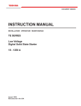
3.2
NEMA Class Trip Curves
The XLD Series Soft Starter provides six NEMA Class trip curve options: 5, 10,
15, 20, 25, and 30. Program the appropriate curve according to the characteristics
of your motor and load.
NEMA Class trip curves are based on a common tripping point of 600% of
rated current. Curves vary by the amount of time before the unit trips. As an
example, a Class 20 curve will trip in 20 seconds at 600%. The factory default
setting of Class 10 will trip in 10 seconds at 600%.
3.2.1 Dual Overload Trip Curves
The XLD Series Soft Starter provides two separate Overload Trip Protection
Curves, one for starting and one for running conditions. Programming a higher
NEMA Class overload during start (ramp-up) will eliminate nuisance tripping in
higher inertia or high friction loads.
The starter’s At-Speed detection circuit determines when the motor has reached
full speed based on closed loop feedback signals. When the At-Speed condition
is reached, the overload trip curve will shift from the Start to the Run level, as
programmed in Functions F003 and F004. See Section 5 for programming details.
Motortronics™
-8-
XLD Series
Digital Solid State Soft Starter 39 - 1250A
Time in Seconds
XLD Series
Overload Trip Curves
Class 30
Class 25
Class 20
Class 15
Class 10
Class 5
MFLA
Note: Factory default setting is Class 10 for both Start and Run Overload Protection
Motortronics™
-9-
XLD Series
Digital Solid State Soft Starter 39 - 1250A
Chapter 4 - Connections
4.1 Power Connections
Connect appropriate power lines to the unit input terminals marked L1, L2, L3.
Avoid routing power wires near the control board. Connect the motor leads to
the unit terminals marked T1, T2, T3. Refer to NEC standards for wire length
and sizing. Never interchange input and output connections to the unit. This
could cause excessive voltage in the control logic circuit and may damage the
unit.
Warning: Never connect power factor correction capacitors on the load
side of the unit. The SCRs will be seriously damaged if capacitors are
located on the load side.
The unit cannot be tested without a motor or other test load connected to the
load side of the unit. It may be necessary to use a load bank to test the unit
without a motor. Note that line voltage will appear across the output terminals if
there is no motor or load connected to the unit. In areas where lightning is a
significant problem, stationary air gap lightning arrestors should be considered
and utilized on the input power source.
XLD Series Unit
Power Connections
4.1.1 Grounding
Connect the ground cable to the ground terminal as labeled on the unit. Refer to
the National Electrical Code for the proper ground wire sizing and be sure that
the ground connector is connected to earth ground.
4.2 Control Connections
4.2.1 Control Power Connections
TB1
120V
Control
Power
Source
120V
Control
Power
Return
Separate 120VAC supply is required (order 240 VAC if required). The control
voltage should be connected to pins 1 and 6 of TB1. This control voltage must
be customer supplied, unless an optional control power transformer (see chart)
has been supplied with the unit. The terminal block TB1 is located on the main
power board. However, on units rated 150 Amps and above, TB1 is brought out
to a duplicate terminal block on the back panel assembly.
XLD Model
(by Amps)
Recommended Transformer
Sizes
Panel
NEMA 1
Up to XLD-180
50 VA
100 VA
250 VA*
XLD-220
50 VA
100 VA
500 VA*
XLD-288 to XLD-360
250 VA
250 VA
500 VA*
XLD-414 to XLD-550
250 VA
250 VA
750 VA*
XLD-718 to XLD-862
500 VA
500 VA
1 KVA*
XLD-1006 to XLD-1150
500 VA
750 VA
1.5 KVA*
XLD-1200 to XLD-1250
500 VA
750 VA
1.5 KVA*
Unit comes standard with
120VAC control. Order 240VAC
control as an option if required.
NEMA 4/12
Recommended Transformer Sizes for Control Power
Note:
If power is used for additional accessory items (Lights, fans, etc.) contact
factory for sizing.
Motortronics™
- 10 -
XLD Series
Digital Solid State Soft Starter 39 - 1250A
4.2.2 Three-Wire Connection
For standard 3-wire control connect 120VAC to pins 1 and 6 of TB1. Connect
N.C. (normally closed) stop button between pins 3 and 4 of TB1. Connect N.O.
(normally open) start button between pins 4 and 5 of terminal block TB1.
TB1
Control
Power
Source
Control
Power
Return
Three-Wire Connection
4.2.3 Two-Wire Connection
An alternate connection for unattended operation replaces start/stop push
buttons by connecting a maintained contact closure between pins 3 and 5 on
TB1. When the maintained contact is used for start/stop it is necessary to set
the overload relay to the manual reset position. This will prevent the motor from
restarting if the thermal overload trips and then cools off.
Warning: When two-wire connection method is used, the user’s control
circuit must be interlocked to prevent automatic restart when
protective devices reset. Refer to section 3.1.3.b.
TB1
Control
Power
Return
Control
Power
Source
Two-Wire Connection
4.2.4 Relay Contacts
All the relay contacts are FORM C common (N.O., N.C.), except the optical
triac output. Motortronics recommends fusing all contacts with external fuses.
TB2 is the terminal block for all auxiliary contacts. Each contact is explained in
the following sections. See Chapter 9 for main control board layout.
4.2.5 Programmable Relays
Three programmable relays are on TB2 which is located on the main control
board. The relays are rated for 240 VAC, 5 A and 1200 VA.
Factory settings for these relays are:
AUX 1 - Run / Stop (F050 = 1)
AUX 2 - At Speed / Stop (F051 = 2)
AUX 3 - Any Trip (F052 = 14)
Motortronics™
- 11 -
XLD Series
Digital Solid State Soft Starter 39 - 1250A
4.2.6 Fault Signal
AUX 1
F050
RUN/STOP
AUX 2
F051
AUX 3
F052
AT SPEED
FAULT
Optical Triac Driver
240 VAC, 50 mA
An optical AC switch triac driver is used for fault indication.
This signal energizes with the fault LED. The optical output
is rated for 240 VAC, 50 mA (maximum).
4.2.7 Resetting Faults
To reset faults, press the RESET key on the keypad.
240 VAC, 5 A, 1200 VA
4.2.8 Enabling the Jog Function
Closing TB4 Pins 1 and 2 will enable the Jog feature. A contact
closure between Pins 3 and 5 is also required to activate the
Jog feature. See Section 5.5.3 for setup of the Jog Function.
The Jog feature can be used for tasks such as lining up
machines for blade or bit changes or inching belts along to
check tracking. See chapter 9 for main control board layout.
TB4
1
Common
2
3
Jog
4.2.9 Enabling the Dual Ramp Feature
Closing TB4 Pins 1 and 3 will enable ramp 2. The dual ramp
feature is useful in instances where a load changes such as a
loaded or unloaded conveyor belt. The characteristics for
starting an unloaded conveyor can be programmed for ramp
1. The characteristics for starting a loaded conveyor can be
programmed for ramp 2.
TB4
1
2
Common
3
Dual Ramp
4.3 Interlock Connection
TB1
1
2
3
Interlock
4
5
6
TB1 provides a connection point for an external user N.C.
(normally closed) interlock device between pins 2 and 3.
(Examples of the use of this interlock connection would be for
conditions such as low oil, high temperature, or excess vibration
from user supplied devices).
A factory installed jumper is provided which allows the XLD
unit to operate if external interlocks are not used. If this jumper
is removed and an interlock is not used, the XLD unit will not
function.
Motortronics™
- 12 -
XLD Series
Digital Solid State Soft Starter 39 - 1250A
Chapter 5 - Programming
5.1
Introduction
It is best to operate the motor at its full load starting condition to achieve the
proper time, torque and ramp settings. Initial factory settings are set to
accommodate general motor applications and provide basic motor protection.
Advanced features must be enabled via programming. The only parameter that
MUST be set by the user is motor FLA (F001).
5.2
Digital Interface
The XLD Soft Starter includes an intuitive, digital keypad with eight LEDs,
seven command keys, and an LED display with four alphanumeric digits.
Reset
Fn
Keys
Green
LEDs
Up Arrow
Navigates through the Status Display Mode, scrolls up through the list
of functions, increases the value of an active (flashing) digit, and scrolls
through the history of fault conditions.
Right Arrow
Each keypress shifts the active (flashing) digit to the right one position,
use to change function number or value.
Down Arrow
Navigates through the Status Display Mode, scrolls down through the
list of functions, decreases the value of an active (flashing) digit, and
scrolls through the history of fault conditions.
Left Arrow
Each keypress shifts the flashing digit to the left one position, use to
change function number or value.
Read Enter
Selects and stores the value of a function.
Power On
Control power is present.
At Speed
Motor is at full speed and power.
(The SCRs have phased fully on.)
Shunt Trip
Two or more power poles are shorted and current is passing to the
motor while in the off mode. For positive motor protection, an auxiliary
relay shoul be be programmed for "Shunt Trip" and should be
interlocked with a shunt trip breaker or in-line contactor. (In the event of
a shunt trip, do not re-power the unit without repairing the power poles.)
Shorted SCR
Shorted SCR has been detected in the unit. Refer to section 8.2 for
instructions on checking SCRs.
Over Current
Over Current LED illuminates for two sets of fault conditions: over
current and short circuit.
If unit experiences output current (of any phase) in excess of the value
programmed in F034 (over current trip %) for the time period specified
in F035 (over current trip delay), this LED will illuminate and either
oCA, oCC, or oCd will be displayed.
If unit experiences a short circuit fault condition, the Over Current LED
illuminates and either SCA, SCC, or SCd will be displayed. This trip is
fixed at 10 times the full load motor current and is not adjustable.
Phase Loss
One or more of the phase currents is low or has been lost while the
motor was starting or running.
Over Temp
Motor starter has tripped due to heat sink over temperature.
Over Load
Starter's motor overload has tripped. The overload must be reset
before the fault can be cleared
Yellow
LEDs
Display
Clears the trip indicator and releases the trip relay.
Enters or exits the program mode.
8888
Motortronics™
- 13 -
4 digit 7 segment display
XLD Series
Digital Solid State Soft Starter 39 - 1250A
5.3
Display Modes
There are three modes of display: the Status Display mode, the Program mode,
and the Fault mode.
5.3.1 Status Display Mode
The Status Display Mode displays three phase motor current information and
the thermal capacity remaining.
Status mode:
• [0000.] The initial display on power up is four digits and the decimal. This
indicates the motor current for Phase A of the motor.
• [0000] Scroll up to display four digits only (no decimal). This indicates
the motor current for either Phase B or C. While viewing Phase A, press
the UP arrow once to view Phase B or twice to view Phase C current.
• [H000] Scroll up to display the “H”. This indicates that this value is the
remaining thermal capacity of the motor (as a percentage i.e. H070 =
70% remaining thermal capacity)
Reading Phase Current and Thermal Capacity (See Example)
[0120.] Indicates that Phase A is
drawing 120 amps.
Press the UP arrow.
[0121] Indicates that Phase B is
drawing 121 amps.
Press the UP arrow.
NOTE: Decimal points are not
present in the readouts
for Phase B and Phase C.
[0120] Indicates that Phase C is
drawing 120 amps.
Press the UP arrow.
[H051] Indicates that the motor has
51% of its thermal capacity
remaining.
Display
Press
0 120.
Phase A
0 121
Phase B
0 120
Phase C
H05 1
Remaining Thermal
Capacity
Reading Phase Current
and
Thermal Capacity
5.3.2 Program Mode
Use the Program Mode to view or change Function (Fn) settings.
To enter the Program Mode, press the [Fn] key once. The first time you enter
Program Mode after power has been cycled to the starter, the initial function
[F001] should display with the selected digit flashing. If the XLD Soft Starter has
been programmed and power to the unit has not been cycled, the readout will
display the last function viewed or changed.
To change to a different function, use the arrow keys.
Program Mode:
• [F001] The “F” indicates the programmable function.
• [0000] This is the present setting of the applicable function. This display
may include decimals between digits depending on the function setting’s
range and incremental step.
Motortronics™
- 14 -
XLD Series
Digital Solid State Soft Starter 39 - 1250A
Viewing a Function’s Set Value (See Example)
NOTE: If password protection has been enabled, operator will need to obtain
password access before function settings can be changed.
[0000.] Indicates that Phase A is
drawing no current.
0000.
Press the Fn key.
F00 1
[F001] Indicates that this is (function
001) Motor FLA.
To view the F001’s value, press
Read Enter.
[0306] Indicates that the
programmed motor FLA
is 306 Amps.
Press the Fn key to return to the
function.
0306
F00 1
0000.
Viewing a Function’s
Set Value
[F001] Press the Fn key again to
return to the Status Display Mode.
Enabling Password Protection / Parameter Lock
The XLD Series Soft Starter is shipped with the Customer password disabled
(F060 = 0). If it is necessary to prevent parameters from being changed
inadvertently, set the password in function F060. See Appendix 4 for details.
The display of a customer password is encrypted. If you do not have a record of
the password and need to gain access, contact Motortronics Tech Support. Be
ready to provide the XLD Series serial number and the four digits in the encrypted
display. If the display reads “Err” when the READ/ENTER key is pressed, the
parameter lock is enabled.
Changing a Function’s Set Value
Use the UP arrow key to increment the value of the flashing digit. Use the
DOWN arrow key to decrement the value of the flashing digit. Use the LEFT or
RIGHT arrow to select the next digit to be altered. Values can only be changed
within the Adjustment Range of the function parameter.
Storing the Altered Value of a Function
Once the desired value is displayed, press the READ/ENTER key. This stores
the value in memory. The readout momentarily displays [ END] and then returns
to another function code.
NOTE: If the Fn key is pressed BEFORE the READ/ENTER key is pressed, the XLD
Series Starter will not store the selected value in memory.
Motortronics™
- 15 -
XLD Series
Digital Solid State Soft Starter 39 - 1250A
Setting Motor FLA and Overload Class During Start (See Example)
Setting
mFLA
During Start
Setting
OL Class
During Start
5.3.3 Fault Mode
The Fault Display Mode provides information to the operator when a fault occurs
or when the operator wishes to review fault history. Refer to Section 7 for details.
Fault codes are three-digits in length and are displayed in alpha characters.
The first and second characters (reading left to right) are the initials for the
applicable English-language fault name. The third or right-most character can
be either A, C, or D to denote when the fault occurred. A denotes Acceleration.
C denotes Constant speed. D denotes Decel.
Reading Fault Code (See Example)
[ PLC.] Indicates a Phase Loss fault was
detected while at Constant Speed. The
decimal point (to the right of the C)
denotes that this is the most recent fault
Reading Fault Code
condition.
Once a fault condition has been corrected, pressing the Reset key will return
the readout to the Status Display mode. Fault History can be accessed during a
fault condition. While the current fault number is being displayed, use the Up
and Down Arrow keys to scroll through the Fault History. Access Fault History
via Functions F075 through F083.
PLC.
Motortronics™
- 16 -
XLD Series
5.4
Digital Solid State Soft Starter 39 - 1250A
The XLD Function List
5.4.1 Motor FLA, Service Factor and Overload Protection Functions
Fn
Group
Adjustment
Range
Function
Setting
Increments
Factory
Setting
Section
1 amp
0
(Starter disabled
until set to FLA)
5.5.1
0.05
1.0 SF
5.5.1
Motor Nameplate FLA
Motor FLA must be programmed
for proper unit operation.
50-100% of starter Max. Amp rating
Upper limit of range automatically
adjusts downward as Service
Factor is increased
Motor Nameplate Service Factor
1.00 - 1.30
Overload Class During Start
5 - 30 NEMA / UL Class
Overload Time / Trip Curve
5
Class 10
5.5.1
Overload Class During Run
5 - 30 NEMA / UL Class
Overload Time / Trip Curve
5
Class 10
5.5.1
F005
Overload Reset
0=Manual
1=Auto
2=Disabled Overload
1
0 (Manual)
5.5.1
F006F009
Reserved
Reserved
Reserved
Reserved
5.5.1
Setting
Increments
Factory
Setting
Section
1
1 (VR1-VR2)
5.5.2
1%
60%
5.5.2
F002
F003
F004
Motor and Overload
F001
5.4.2 Starting Mode Functions
Fn
Group
Ramp Select
F011
F012
F013
F014
Starting Mode
F010
F015
Adjustment
Range
Function
VR = Voltage Ramp,
CR = Current Ramp
Range is 1 - 4
Setting to #1: Ramp 1 = VR, Ramp 2 = VR
Setting to #2: Ramp 1 = CR, Ramp 2 = CR
Setting to #3: Ramp 1 = VR, Ramp 2 = CR
Setting to #4: Ramp 1 = CR, Ramp 2 = VR
Initial Voltage of Ramp 1
0-100%
Initial Current of Ramp 1
0-600% (note1)
1%
200%
5.5.2
Accel Ramp Time of Ramp 1
1-120 seconds
1 second
10 seconds
5.5.2
Max Current Limit of Ramp 1
200 - 600% (note1)
1%
350%
5.5.2
Initial Voltage of Ramp 2
0-100%
1%
60%
5.5.2
F016
Initial Current of Ramp 2
0-600% (note1)
1%
200%
5.5.2
F017
Accel Ramp Time of Ramp 2
1-120 seconds
1 second
10 seconds
5.5.2
F018
Max Current Limit of Ramp 2
200 - 600% (note1)
1%
350%
5.5.2
5.4.3 Jog Mode Functions
F019
F020
F021
Group
Jog
Mode
Fn
Adjustment
Range
Function
Voltage Jog
5 - 100%
Time of Voltage Jog
1 - 20 Seconds
Current Jog
100 - 500%
Setting
Increments
Section
5.5.3
1%
50%
1 second
10 seconds
5.5.3
1%
150%
5.5.3
Note 1: Current percentages are based on Motor Full Load Amps (FLA) as entered in F001.
Motortronics™
- 17 -
Factory
Setting
XLD Series
Digital Solid State Soft Starter 39 - 1250A
Fn
Group
F022
Kick Start
Mode
5.4.4 Kick Start Mode Functions
F023
F024
Adjustment
Range
Function
Setting
Increments
Factory
Setting
Section
Kick Start
0=Disabled
1=Enabled
1
0 (Disabled)
5.5.4
Kick Voltage
10 - 100%
1%
65%
5.5.4
Kick Time
0.1 - 2 Seconds
0.1 second
0.8 seconds
5.5.4
Setting
Increments
Factory
Setting
Section
1
0 (Disabled)
5.5.5
5.4.5 Decel Mode Functions
Fn
Group
F026
Deceleration Ramp
Decel
Mode
F025
Adjustment
Range
Function
0=Disabled / Coast to Stop
1=Enabled (except in event of OL Trip)
2=Enabled (continued Decel on OL Trip)
Begin Decel Level (BDL)
0 - 100 %
1%
60%
5.5.5
Decel Shut Off Voltage
0 to (BDL minus 1)%
1%
30%
5.5.5
F028
Decel Ramp Time
1 - 60 Seconds
1 second
10 seconds
5.5.5
F029
Reserved
Reserved
Reserved
Reserved
5.5.5
Setting
Increments
Factory
Setting
Section
1
0 (Disabled)
5.5.6
F027
5.4.6 Protection Features
Fn
Group
F030
Adjustment
Range
Function
Current Imbalance Trip
0=Disabled
1=Enabled
F031
Current Imbalance Trip %
5 - 30%
F032
Current Imbalance Trip Delay
1 - 20 seconds
F033
Over Current / Shear Pin Trip
0=Disabled
1=Enabled
Over Current / Shear Pin Trip %
50 - 300% (note1)
Over Current Trip Delay
1 - 20 seconds
F036
Under Current Trip
0=Disabled
1=Enabled
F037
Under Current Trip %
10 - 90% (note1)
Under Current Trip Delay
1 - 60 seconds
Coast Down Lockout Timer
0=Disabled
1=Enabled
Coast Down Lockout Time
1 - 60 minutes
F041
Starts per Hour Lockout
F042
F043
10%
5.5.6
2 seconds
5.5.6
1
0 (Disabled)
5.5.6
1%
125%
5.5.6
1 second
1 second
5.5.6
1
0 (Disabled)
5.5.6
1%
40%
5.5.6
1 second
2 seconds
5.5.6
1
0 (Disabled)
5.5.6
1 minute
5 minutes
5.5.6
0=Disabled
1=Enabled
1
0 (Disabled)
5.5.6
Maximum Starts per Hour
1 - 10
1
2
5.5.6
Time Between Starts Lockout
0=Disabled
1=Enabled
1
0 (Disabled)
5.5.6
F044
Minimum Time Between Starts
1 - 60 minutes
1 minute
15 minutes
5.5.6
F045
Coast Down Timer Value
1 - 3600 Seconds
View Only
0
5.5.6
F038
F039
F040
Protection Features
F034
F035
1%
1 second
F046
Starts per Hour Timer Value
1 - 3600 Seconds
View Only
0
5.5.6
F047
Starts per Hour Count Value
1 - 10 Starts
View Only
0
5.5.6
F048
Time Value Between Starts
1 - 3600 Seconds
View Only
0
5.5.6
F049
Thermal Capacity to Start
0 - 100 % Thermal Capacity
View Only
0
5.5.6
Motortronics™
- 18 -
XLD Series
Digital Solid State Soft Starter 39 - 1250A
5.4.7 Relays
Fn
Group
Adjustment
Range
Function
Setting
Increments
Factory
Setting
Section
1
5.5.7
Aux Relay 1 setting
Operation # 1 - 18 (note2)
1
F051
Aux Relay 2 setting
Operation # 1 - 18
1
2
5.5.7
Aux Relay 3 setting
Operation # 1 - 18
1
14
5.5.7
Reserved
Reserved
F052
Relays
F050
F053F054
Reserved
Note 2: Auxiliary relays can be programmed for any of the following operations.
# 1 - Run / Stop
# 7 - Shunt Trip
# 2 - At Speed / Stop
# 8 - OL Trip
# 3 - At Speed / End of Decel
# 9 - OT Trip
# 4 - Start / End of Decel
# 10 - Short Circuit Trip
# 5 - Short SCR Trip
# 11 - Current Imbalance Trip
# 6 - Phase Loss Trip
# 12 - Over Current Trip
Reserved
5.5.7
# 13 - Under Current Trip
# 14 - Any Trip (# 5 - #13)
# 15 - Coastdown Time
# 16 - Starts Per Hour
# 17 - Time Between Starts
# 18 - Any Lockout (#15 -17)
5.4.8 Communications
Fn
Group
Communications
F055
F056
F057
F058
F059
Adjustment
Range
Function
Setting
Increments
Default
Setting
Section
1
0
5.5.8
Communications
0=Disabled
1=Enabled
Modbus Address
1 - 247
1
1
5.5.8
Baud Rate
4.8 - 19.2 KB
4.8 KB
4.8 KB
5.5.8
Remote Starter Control
0 = Disabled
1 = Enabled
1
0
5.5.8
Reserved
Reserved
Reserved
Reserved
5.5.8
5.4.9 System Settings
Fn
Group
F061
Reset Factory Default Settings
F065
F066
System Settings
F060
Parameter Lock/
User Password
F062F064
Adjustment
Range
Function
Range is 0 - 999
0 = Disabled
Any Other Number = Password
Protected
Range is 0 - 2
0=Disabled
1=Clear Thermal Register and
Lockout Timers
2 = Reset to Factory Default
Settings
Reserved
Reserved
Year
2000 - 2047
Month
1 - 12
Setting
Increments
Factory
Setting
Section
1
0 (Disabled)
5.5.9
1
0
5.5.9
Reserved
Reserved
5.5.9
1 Year
Date of Mfg.
5.5.9
1 Month
Date of Mfg.
5.5.9
F067
Day
1 - 31
1 Day
Date of Mfg.
5.5.9
F068
Hour
0 - 23
1 Hour
Date of Mfg.
5.5.9
F069
Minute
0 - 59
1 Minute
Date of Mfg.
5.5.9
F070
Second
0 - 59
1 Second
Date of Mfg.
5.5.9
F071
Revision #
-
View Only
Factory Setting
5.5.9
F072F074
Reserved
Reserved
Reserved
Reserved
5.5.9
Motortronics™
- 19 -
XLD Series
Digital Solid State Soft Starter 39 - 1250A
5.4.10 Fault History and Run Time
Fn
Group
Adjustment
Range
Function
Setting
Increments
Factory
Setting
Section
Fault History #1, Latest Fault
0, 1 - 27 (Fault #: see Fault
code list; 0: No fault history)
View Only
0
5.5.10
F076
Time Stamp, Fault #1
00.00-23.59 (hh.mm)
[hh = 00-23; mm = 00-59]
View Only
00.00 EST
5.5.10
F077
Date Stamp, Fault #1
01.01 - 12.31 (MM.DD)
[MM = 01-12; DD = 01-31]
View Only
01.01
5.5.10
F078
Fault History #2,
Previous Fault
0, 1 - 27 (Fault #: see Fault
code list; 0: No fault history)
View Only
0
5.5.10
Time Stamp, Fault #2
00.00-23.59 (hh.mm)
[hh = 00-23; mm = 00-59]
View Only
00.00 EST
5.5.10
Date Stamp, Fault #2
01.01 - 12.31 (MM.DD)
[MM = 01-12; DD = 01-31]
View Only
01.01
5.5.10
Fault History #3, Oldest Fault
0, 1 - 27 (Fault #: see Fault
code list; 0: No fault history)
View Only
0
5.5.10
F082
Time Stamp, Fault #3
00.00-23.59 (hh.mm)
[hh = 00-23; mm = 00-59]
View Only
00.00 EST
5.5.10
F083
Date Stamp, Fault #3
01.01 - 12.31 (MM.DD)
[MM = 01-12; DD = 01-31]
View Only
01.01
5.5.10
F084
Run Time, Hours
000.0 - 999.9 (hours)
View Only
0
5.5.10
F085
Run Time, K Hours
0000 - 9999 (thousand hours)
View Only
0
5.5.10
F086
Run Counts
0000 - 9999 (times)
View Only
0
5.5.10
F087
Run Counts, 10K times
0000 - 9999 (10 thousand times)
View Only
0
5.5.10
F079
F080
F081
Fault History and Run Time
F075
5.5
Function Descriptions
The unit is set at the factory with typical starting characteristics that perform
well in most applications.
Note: Customer must program motor FLA (F001) for unit to operate.
5.5.1 Motor and Overload Function Descriptions
F001 = Motor FLA
Factory Setting = 0
Range = 50 - 100% of Unit Max. Current.
Set the value of this function to the motor nameplate Full Load Amps
(FLA). Adjustments for service factor are not necessary when
programming this function. (See note below). If the motor nameplate
FLA is not available, use typical values as shown in NEC, NEMA
standard MG-1 or other reputable third party source (motor
manufacturer, etc.).
Note:
To prevent adjusting the settings beyond the starter Max Amp rating, the
range of adjustment for the Motor Nameplate FLA will vary to reflect the
Service Factor as programmed into F002. At the default setting of 1.0SF, the
full range of adjustment from 50 - 100% of the Max Amp rating is available.
For example F002 = 1.15 to reflect a 1.15SF, the maximum FLA programmable
into F001 will be limited to 85% of the starter Max. Amp rating (100% - 15%).
Motortronics™
- 20 -
XLD Series
Digital Solid State Soft Starter 39 - 1250A
F002 = Service Factor
Factory Setting = 1.0 S.F.
Range = 1.00 - 1.30
Set value according to the Service Factor (SF) data provided on the
motor’s nameplate. This value affects several protection features so it
must be accurate. Setting the SF too high may result in motor damage
in overload conditions. Setting SF too low may cause nuisance trips.
F003 = Overload Class During Start
Factory Setting = 10 (Class 10)
Range = 5 - 30 NEMA / UL Class
Set value to the motor protection overload class required for the
application. It is recommended that you try the factory setting first. (If
possible, keep values for F003 and F004 the same.) Increase F003
above F004 only if nuisance tripping occurs during start. See Section
3.2 for details on trip curves.
F004 = Overload Class During Run
Factory Setting = 10 (Class 10)
Range = 5 - 30 NEMA / UL Class
Set value according to the instructions provided by your motor /
equipment manufacturer. This trip curve will not be enabled until the
motor has reached full speed.
F005 = Overload Reset
Factory Setting = 0 (Manual)
Range = 0 - 2
Set value to determine starter behavior after an overload condition
has cleared.
When set to 0 = Manual, the operator must press the Reset key
before restarting the motor. Once the motor windings have cooled
sufficiently AND the Reset key is pressed, the unit will accept a restart
command.
When set to 1 = Automatic mode, and once sufficient time has elapsed
allowing motor windings to cool, the motor will be restarted upon a
start command.
WARNING: Setting F005 = 1 (Automatic) may present
significant operational risk.
When set to 2 = Disabled Overload, a separate external thermal
overload protection device must be in the circuit.
F006 - F009 = Reserved
Motortronics™
- 21 -
XLD Series
Digital Solid State Soft Starter 39 - 1250A
5.5.2 Starting Mode
The XLD is capable of several different starting modes, but is set from the
factory for the most common applications. A second ramp profile is available for
use should you need it but unless wired to do so, the XLD defaults to Ramp 1.
This section describes functions for Ramp 1, with references to function numbers
that do the same thing for Ramp 2 if required. Refer to Appendix 2 for a detailed
description of the differences in Ramp Profiles and their uses.
F010 = Ramp Profile Selection
Factory Setting = 1
Range = 1 - 4
This Function selects the type of Ramp Profile desired. Ramp profiles
can be either Voltage Ramp or Current Ramp. See Appendix 2 for
details. Each Ramp Profile consists of 3 settings:
Initial Torque, Ramp Time and Maximum Current Limit
Because there are two ramps available, there are 4 settings to cover
the combinations of profiles possible. If you are not using the 2nd
ramp, the XLD will ignore all settings in reference to Ramp 2.
Select Voltage Ramp by setting F010 = 1 (factory default)
When Voltage Ramp is selected,
Set Initial Torque with F011 (see below)
Set Ramp with F013 (see below)
Set Maximum Current Limit with F014 (see below)
Or;
Select Current Ramp by setting F010 = 2
When Current Ramp is selected,
Set Initial Torque with F012 (see below)
Set Ramp Time with F013 (see below)
Set Maximum Current Limit with F014 (see below)
Setting
F010
Ramp
Profile
Selection
1
Ramp Type
Ramp 1
Ramp 2
Voltage Ramp
Voltage Ramp
2
Current Ramp
Current Ramp
3
Voltage Ramp
Current Ramp
4
Current Ramp
Voltage Ramp
F011 = Initial Voltage of Ramp 1
Factory Setting = 60%
Range = 0 - 100%
Sets the initial voltage of ramp 1 when F010 = 1 or 3. The initial torque
level should be set to provide just enough torque to make the motor
shaft begin to rotate while preventing torque shock damage to
mechanical components.
F012 = Initial Current of Ramp 1
Factory Setting = 200%
Range = 0 - 600%
Sets the initial current of ramp 1 (when F010 = 2 or 4). Current
percentages are based on the Motor FLA as set in F001. The initial
torque level should be set to provide just enough torque to make the
motor shaft begin to rotate while preventing torque shock damage to
mechanical components.
Motortronics™
- 22 -
XLD Series
Digital Solid State Soft Starter 39 - 1250A
F013 = Accel Ramp Time of Ramp 1
Factory Setting = 10 seconds
Range = 1 - 120 seconds
Sets the time between the initial torque (set with F011 or F012) and
either the Max Current Limit (set with F014) or full output voltage. Set
time to enable soft starts without stalls. Also consider your motor’s
application. For example, centrifugal pumps may require a shorter
ramp time.
Note: Ramp time is affected by the following conditions:
1. Current limit will extend the ramp time if the motor does not reach
full speed while in current limit mode.
2. Anti-oscillation circuit will shorten the ramp time if the motor reaches
full speed before end of ramp.
F014 = Max Current Limit of Ramp 1
Factory Setting = 350%
Range = 200 - 600%
Sets the maximum motor current that the XLD Starter will allow during
ramp 1. This limit applies to both voltage and current-type ramping.
Current will be limited to this setting until either the motor reaches full
speed or the over load protection feature trips (F003). Current
percentages are based on the Motor FLA as programmed in F001.
Once the motor has reached full speed, the current limit feature is
inactive.
For Ramp 2 (user-optional ramp)
This ramp is selected by closing the input on Terminals TB4 - Pins 1
and 3. If this input is left open, the XLD will respond only to ramp 1
settings as listed above. Since ramp 2 is always used in combination
with ramp 1, different combinations of ramp profiles can be selected
in F010. Refer to Appendix 1 for additional information.
F015 = Initial Voltage of Ramp 2
Factory Setting = 60%
Range = 0 - 100%
Sets the initial voltage of ramp 2 when F010 = 1 or 4. The initial torque
level should be set to provide just enough torque to make the motor
shaft begin to rotate while preventing torque shock damage to
mechanical components.
F016 = Initial Current of Ramp 2
Factory Setting = 200%
Range = 0 - 600%
Sets the initial current of ramp 2 when F010 = 2 or 3. Current
percentages are based on the Motor FLA as programmed in F001.
The initial torque level should be set to provide just enough torque to
make the motor shaft begin to rotate while preventing torque shock
damage to mechanical components.
F017 = Accel Ramp Time of Ramp 2
Factory Setting = 10 seconds
Range = 1 - 120 seconds
Sets the time between the initial torque (set with F015 or F016) and
either the Max Current Limit (set with F014) or full output voltage. Set
time to enable soft starts without stalls. Also consider your motor’s
application. For example, centrifugal pumps may require a shorter
time. See notes under F013 for more details.
Motortronics™
- 23 -
XLD Series
Digital Solid State Soft Starter 39 - 1250A
F018 = Max Current Limit of Ramp 2
Factory Setting = 350%
Range = 200 - 600%
Sets the maximum motor current that the XLD Starter will allow during
ramp 2. (This limit applies to both voltage and current-type ramping.)
Current will be limited to this setting until either the motor reaches full
speed or the over load protection feature trips (F003). Current
percentages are based on the Motor FLA as programmed in F001.
Once the motor has reached full speed, the current limit feature is
inactive.
Section 5.5.3 Jog Mode
Caution: Continuous use of the Jog feature — either the voltage type
(F019) or the current type (F021) — risks thermal motor damage or
nuisance tripping.
The Jog Function is another user optional feature and is controlled by closing
the input on TB4 Pins 1 and 2. If this input is left open, the XLD will ignore all Jog
settings. The Jog feature provides an output from the SCRs only while this input
is closed. It will not continue ramping to full acceleration. This feature can Jog
the motor at either a preset Voltage or a preset Current.
Selection of either Voltage or Current Jogging follows the selected Ramp Profile.
The Jog mode is determined then by F010 above, and whether you have selected
ramp 1 or ramp 2. See the table below for Function numbers relating to the Jog
Function in each Ramp Profile.
Dual Ramp Input Open
Voltage Jog
Dual Ramp Input Closed
F010
Setting
Ramp 1
and Jog
Type
Ramp 1
Ramp 2
Jog Torque
Initial
and Jog
Reference
Torque
Type
Ramp 2
Jog Torque
Initial
Reference
Torque
1
Voltage
F011
F019
Voltage
F015
F019
2
Current
F012
F021
Current
F016
F021
3
Voltage
F011
F019
Current
F016
F021
4
Current
F012
F021
Voltage
F015
F019
F019 = Voltage Jog
Factory Setting = 50%
Range = 5 - 100%
Sets the voltage level of the Jog feature typically is used to check
rotation, alignment, or to slowly move a load into position. Jogging at
a set voltage has no current control so the duration of the applied
voltage must be limited to prevent excessive motor heating.
F020 = Time of Voltage Jog
Factory Setting = 10 seconds
Range = 1 - 20 seconds
Set to minimize motor heating during a voltage jog. This setting is the
maximum allowable time for jogging the motor.
Current Jog
F021 = Current Jog
Factory Setting = 150%
Range = 100 - 500%
Sets output of a current Jog. The jog feature is typically used to check
rotation, alignment, or slowly move a load into position.
Motortronics™
- 24 -
XLD Series
Digital Solid State Soft Starter 39 - 1250A
5.5.4 Kick Start Mode
Note: Do not use the Kick Start feature unless you determine that you need it.
Using this feature may eliminate many of the mechanical and electrical benefits
of using a Soft Starter.
Kick Start
F022 = Kick Start
Factory Setting = 0 (Disabled)
Range = 0 - 1
Kick start applies a “pulse” of voltage to the motor to produce a
momentary “kick” of high torque to break the motor load free from
high friction or frozen components. When F022 = 1, this voltage “pulse”
begins the initial voltage applied in either F011 or F015. Voltage level
is adjusted by F023 and the time duration of the pulse is adjusted by
F024.
F023 = Kick Voltage
Factory Setting = 65%
Range = 10 - 100%
Sets the voltage level of the Kick Start feature. The setting of F023
should be higher than F011 and F015 and high enough to provide a
benefit in the worst starting condition.
F024 = Kick Time
Factory Setting = 0.8 seconds
Range = 0.1 - 2 seconds
Sets the duration of time the Kick Start voltage is applied.
5.5.5 Decel Mode
Deceleration is a feature of the XLD Soft Starter which slowly decreases the
applied voltage to the motor when a stop command is given resulting in a gentle
decrease in motor torque. Deceleration provides a way to extend the stopping
time so that abrupt stopping does not occur. Deceleration is useful with centrifugal
pumps, material handlers, and conveyors where abrupt stopping could be
damaging to the equipment and/or load
Note: Decel is THE OPPOSITE of braking. Enabling the Decel feature will make the
motor take LONGER to stop than if it were simply turned off.
See Appendix 2 at the end of this manual for detailed descriptions of typical
applications for the Decel feature.
F025 = Deceleration Ramp
Factory Setting = 0 (Disabled)
Range = 0 - 2
When F025 = 0, the deceleration feature is disabled.
When F025 = 1, the deceleration feature is enabled AND the overload
protection feature, set with F003 and F004, is enabled. Even when
the stop command is received, the starter continues to apply decel
voltage. However, if an overload trip occurs, the starter stops applying
voltage and the motor coasts to a stop to prevent additional motor
heating and potential motor damage.
When F025 = 2, the deceleration feature is enabled and deceleration
will continue even when an overload condition trips.
WARNING: Setting F025 = 2 presents significant risk of over-heating the
motor beyond its design limits which could result in motor damage and
fire hazard. Do this only in circumstances where the potential for
mechanical damage outweighs the risk of motor damage.
Motortronics™
- 25 -
XLD Series
Digital Solid State Soft Starter 39 - 1250A
F026 = Begin Decel Level (BDL)
Factory Setting = 60%
Range = 0 - 100% of line voltage
Use to drop voltage to a level where there is a noticeable effect on
motor torque during decel mode.
F027 = Decel Shut Off Voltage
Factory Setting = 30%
Range = 0 to (BDL -1)%
Sets the level where motor torque during decel is no longer effective.
Always set this function lower than the setting of F026, Begin Decel
Level.
F028 = Decel Ramp Time
Factory Setting = 10 seconds
Range = 1 - 60 seconds
Sets the maximum time for the deceleration ramp to go from the Begin
Decel Level setting (F026) to the Decel Shut Off Voltage (F027). Since
motor heating increases as voltage is lowered, the setting should not
exceed the time necessary to achieve the deceleration effect.
F029 = Reserved
5.5.6 Protection Features
F030 = Current Imbalance Trip
Factory Setting = 0 (Disabled)
Range = 0 - 1
If F030 = 1 (Enabled), starter will trip when the output current between
any two phases exceeds the amount set with F031 for the time
specified with F032.
F031 = Current Imbalance Trip %
Factory Setting = 10%
Range = 5 - 30%
Use to set the trip level for current imbalance between any two phases.
Percentage is based on FLA (F001 setting).
F032 = Current Imbalance Trip Delay
Factory Setting = 2 seconds
Range = 1 - 20 seconds
Provides a time delay to prevent nuisance trips from short-duration
transients. Using default settings, if the difference in output current
between two phases exceeds 10% of FLA for more than 2 seconds,
the starter will trip.
Over Current Trip
(F033 = 1)
F033 = Over Current / Shear Pin Trip
Factory Setting = 0 (Disabled)
Range = 0 - 1
If F033 = 1 (Enabled), starter will trip when the output current of any
phase exceeds the amount set with F034 for the time specified with
F035. Can be referred to as a “Shear Pin Trip” and can be used to
protect mechanical components from breaking due to jammed loads.
F034 = Over Current Trip %
Factory Setting = 125%
Range = 100 - 300%
Use to set the trip level for an over current condition for any phase.
Percentage is based on FLA (F001 setting).
Motortronics™
- 26 -
XLD Series
Digital Solid State Soft Starter 39 - 1250A
F035 = Over Current Trip delay
Factory Setting = 1 second
Range = 1 - 20 seconds
Provides a time delay to prevent nuisance trips from short-duration
transients. Using default settings, if the output current of any phase
exceeds 125% of FLA for more than 1 second, the starter will trip.
F036 = Under Current Trip
Factory Setting = 0 (Disabled)
Range = 0 -1
If F036 = 1 (Enabled), starter will trip when the output current of any
phase drops below the amount set with F037 for the time specified
with F038. Fault condition is often referred to as a “Load Loss Trip”
and can be used to detect a broken drive shaft or belt. In pumping
applications, this can be used as a “Loss of Prime” trip.
Under Current Trip
(F036 = 1)
F037 = Under Current %
Factory Setting = 40%
Range = 10 - 90%
Use to set the trip level for an under current condition for any phase.
Percentage is based on FLA (F001 setting).
F038 = Under Current Trip Delay
Factory Setting = 2 seconds
Range = 1 - 60 seconds
Provides a time delay to prevent nuisance trips from short-duration
transients. Using default settings, if the output current of any phase
drops below 40% of FLA for more than 2 seconds, the starter will trip.
F039 = Coast Down Lockout Timer (Back Spin Timer)
Factory Setting = 0 (Disabled)
Range = 0 - 1
When F039 = 1, this function provides a timer which prevents motor
restarts for the number of minutes specified in F040. This function is
useful in applications like pump motor backspin - (where you need to
Coast Down / Backspin Lockout
prevent the pump motor from restarting if it is spinning backwards).
F040 = Coast Down Lockout Time
Factory Setting = 5 minutes
Range = 0 - 60 minutes
Sets a minimum amount of time that a starter must be off before a
restart can be completed. (Used in conjunction with F039).
F041 = Starts per Hour Lockout
Factory Setting = 0 (Disabled)
Range = 0 - 1
If F041=1, this feature will count the number of start commands within
a 1 hour period. If the setting of F042 (maximum starts per hour) is
exceeded, starting is prohibited until sufficient time has expired.
F042 = Maximum Starts per Hour
Factory Setting = 2
Range = 1 - 10
Consult the motor manufacturer for a “Starts-per-Hour” or “Starting
Duty Cycle” rating. Larger motors tend to have lower starts-per-hour
ratings. (Used in conjunction with F041).
Note: When using the Decel function (F025) or an electronic braking option, count
these cycles as additional “starts” when determining maximum starts-perhour.
Motortronics™
- 27 -
XLD Series
Digital Solid State Soft Starter 39 - 1250A
F043 =
Time Between Starts Lockout
Factory Setting = 0 (Disabled)
Range = 0 - 1
If F043= 1, the motor cannot be started within the time specified in
F044. Time between starts is calculated from the time of the first start
command to the next regardless of run time. (Used in conjunction
with F041).
Time Between Starts Lockout
F044 = Minimum Time Between Starts
Factory Setting = 15 minutes
Range = 1 - 60 minutes
If F043 = 1 and F044 = 15, motor will not start within 15 minutes of first
start.
F045 = Coast Down Timer Value
Factory Setting = Not Applicable
Range = 1 - 3600 Seconds
Display for information only; value cannot be altered by the user.
Readout only for user’s viewing of remaining time value of the Coast
Down Lockout Timer.
F046 = Starts per Hour Timer Value
Factory Setting = Not Applicable
Range = 1 - 3600 Seconds
Display for information only; value cannot be altered by the user.
Readout only for user’s viewing of remaining time value of Starts-perHour Lockout Timer.
F047 = Starts per Hour
Factory Setting = Not Applicable
Range = 1 - 10 Starts
Display for information only; value cannot be altered by the user.
Readout only for user’s viewing of the accumulated Starts-per-Hour
value used in the Lockout function.
F048 = Time Value Between Starts
Factory Setting = Not Applicable
Range = 1 - 3600 Seconds
Display for information only; value cannot be altered by the user.
Readout only for user’s viewing of remaining time value of Minimum
Time Between Starts Timer.
Motortronics™
- 28 -
XLD Series
Digital Solid State Soft Starter 39 - 1250A
F049 = Thermal Capacity to Start
Factory Setting = Not Applicable
Range = 0 - 100 % Thermal Capacity
Display for information only; value cannot be altered by the user.
Readout only for user’s viewing of the motor Thermal Capacity
percentage required to allow a Reset after an Overload Trip. Use this
function in conjunction with the Remaining Thermal Capacity to be
able to predict when a restart will be allowed. This value is automatically
updated by the XLD whenever a successful start sequence has been
accomplished. The XLD essentially “learns” how much Thermal
Capacity is needed in the motor in order to successfully restart, and
stores the information at this Function.
5.5.7 Relays
Setting
Programmable
Relay Setting
Descriptions
1
Run / Stop
2
At Speed / Stop
3
At Speed / End of Decel
4
Start / End of Decel
5
Short SCR Trip
6
Phase Loss Trip
There are three programmable relays (rated 240VAC, 5A, 1200 VA) on the XLD
Series. They can be programmed for change of state indication for any one of
the 18 conditions identified in the chart to the left.
F050 = Aux Relay 1
Factory Setting = 1 (Run / Stop)
Range = 1 - 18 (See list.)
Use to program the desired operation for Relay # 1.
F051 = Aux Relay 2
Factory Setting = 2 (At Speed / Stop)
Range = 1 - 18 (See list.)
Use to program the desired operation for Relay # 2.
F052 = Aux Relay 3
Factory Setting = 14 (Any Trip)
Range = 1 - 18 (See list.)
Use to program the desired operation for Relay # 3.
F053 - F054 = Reserved
7
Shunt Trip
8
Over Load Trip
9
Over Temperature Trip
10
Short Circuit Trip
11
Current Imbalance Trip
12
Over Current Trip
5.5.8 Communications
13
Under Current Trip
14
Any Trip (5 - 13)
15
Coastdown Time
16
Starts Per Hour
17
Time Between Starts
18
Any Lockout (15 - 17)
The XLD Soft Starter features built-in serial communications via RS-485
hardware and Modbus RTU protocol software. The XLD Soft Starter is a “passive”
communication device which responds and/or replies to the commands of “active”
host devices such as personal computers, SCADA systems, PLCs with ASCII
ports, DCS and other industrial systems.
F055 = Communications
Factory Setting = 0 (Disabled) 1 (Enabled)
Range = 0 - 1
When F055 = 1, the XLD Soft Starter will communicate with remote
monitoring and control systems.
F056 = Baud Rate
Factory Setting = 9.6 KB
Range = 4.8 to 19.2 KB
Set value to either 4.8 KB, 9.6 KB, 14.4 KB or 19.2 KB and match the
setting of the host device.
F057 = Modbus Address
Factory Setting = 1
Range = 1 - 247
The Modbus communications protocol allows each node to have up
to 247 connected devices but each must have a unique address. Two
devices with the same address will result in a communications error.
Motortronics™
- 29 -
XLD Series
Digital Solid State Soft Starter 39 - 1250A
F058 = Remote Starter Control
Factory Setting = 0 (disabled)
Range = 0 - 1
When F055 = 1, the start/stop control will switch to the remote control
system. However, the start/stop button still has the ability to stop the
motor.
F059 = Reserved
5.5.9 System Settings
F060 = Parameter Lock / User Password
Factory Setting = 0 (disabled)
Range = 0 - 999
Provides users with the ability to prevent unauthorized operators from
making changes to the programmed functions. If you do not need
to take advantage of this feature, do not enter anything into this
function. The factory default is disabled, and no Password is
necessary to make changes to the program.
See Appendix 3 at the end of this manual for detailed instructions on
using and altering the Parameter Lock / User Password feature.
F061 = Emergency Clear / Reset
Factory Setting = 0 (disabled)
Range = 0 - 2
This Function serves two purposes. It can clear the memory values
used for lockouts and overload protection, and it can reset all functions
to the factory default settings.
When F061 = 0, the feature is disabled. This is a “One-Shot” feature,
so when another value is entered as shown below, this function
automatically returns to the default state.
When F061 = 1, the values stored in the Thermal Register and all of
the Lockout Timers will be cleared. This will allow an emergency
restart without having to wait for proper cool down time or lockout
timers to expire.
WARNING! Clearing the Thermal Register to allow restarting
without proper cool-down time after an Overload Trip will risk
motor damage and fire. Use only where emergency restart is
necessary without regard to these potential hazards.
When F061 = 2, the values of all functions will be reset to the factory
default settings. Use this feature when settings conflict or have been
tampered with. This is also useful when you lose track of experimental
settings and wish to start over.
Note: This will not reset F060 = Parameter Lock / User Password.
F062 = Reserved
F063 = Reserved for Factory Use
F064 = Reserved for Factory Use
Motortronics™
- 30 -
XLD Series
Digital Solid State Soft Starter 39 - 1250A
5.5.9.a Real Time Clock Settings
Functions F065 through F070 set the system real time clock. The time clock is
primarily used in date/time stamping Fault History. Time clock automatically
adjusts for leap years. Time clock does not automatically adjust for daylight
savings time.
F065 = Year
Factory Setting = Year of manufacture
Range = 2000 to 2047
F066 = Month
Factory Setting = Month of manufacture
Range = 1 - 12
F067 = Day
Factory Setting = Day of manufacture
Range = 1 - 31
F068 = Hour
Factory Setting = Actual (EST)
Range = 0 - 23 (12:00 midnight is hour 0)
F069 = Minute
Factory Setting = Actual (EST)
Range = 0 - 59
F070 = Second
Factory Setting = Actual (EST)
Range = 0 - 59
F071 = Reserved for Factory Use
F072 -F074 = Reserved
5.5.10 Fault History and Run Time
The fault history will store the three last fault conditions plus the date and time
that each fault occurred.
F075 = Fault History # 1, Latest Fault
Factory Setting = 0000
Range = NA
Displays 2-digit fault number. See Chapter 7.
F076 = Time Stamp, Fault # 1
Factory Setting = 00.00
Range = HH.MM where HH = 00 - 23 and MM = 00 - 59
Displays time fault in F075 was detected.
F077 = Date Stamp, Fault # 1
Factory Setting = 01.01
Range = MM.DD where MM = 01 - 12 and DD = 01 - 31
Displays date time fault in F075 was detected.
F078 = Fault History # 2, Previous Fault
Factory Setting = 0000
Range = NA
Displays 2-digit fault number. See Chapter 7.
Motortronics™
- 31 -
XLD Series
Digital Solid State Soft Starter 39 - 1250A
F079 = Time Stamp, Fault # 2
Factory Setting = 00.00
Range = HH.MM where HH = 00 - 23 and MM = 00 - 59
Displays time fault in F078 was detected.
F080 = Date Stamp, Fault # 2
Factory Setting = 01.01
Range = MM.DD where MM = 01 - 12 and DD = 01 - 31
Displays date time fault in F078 was detected.
F081 = Fault History # 3, Oldest Fault
Factory Setting = 0000
Range = NA
Displays 2-digit fault number. See Chapter 7.
F082 = Time Stamp, Fault # 3
Factory Setting = 00.00
Range = HH.MM where HH = 00 - 23 and MM = 00 - 59
Displays time fault in F081 was detected.
F083 = Date Stamp, Fault # 3
Factory Setting = 01.01
Range = MM.DD where MM = 01 - 12 and DD = 01 - 31
Displays date time fault in F081 was detected.
Functions F084 through F087 display information from the Run Time
/ Elapsed Time meter and Run-Cycle counter. Run time includes Accel,
Run, Decel, and Jog operations.
F084 = Run Time, Hours
Factory Setting = 0000
Range = 000.9 - 999.9 hours
Run counts in excess of 999.9 are recorded in F085.
F085 = Run Time, K Hours
Factory Setting = 0000
Range = 0000 - 9999 K hours
0001 in readout means a run time of 1,000 hours.
F086 = Run Counts
Factory Setting = 0000
Range = 0000 - 9999
Run counts in excess of 9999 are recorded in F087.
F087 = Run Counts, 10K Times
Factory Setting = 0000
Range = 0000 - 9999, 10 thousand times
0001 in readout means a run count of 10,000 operations.
Motortronics™
- 32 -
XLD Series
Digital Solid State Soft Starter 39 - 1250A
Chapter 6 - Start-up
6.1 Quick Start
Your new XLD Series Soft Starter is factory preset for a wide variety of
applications and often can be used with minimal adjustment.
6.1.1. Three Step Process
1. Connect L1, L2, and L3 to power lines and T1, T2, and T3 to motor.
TB1 Three-Wire Connection
2. Connect control wires and control power.
3. Program motor FLA (F001).
6.1.2 XLD Start-up Parameters and Factory Defaults
Try the initial presets first and then adjust or enable the more advanced features
to meet your specific starting needs.
TB1 Two-Wire Connection
(alternate connection)
Function
Number
Function
Name
Factory
Setting
F001
Motor Nameplate FLA
0
AUX 2
F051
AUX 3
F052
AT SPEED
FAULT
240 VAC, 5 A, 1200 VA
Starter disabled
Unit must be set to actual motor
FLA
F002
Motor Service Factor
1.0
Motor Service Factor
from motor nameplate
F003
Overload Protection
During Start
10
NEMA Overload Class
(Class 10)
F004
Overload Protection
During Run
10
NEMA Overload Class
(Class 10)
F005
Overload Reset
0
Manual Reset
F010
Ramp Profile
1
Ramp 1 is voltage ramp
with current limit;
Ramp 2 is voltage ramp
with current limit
F011
Initial Torque
60
60 Percent
F013
Ramp Time
10
10 second time duration
for Ramp 1
F014
Current Limit
350
Maximum current limit of Ramp
1 as a percentage (350%).
(See page 20 for more information)
AUX 1
F050
RUN/STOP
Description
60,200,10,350
Inactive unless TB4 control
circuit is wired
Jog
50,10,150
Inactive unless TB4 control
circuit is wired
F022-F049
All other protection
and control features
See Note
Disabled
F050
Aux. Relay #1
(TB2, terminals 1 - 3)
1
Run / Stop
F051
Aux. Relay #2
(TB2, terminals 4 - 6)
2
At Speed / Stop
F052
Aux. Relay #3
(TB2, terminals 7 - 9)
14
Any Fault
F060
Parameter Lock /
User Password
0
User password disabled
F015-F018
Ramp 2
F019-F021
Optical Triac Driver
240 VAC, 50 mA
F065-F070
All Time Values
0
F075-F083
Fault Histories
Clear
Motortronics™
- 33 -
Eastern Standard Time
Entered upon occurrence
XLD Series
Digital Solid State Soft Starter 39 - 1250A
6.2 Start-up Check List
• Supply voltage matches the rated supply voltage of the unit.
• Horsepower and current ratings of the motor and unit match or the
unit is higher rating.
• Initial ramp time and torque adjustments have been checked.
• Power lines are attached to the unit input terminals marked L1, L2 and L3.
• Motor leads are connected to the lower terminals marked T1, T2, and T3.
• Appropriate control power is applied and/or control connections
have been made.
• “Power on” light located on the front of the unit turns on when
control power is applied.
• Four seven-segment LED readouts are visible.
• The motor’s FLA has been programmed in function F001.
• The thermal overload is properly set. (Use F003 and F004 to set OL Class.)
• The motor area and equipment are clear of people and parts
before start-up.
6.3 Sequence of Operation
• Apply three phase power to the unit. The motor should run only when the start
command is applied.
• Apply control power and check that the “Power On” LED comes on.
• Verify that the motor’s FLA is correctly programmed (F001).
• Apply the start command. The motor should begin to accelerate.
• When the motor reaches full speed, the “At Speed” LED comes on.
• If the motor decelerates, or stops, during the acceleration period,
hit the stop button immediately and open the disconnect line.
Sequence of Operation
If the unit does not follow this operational sequence please refer to Chapter 8 Troubleshooting.
Motortronics™
- 34 -
XLD Series
Digital Solid State Soft Starter 39 - 1250A
Chapter 7 - Fault Conditions
7.1 Fault Codes and Numbers (in History)
Fault Code Examples:
A three-character fault code is displayed in the LED display at the time of the
trip event. For instance, if Function F003 (overload protection) is set too low for
the size of the load, the code “OLA” will be displayed. Its corresponding number
will be entered into the fault history. In this case, the number 0010 will be available
for display in the window of function F075 (Fault History). The time the fault was
detected is available in Function F076. It is expressed as hh.mm. So if the
“OLA” fault occurred at 10:00 am, F076 would display 10.00. The date the fault
occurred is available in Function F077. The date is expressed as mm.dd. So if
the “OLA” fault occurred on March 1, F077 would display 03.01.
If there are no fault conditions in history, the display in F075 would read 0000.
Over Load During Accel
Over Current During Accel
For detailed explanation of Fault Codes, Fault Numbers, Probable Cause and
Solution, see Chapter 8 - Troubleshooting.
(Current) Imbalance During
Accel
History
Fault Number
(shown in F075,
F078, F081)
Fault Code
@ Trip/Event
LED
Indications
Description
1
2
3
4
5
6
7
8
9
10
11
12
13
14
15
16
17
18
19
20
21
22
23
24
25
26
27
OCA
OCC
Ocd
PLA
PLC
PLd
OtA
OtC
Otd
OLA
OLC
OLd
SSA
SSC
SSd
St
St
St
ibA
ibC
ibd
UCA
UCC
UCd
SCA
SCC
SCd
Over Current
Over Current
Over Current
Phase Loss
Phase Loss
Phase Loss
Over Temp
Over Temp
Over Temp
Over Load
Over Load
Over Load
Shorted SCR
Shorted SCR
Shorted SCR
Shunt Trip
Shunt Trip
Shunt Trip
NA
NA
NA
NA
NA
NA
Over Current
Over Current
Over Current
Over Current During Acceleration
Over Current During Constant Speed
Over Current During Decel (or Stop)
Phase Loss During Acceleration
Phase Loss During Constant Speed
Phase Loss During Decel (or Stop)
Over Temperature During Acceleration
Over Temperature During Constant Speed
Over Temperature During Decel (or Stop)
Over Load During Acceleration
Over Load During Constant Speed
Over Load During Decel (or Stop)
Shorted SCR During Acceleration
Shorted SCR During Constant Speed
Shorted SCR During Decel (or Stop)
Shunt Trip During Acceleration
Shunt Trip During Constant Speed
Shunt Trip During Decel (or Stop)
Phase Imbalance Current During Acceleration
Phase Imbalance During Constant Speed
Phase Imbalance During Decel (or Stop)
Under Current During Acceleration
Under Current During Constant Speed
Under Current During Decel (or Stop)
Short Circuit During Acceleration
Short Circuit During Constant Speed
Short Circuit During Decel (or Stop)
Motortronics™
- 35 -
XLD Series
Digital Solid State Soft Starter 39 - 1250A
Chapter 8 - Troubleshooting
8.1 Failure Analysis
Fault
Code / #
LED
OCA
#1
OCC
#2
Over Current during Acceleration
/ Start mode
Over
Current
OCd
#3
Over Current during
Constant Speed / Run mode
Over Current during Deceleration
/ Stop mode
PLA
#4
PLC
#5
Fault # or
Code Description
Phase Loss during Acceleration /
Start mode
Phase
Loss
Phase Loss during
Constant Speed / Run mode
PLd
#6
Phase Loss during Deceleration /
Stop mode
OtA
#7
Over temperature during
Acceleration / Start mode.
OtC
#8
Over
Temp
Otd
#9
Over Current Trip based on user settings. This protection is not enabled
until the very end of the Accel ramp. OCA Trip may indicate a Stalled
Motor condition. Observe motor acceleration and correct problem or
increase the trip settings.
Over Current Trip based on user settings: Probable cause:
1) "Shear Pin" trip to protect against mechanical damage. Correct
mechanical problem or adjust trip / delay settings to match conditions.
2) "Shock Load", i.e. a sudden increase in torque requirements. Check
load problem or adjust trip / delay settings to match conditions.
3) Possible short circuit at levels lower than faults 25 - 27. Check load
wiring and/or motor windings.
F033 - F035
Current in at least one phase is less than 20% of unit rating. This
protection is disabled for the first 3 seconds of ramp time to allow current
to increase.
Usually indicates miswiring of a Bypass Contactor. (Power is not passing
through current transformer.) Refer to Appendix 4 for correct wiring.
Current in at least one phase is less than 20% of unit rating. Probable
cause:
1) Line power loss on one phase. Check line voltage, power fuses etc.
2) Load conductor is disconnected or open (without shorting). Check
continuity.
3) Miswiring as described above, if ramp time is set below 3 seconds.
N/A
N/A
Motor thermal Overload during
Acceleration / Start mode
I2T thermal overload has tripped during acceleration/start mode. Thermal
Capacity as determined by thermal register is zero. Probable cause:
1) Excessive load on motor. Change operating conditions or user larger
motor.
2) Inadequate acceleration settings. Increase current limit or shorten
ramp time. Refer to section 5.5.2 and Appendix #1.
3) High friction starting conditions. Try using Accel Kick feature, see
section 5.5.4
4) Overload Trip class during Start (F003) is set too low to allow
acceleration. Change settings to next higher trip class (consult motor
manufacturer)
F001- F003
Motor thermal Overload during
Constant Speed / Run mode.
I2T thermal overload has tripped during acceleration/start mode. Thermal
Capacity as determined by thermal register is zero. Probable cause:
1) Excessive load on motor. Change operating conditions or user larger
motor.
2) Inadequate acceleration settings. Increase current limit or shorten
ramp time. Refer to section 5.5.2 and Appendix #1.
3) Motor and/or load bearings are failing. Check mechanical systems and
repair.
4) Overload Trip Class during Run (F004) is possibly set too low. Change
settings to next higher trip class only if motor is rated.
F001- F002,
F004
Over temperature during
Constant Speed / Run mode.
Over
Load
OLC
# 11
Fn List
Ref
Heat sink temperature exceeded unit design limits. Probable cause:
1) Excessive internal heat. Check ambient conditions.
2) Failed Bypass Contactor. Check to make sure contactor closes when
At Speed LED lights.
3) Blocked ventilation (NEMA 1 only). Make sure vents are clear of all
obstructions and filters ( if supplied) are clean.
4) Excessive dirt build up on heat sinks. Clean heat sinks regularly or use
NEMA 12 model.
Over temperature during
Deceleration / Stop mode
OLA
# 10
Explanation : Probable Cause : Solution
Motortronics™
- 36 -
XLD Series
Fault
Code / #
OLd
# 12
Digital Solid State Soft Starter 39 - 1250A
LED
Over
Load
SSA
# 13
SSC
# 14
Shorted
SCR
Shorted SCR during
Constant Speed / Run mode
Shorted SCR during Stop mode
Shunt
Trip
ibA
# 19
iibC
# 20
Motor thermal Overload during
Deceleration / Stop mode
Shorted SCR during Acceleration
/ Start mode
SSd
# 15
St
# 16 - # 18
Fault # or
Code Description
Shunt Trip Relay has been
activated.
Current Imbalance during
Acceleration / Start mode
None
Current Imbalance during
Constant Speed / Run mode
Explanation : Probable Cause : Solution
I2T thermal overload has tripped during acceleration/start mode. Thermal
Capacity as determined by thermal register is zero. Probable cause:
1) Excessive load on motor. Change operating conditions or user larger
motor.
2) Inadequate acceleration settings. Increase current limit or shorten
ramp time. Refer to section 5.5.2 and Appendix #1.
3) Decel time is set oo long or Stop Voltage is too low. Adjust decel
settings or increase motor capacity.
4) Back flow/ back spin prevention device has failed to operate. Motor is
being spun backwards during Decel mode. Check and correct
mechanical systems.
Current flowing through any CT when the starter is in the Off mode
activates this protection feature to prevent motor damage. Probable
cause:
1) Multiple shorted SCRs in opposing phases that allow a conduction
path through the motor windings. Test SCRs as per section 8.2 and
repair as necessary.
2) Bypass contactor failed to open on 2 or more phases upon stop
command. Check contactor for mechanical problems or welded contacts
and repair.
3) Internal short circuit or improper device connections across line
conductors down stream of the CTs. Locate short or connections and
remove.
N/A
The differential in current between any 2 phases is greater than the
programmed percentage F031 for a period that is longer than the time in
F032. Probable causes:
1) Line voltage imbalance or blown fuse (may act faster that Phase Loss
trip). Check line voltages and fuses. Correct problem or adjust sensitivity
in F031.
2) One or more load conductors is open (without shorting) or has a high
resistance connection. Check wiring and connections for breaks,
corrosion or loose devices.
3) A line voltage transient has occurred on 1 or 2 phases, i.e. a large
single phase load was turned on or shorted in the same system. Check
power supply system or adjust Trip Delay settings (F032) to allow for
necessary transients.
F030 - F032
UCA
# 22
Under Current during
Acceleration / Start mode
Under Current Trip based on user programmed settings. In Start mode,
this trip function is disabled. UCA may indicate a load loss at the very end
of Acceleration (90% speed or more.)
Under Current during Constant
Speed / Run mode
Under Current Trip based on user programmed settings. Probable cause:
1) Loss of load. Check couplings, belts or other drive train components.
Correct load or mechanical problems.
2) Loss of Prime on pumps that are not self-priming. Check seals and
mechanical systems for leaks and repair.
3) Trip threshold setting is too high for normal operation. Adjust
sensitivity with F037.
4) Load is overhauling (especially on conveyors). Short duration
overhauls can be filtered using Trip Delay setting in F038. Repeated
problems may require disabling this protection in F036.
Under Current during
Deceleration / Stop mode
Under Current Trip based on user programmed settings. In Decel mode,
this trip function is disabled once the output current drops below 90% of
FLA. UCA may indicate load loss at the very beginning of Deceleration.
UCd
# 24
F025 - F028
N/A
Current Imbalance during
Deceleration / Stop mode
None
F001 - F002,
No voltage drop from Line to Load in at least one phase. Probable cause:
1) At least one SCR is shorted (conducting). Test as per section 8.2 and
replace.
2) One line or load conductor is open / broken (without shorting). Check
connections and repair.
3) Bypass Contactor failed to open in one phase upon stop command.
Check contactor for mechanical problems or welded contacts and repair.
4) SSC indicates processor failure since Shorted SCR protection must be
disabled during Run mode.
ibd
# 21
UCC
# 23
Fn List
Ref
Motortronics™
- 37 -
F036 - F038
XLD Series
Fault
Code / #
Digital Solid State Soft Starter 39 - 1250A
Fault # or
Code Description
LED
SCA
# 25
Over Current during Acceleration
/ Start mode
Over
Current
SCC
# 26
Over Current during
Constant Speed / Run mode
SCd
# 27
Over Current during Deceleration
/ Stop mode
Explanation : Probable Cause : Solution
Short Circuit Trip. Probable cause:
1) If SCA occurs immediately upon Start command, circuit functioned as
"Toe-in-the-Water" protection. Current during the first 1/4 second was
disproportionate to the applied "test" voltage injected at that time. Check
load conductors for cuts or damage. Check motor connections for shorts.
Megger motor windings and repair as necessary
2) If SCA trip occurs later during acceleration, current exceeded 9x starter
max amp rating for 12.5 milliseconds. Motor windings may have a high
resistance short. Megger motor and repair as necessary.
Short Circuit Trip ("Electronic Fuse" protection). Current exceeded 9x
starter max amp rating for 12.5 milliseconds. Probable cause:
1) Motor windings or load conductors are shorted phase-to-phase or
phase-to-ground. Megger and repair as necessary.
2) Possible multiple shorted SCRs, but not in a combination that allows a
current path to the motor when off (see Shunt Trip above). Test SCRs as
per section 8.2 and replace as necessary.
Fn List
Ref
N/A
N/A
N/A
nFLA
None
No Full Load Amps
Motor nameplate Full Load Amps (FLA) was not entered by the user.
Starter will not operate without this information. See section 3.1.
F001
rSt
None
Reset
Reset of fault condition is successful. The starter is ready for the next
Start command.
N/A
Inhibited
Attempted action is not possible. Probable cause:
1) The starter is in the Run mode. The starter must be in the Stopped
mode before changes can be entered.
2) The parameter that is being entered has been locked out with the
Customer Password. See section 5.5.9 for details.
N/A
Multiple Faults
Indicates the rare occurrence of multiple simultaneous faults.The LEDs
associated with those faults should illuminate.
N/A
Inh
None
FLt
???
CdLo
None
Coast Down Lock Out
The Coast Down Lock Out timer has been enabled by the user, and the
time has not yet expired when a Start command is given. See section
5.5.6 for details.
F039 - F040
SHLo
None
Start per Hour Lock Out
The Starts per Hour Lock Out timer has been enabled by the user, and
the time has not yet expired when a Start command is given. See section
5.5.6 for details.
F041 - F042
tSLo
None
Time between Starts Lock Out
The Time Between Starts Lock Out timer has been enabled by the user,
and the time has not yet expired when a Start command is given. See
section 5.5.6 for details.
F043 - F044
Loc
None
Lock Out Timer engaged
Any one of the above Lock Out Protection features is preventing
operation until the timer expires. See section 5.5.6 for additional details.
Remaining time values are located at F045 - F048.
F040 - F044
PASS
None
Successful password entry
Customer password was entered and accepted. Parameter lock is now
released. All user functions can be accessed.
F060
Err
None
Password entry Error
The password that you are trying to enter is invalid. Check with
authorized user personnel for password information.
Any
End
None
Successful parameter change
The data or setpoint entered into a Function has been accepted and
stored into memory as the new value.
All
dFLt
None
Default
Parameters have been successfully returned to the Factory Default
settings.
F061
Motortronics™
- 38 -
XLD Series
Digital Solid State Soft Starter 39 - 1250A
Fault
Code / #
LED
triP
None
Fault # or
Code Description
Explanation : Probable Cause : Solution
Tripped
Control power was cycled and the Start command given while the starter
was in a tripped condition. The existing fault condition will display after
the Start command is removed.
N/A
F001
and
F049
F061
HXXX
None
Remaining Thermal Capacity
(XXX will show number value
from 000 to 100)
Thermal capacity remaining in the motor. As this number counts down
toward zero, the motor is approaching an overload condition. After
Overload Trip occurs, this number will increase back toward 100% as the
motor cools. The value at which an Overload Trip can be reset will
dynamically changes as the XLD learns the amount of Thermal capacity
that is used on successful start attempts. Required Thermal Capacity to
start can be displayed in F049.
CLr
None
Retentive memory has been
Cleared
After entering a value of "2" into F061, the Thermal Register and all Lock
Out Timer values will be cleared (reset to 0). Use this function only for
emergency restart. Motor damage may result.
Control Power is present.
120V control power is available at TB1, terminals 1 and 6 (220V on
special order units). If this light is not on, check the following:
1) Main power is available (if a Control Power Transformer is supplied)
2) Control power is off or fuse is blown. If fuse is blown, check for shorts
in the control circuit.
3) Cable to the display is connected
Phase A Current
Output current display. Decimal point after the last digit indicates Phase
A. See section 5.3 for more details.
If the value does increase after a Start command is given, check the
following:
1) The factory installed jumper on TB1 between terminals 2 and 3 has
been removed and no external sensing device is wired to them. See
section 4.3 for additional information.
2) An external device as described above is wired and is preventing a
Start command from working. Correct the external problem.
Motor has reached Full Speed
Current has dropped and stabilized. The XLD uses closed loop
monitoring of the output current curve to determine when the motor has
reached full speed.
If this light does not come on after a Start command, the probable causes
are:
1) The current limit setting is too low and is not allowing the motor to
accelerated to full speed. Overload is imminent. Stop the motor and
adjust the current limit setting.
2) Mechanical problems are preventing the current from stabilizing long
enough to be detected. Examples are Check valves undulating, load
surges, severe belt stretching etc. Stop the motor and adjust ramp
parameters to accommodate mechanical systems.
---
0000.
---
Power
On
Power
On
At
Speed
If the motor continues to accelerate, check the following:
1) Motor rotors bars, laminations or frame are defective. Have motor
tested by a qualified repair shop.
2) Loose motor connection (usually picked up by Phase Imbalance, but
not if it is not enabled by user). Check connections and repair / replace.
---
---
Fn List
Ref
Motor vibrates or growls
If the motor does not accelerate or breaker trips / power fuses blow,
check the following:
3) Remove power and check SCRs as per section 8.2. Pay particular
attention to the gate to cathode integrity as outlined in the instructions. If
defective, replace SCRs.
4) If all other tests do not identify the problem, the main control board
assembly must be replaced.
Motortronics™
- 39 -
XLD Series
Digital Solid State Soft Starter 39 - 1250A
8.2
SCR Testing Procedure
Remove both line power and control power from the unit and lock out. Disconnect
any two motor load leads and any two line leads. Disconnect the SCR
connections to main control board J5, J6 and J7. Refer the Chapter 9 for the
main control board layout. Note the type of color coding of the wires connected
to J5, J6 and J7. Motortronics™ uses two possible configurations. Both
configurations have 4 wires going to each plug. The first configuration consists
of 4 wires color coded black, yellow, grey and white. The second configuration
consists of 4 wires color coded red, white, red, white.
The testing procedure for SCRs is comprised of two separate tests. The first
one tests the anode to cathode integrity of the SCR by performing the following
ohm checks:
The second tests the gate to cathode integrity of the SCR. Place the leads of an
ohm meter into the receptacle that was unplugged from the main circuit board.
Ohm the pair of wires on one end of the plug. Then ohm the pair of wires on the
other end of the plug. The chart below indicates good versus bad readings.
Note: If any of the above readings are out of specifications, replace the faulty SCR.
Note: The best way to test an SCR is with an SCR Tester and look for leakage
current less than the manufacturer specified values.
Motortronics™
- 40 -
XLD Series
Digital Solid State Soft Starter 39 - 1250A
8.3 Replacing SCR Devices
Two types of SCRs are used in the XLD Series depending on the
horsepower/amperage rating of the unit. Isolated SCRs are used in
smaller units and “hockey puck” type SCRs are used in larger
units. (Refer to Chapter 9 for the main control board layout.)
8.3.1 Changing an Isolated SCR
• Remove both line and control power from unit, tag and lock out.
WARNING!
Failure to remove both line and control power before starting
this procedure may cause personal injury or death.
• Label the location of wires connected to the SCR.
• Remove the mounting screws, lugs and associated wiring from the
existing SCR.
• Make sure the surface to which the power module mounts is clean
and free from dirt, nicks and scratches.
• Apply thermal grease uniformly along the grooved area. Spread the
grease thinly (3 mil thick) to completely cover the base of the
power module and minimize air pockets. The grease must be free
of contamination.
• Replace the screws and tighten down firmly. All mounting screws
should be 44lb/in. Units with a maximum amperage rating of up to
48A, should use 26 lbs/in busbar and power lugs. Units with a
maximum amperage of 60A - 120A should use 44 lbs/in busbar
and power lugs.
• Reconnect all busbars, lugs and wires. Check to make sure the
gate and cathode are wired correctly. Use the following chart to
verify the wiring of J5, J6 and J7:
• After verifying that all wiring is correctly connected, test the SCR.
Motortronics™
- 41 -
XLD Series
Digital Solid State Soft Starter 39 - 1250A
8.3.2 Changing a Hockey Puck Type SCR
• Remove both line and control power from unit, tag and lock out.
Warning!
Failure to remove both line and control power before starting this
procedure may cause personal injury or death.
• Motortronics uses two types of clamps with gauges for reading the
amount of force on the device. The first type of force gauge uses a
spin washer. When the proper force is applied, the washer will be
free to spin. The second type of gauge uses a step indicator on the
end of the lever. Before proceeding, note the type of clamp used
and, if the clamp has a step indicator, document the position of the
indicator before removing the clamp to facilitate proper mounting of
the new SCR device.
• Label the location of the wires connected to the SCR.
• Remove any lugs, snubbers, printed circuit boards (refer to section
8.4) and associated wiring that may get in the way of reaching the
faulty SCR. Document the location and wiring of all parts before
removing them to facilitate the reinstallation of the devices later.
• Document the position of the indicator on the SCR clamp. Then remove
the top clamp holding the SCR stack together. Remove the top
heatsink. Use extreme caution when handling the heat sink so it does
not become dented or damaged.
• Remove the faulty SCR device, noting the direction in which the
SCR is oriented. The new SCR puck must be inserted in the same
direction.
• Make sure the SCR mounting surface, tools, and hands are clean
and free from dirt, nicks, and scratches. Do not sand or scrape SCR
mounting surface. If necessary, super fine Scotch Brite pads can be
used to clean the heatsink before installing the new SCR.
• Apply a thin (3 mil thick) layer of thermal grease uniformly along
both sides of the SCR. Spread the grease to cover the entire surface
of both sides of the SCR in a manner that minimizes air pockets.
The grease must be free of contamination.
• Locate the centering pin in the bottom and top of the heatsink and
center it in the SCR hole (making sure that the SCR is pointed in the
same direction as the SCR that was removed in step 6). Locate the
centering pin in the top heatsink and center it in the SCR hole.
Caution: If center pin is not placed correctly it will damage the
SCR and the heat sink. Hand tighten the clamps evenly so that the
same number of threads appear at both ends of the U-clamp. Tighten
the clamp 1/4 turn at a time alternating sides of the U-clamp until the
correct force is reached. Check the gauge or spin washer every time
the clamp nuts are tightened 1/4 turn to ensure that the SCR is not
over torqued. The gauge reading should be similar to the initial reading
taken in step 2. If the clamp uses the spin washer gauge, verify that
Motortronics™
- 42 -
XLD Series
Digital Solid State Soft Starter 39 - 1250A
the washer spins freely after clamping. Once proper force is reached
make sure that the SCR pucks are securely held between the heatsinks
and aligned evenly.
• Replace any lugs, MOVs, snubbers, power straps, printed circuit
boards and associated wiring that was removed in step 4. Use the
following chart to verify wiring of J5, J6 and J7:
• After verifying that all wiring is correctly connected, test the SCR
and then test the unit.
8.4
Replacing the Printed Circuit Board Assembly
The printed circuit board assembly is not intended to be field
repaired. If a board is faulty, the entire assembly should be
replaced using the following procedure:
(See Chapter 9 for the printed board assembly layout.)
• Remove three phase power and control power from the unit and
lock out.
• Remove plugs and tag plugs with connector numbers.
• Remove control wires from terminals and tag wires with terminal
numbers.
• Remove the mounting screws.
• Remove the old printed circuit board assembly.
• Mount the new printed circuit board assembly.
• Install the mounting screws.
• Install the control wires onto correct terminals per tag sequence.
• Install the plugs.
• Apply power to the unit and test.
Motortronics™
- 43 -
XLD Series
Digital Solid State Soft Starter 39 - 1250A
Chapter 9 - Wiring Diagram & Printed Circuit Board Layout
9.1
Typical Wiring Diagram
KEYPAD
ST
SS
DC
PL
X2
POWER BOARD
2
1
J8
3
2
1
16
15
13
12
11
10
9
8
7
6
5
4
3
2
1
FN
J7
J6
J5
J4
RESET
6
5
4
3
2
1
6
5
4
3
2
1
6
5
4
3
2
1
OT
AS
40VAC
OL
PO
J1
1
2
3
4
5
6
1
2
3
4
5
6
7
8
9
10
11
12
13
14
15
16
1
2
3
4
5
6
7
8
9
10
11
12
13
14
15
16
X1
J9
X1
1
2
3
2
1
PB1
J5
X2
1
2
X3
CPU
X4
J6
6
5
TB3
Note 2
3
2
1
L1
TS
NOTE 3
TB2
TB1
4
J3
J2
J1
120 VAC
TB4
1
2
3
4
5
6
J4
J3
CPU BOARD
3
2
1
L2
L3
TS
TS
12
9
11
8
7
6
3
5
2
4
1
10
6
3
5
4
2
1
3
2
1
X1 - ON = Phase Loss Enabled (Remove to disable)
X2 - ON= Shorted SCR Enabled (Remove to disable)
X3 - ON= 60 Hz Operation (Remove for 50 Hz)
J2
RESET
Factory Settings
Power Board:
5
4
3
2
1
20
19
18
17
16
15
13
12
11
10
9
8
7
6
5
4
3
2
1
1
2
3
4
5
6
7
8
9
10
11
12
13
14
15
16
17
18
19
20
4
3
2
1
16
15
13
12
11
10
9
8
7
6
5
4
3
2
1
READ
ENTER
DIGITAL
INPUTS
Factory Calibrated. Do not adjust.
P1 = A Phase Current
P2 = B Phase Current
P3 = C Phase Current
P4 = Phase Loss
CPU Board:
TB1
1
TB1
2
TB1
3
TB1
4
TB1
5
TB1
6
TB1
1
TB1
2
TB1
3
TB1
4
TB1
5
TB1
6
TB1
7
TB1
8
TB1
9
TB1
10
TB1
11
TB1
12
X1 = (Pins 2 & 3 shorted)
X2 = Removed
X3 = (Pins 2 & 3 shorted)
X4 = (Pins 2 & 3 shorted)
J2 = Not installed
J3 = Not installed
NOTE 1: CURRENT TRANSFORMER VALUES VARY IN ACCORDANCE WITH MOTOR HORSEPOWER
NOTE 2: TB3 IS LOCATED ON THE OPPOSITE SIDE OF THE POWER BOARD FROM THE SHOWN LOCATION
NOTE 3: TB1 AND TB2 CONNECTIONS ARE BROUGHT OUT TO A PANEL MOUNTED TERMINAL BLOCK FOR UNITS RATED 150 AMPS AND ABOVE
FOR UNITS RATED 120 AMPS AND BELOW CONNECTIONS ARE MADE AT TB1 AND TB2 ON THE MAIN CONTROL BOARD
Optional Jumper Selections & Settings
CPU Board:
Power Board:
J1 = Analog Signals
J2 = Serial Comm (I2C) - No connection
J3 = Serial Comm (Asyncsi) - No Connection
J4 = Relay Control
J5 = Keypad Control Signals
J6 = Digital Signals
J3 = Digital Signals
J4 = Analog Signals
J9 = Relay Control
TB4 = Digital Inputs
TB4 = PIN 1 - Common
TB4 = PIN2 = Jog
TB4 = PIN 3 - Dual Ramp
X1 = External Alarm (Pins 1 & 2 shorted)
X1 = Internal Comm (Pins 1 & 3 shorted)
X2 = Program Jumper
X3 = 64K Eprom (Pins 1 & 2 shorted)
X3 = 256K Eprom (Pins 2 & 3 shorted)
X4 = Internal Eprom (Pins 1 & 2 shorted)
X4 = External Eprom (Pins 2 & 3 shorted)
Motortronics™
- 44 -
XLD Series
Digital Solid State Soft Starter 39 - 1250A
L1
L2
L3
CPT1
W
G
Y
B
G2
K2
G1
K1
T1
Motortronics™
- 45 -
W
G
Y
B
T2
XXX5
Note 1
4
2
G2
K2
G1
K1
4
2
2
W
G
Y
B
3
XXX5
Note 1
1
4
3
XXX5
Note 1
1
1
3
G2
K2
G1
K1
T3
XLD Series
9.2
Digital Solid State Soft Starter 39 - 1250A
Power Board and CPU Board (PC Board Assembly)
Motortronics™
- 46 -
XLD Series
Digital Solid State Soft Starter 39 - 1250A
Appendix 1 - Ramp Profile Details
Four Different Ramp Types
The XLD Series offers four different types of starting ramp profiles. Simply
select the one that best matches your motor / load requirements.
Setting
F010
Ramp
Profile
Selection
Ramp Type
Ramp 1
Ramp 2
1
Voltage Ramp
Voltage Ramp
2
Current Ramp
Current Ramp
3
Voltage Ramp
Current Ramp
4
Current Ramp
Voltage Ramp
1. Voltage Ramping is the most reliable starting method, since at some point
the starter will reach an output voltage high enough to allow the motor to draw
full current and develop full torque. This method is useful for applications where
the load conditions change frequently and significantly enough to require different
levels of starting torque.
Examples where this is effective are:
• material handling conveyers
• positive displacement pumps
• drum mixers, etc.
Voltage is increased from a starting point (Initial Torque) to full voltage over an
adjustable period of time (Ramp Time).
To achieve Voltage Ramping, set the Ramp Profile (F010) to 0001 or 0003
(Voltage Ramp), and the Maximum Current Limit setting (F014) to maximum
(600%). Since this is essentially Locked Rotor Current on most motors, there
will be little or no Current Limit effect on the Ramp profile.
2. Voltage Ramping with Current Limit works similarly to the above, except
adds an adjustable maximum current output. Voltage is increased gradually
until the Maximum Current Limit setting (F014) is reached, then held at this
level until the motor accelerates to full speed. This may be necessary in
applications where the electrical power is limited.
Examples would be:
• portable or emergency generator supplies
• utility power near the end of a transmission line
• utility starting power demand restrictions.
Using Current Limit will override the Ramp Time setting if necessary, so use
this feature when acceleration time is not critical.
To achieve Voltage Ramping with Current Limit, set the Ramp Profile (F010) to
0001 or 0003 (Voltage Ramp), and the Maximum Current Limit setting (F014)
to a desired lower setting, as determined by your applications requirements.
3. Current Ramping (Closed Loop Torque Ramping) is good for smooth linear
acceleration of output torque. Output voltage is constantly updated to provide
this linear current ramp, and therefore the available torque is maximized at any
given speed. The best use of this feature is for applications where rapid changes
in torque may result in load damage or equipment changes.
Examples would be:
• long overland conveyors where belt stretching may occur
• fans and mixers where blade warping is a problem
• material handling systems where stacked products may fall over or break.
Motortronics™
- 47 -
XLD Series
Digital Solid State Soft Starter 39 - 1250A
This feature can be used with or without the Maximum Current Limit setting.
To achieve Current Ramping with the XLD, set the Ramp Profile (F010) to 0002
or 0004 (Current Ramp), and the Maximum Current Limit setting (F014) to the
desired level.
4. Current Limit Only (Current Step) starting means using the Current Limit
feature exclusively without the benefit of soft starting by ramping the voltage or
current first. This will maximize the effective application of motor torque within
the limits of the motor. In this mode, Initial Voltage / Current and Ramp Time are
set to minimum, so the output current jumps to the current limit setting
immediately.
Examples of when to use this mode are:
• applications with a severely limited power supply
• when starting a difficult load such as a centrifuge or deep well pump
• when the motor capacity is barely adequate without stalling or overloading.
• It is a good choice when other starting modes fail.
Since ramp times are set to minimum, this mode functions in either Voltage
Ramp or Current Ramp setting.
Ramp Parameter Description
Initial Torque (Initial Voltage or Initial Current). This function sets the initial
start point of either the Voltage Ramp or Current Ramp as programmed in
F010. Every load requires at least some amount of torque to start from a standstill.
It is not efficient to begin ramping the motor from zero every time, since between
zero and the (WK2) break-away torque level, no work is being performed. The
initial torque level should be set to provide just enough torque to make the
motor shaft begin to rotate, enabling the softest possible start and preventing
torque shock damage to the mechanical components. Setting this function too
high will not damage the starter, but may reduce or eliminate the soft start
advantages. See Chapter 5 for initial setup procedures.
Accel Ramp Time. This Function sets the maximum allowable time for ramping
the Initial voltage or current (torque) setting to either of the following:
1) Current limit setting when the motor is still accelerating, or
2) Full output voltage if the Current Limit is set to maximum.
Increasing the Ramp Time softens the start process by lowering the slope of
increase in voltage or current. This should be set to provide the softest possible
start without stalling unless you have determined that your application has other
considerations. Applications where this setting should be shorter include
Centrifugal Pumps, because pump problems may occur as a result of insufficient
torque during acceleration through the pump curve.
Note:
Ramp Time is affected by the following conditions:
1. Current Limit will extend the Ramp Time if the motor does not reach full
speed while in current limit mode.
2. The Anti-Oscillation Circuit will shorten the Ramp Time if the motor
reaches full speed before end of ramp.
Current Limit. This Function sets the maximum motor current that the starter
allows during Ramping. It is active in both the Voltage Ramp and Current Ramp
modes. As the motor begins to ramp, this feature will set a ceiling at which the
current draw will be held. Current Limit will remain in effect until one of the
following two events occur:
Motortronics™
- 48 -
XLD Series
Digital Solid State Soft Starter 39 - 1250A
1) The motor reaches full speed as detected by the At-Speed detection circuit.
2) The Overload Protection trips on Motor Thermal Overload (see Ch.3).
Once the motor has reached full speed, the Current Limit feature becomes
inactive.
In the Voltage Ramp Profile, the Voltage output is increased until the Current
Limit is reached. The Ramp Time is the maximum time it will take for the voltage
to increase until the Current Limit setting takes over. Under some load conditions,
Current Limit may be reached before the Ramp Time has expired.
In the Current Ramp Profile, output voltage varies to provide a linear increase in
current up to the Current Limit setting, and Ramp Time is the time that it will take
to get there. A closed loop feedback of motor current allows continuous updating
of the output to maintain this ramp profile.
Because most AC induction motors will not start below 200% current, the current
limit set point is adjustable down to only 200%.. Use this feature to prevent
voltage drop in your electrical supply, portable / emergency generator stalling,
or to satisfy utility restrictions on starting power.
Caution: While the XLD is in Start mode there is no maximum Current Limit
time. Excessive start time may however lead to motor stalling, causing an
Overload Trip. If this happens, try raising the Current Limit setting to accommodate
your load conditions. If the Current Limit setting cannot be increased, try using
Current Limit without ramping features (“Current Limit Only” as described
previously).
Motortronics™
- 49 -
XLD Series
Digital Solid State Soft Starter 39 - 1250A
Appendix 2: Decel Mode Application Considerations
Coasting Stop
(using Electro-Mech. starter)
Check Valve
Open
PUMP
ON
PUMP FLOW
Check Valve
Slams
PUMP
OFF
BACK FLOW
Check Valve
Closed
PUMP
OFF
SHOCK WAVE
Pump Control Soft Stop with RVSS
PUMP
SOFT
STOP
Check Valve
Closes Slowly
PRESSURE
NEUTRAL
PUMP
OFF
Check Valve
Closed
NO SHOCK WAVE
Deceleration (Soft Stop) is a unique feature of Solid State Soft Starters such
as the XLD. It provides a slow decrease in the output voltage, accomplishing
a gentle decrease in motor torque during the stopping mode. This is the
OPPOSITE OF BRAKING in that it will take longer to come to a stop than if
the starter were just tuned off. The primary use of this function is with
centrifugal pumps as a means to reduce the sudden changes in pressure
that are associated with “Water Hammer” and slamming of check valves.
Decel control in pump applications is often referred to as Pump Control.
In a pump system, liquid is being pushed uphill. The force exerted by gravity
on the column of liquid as it goes up hill is called the “Head Pressure” in the
system. The pump is sized to provide enough Output Pressure to overcome
the Head Pressure and move the fluid up the pipe. When the pump is turned
off, the Output Pressure rapidly drops to zero and the Head Pressure takes
over to send the fluid back down the hill. A “Check Valve” is used somewhere
in the system to prevent this (if necessary) by only allowing the liquid to flow
in one direction. The kinetic energy in that moving fluid is suddenly trapped
when the valve slams closed. Since fluids can’t compress, that energy is
transformed into a “Shock Wave” that travels through the piping system
looking for an outlet in which to dissipate. The sound of that shock wave is
referred to as “Water Hammer”. The energy in that shock wave can be
extremely damaging to pipes, fittings, flanges, seals and mounting systems.
By using the Soft Stop deceleration feature of the XLD, the pump output
torque is gradually and gently reduced, which slowly reduces the pressure in
the pipe. When the Output Pressure is just slightly lower than the Head
Pressure, the flow slowly reverses and closes the Check Valve. By this time
there is very little energy left in the moving fluid and the Shock Wave is
avoided. When the output voltage to the motor is low enough to no longer be
needed, the XLD will end the Decel cycle and turn itself off.
Another common application is on material handling conveyors as a means
to prevent sudden stops that may cause products to fall over or to bump into
one another. In overhead crane applications, Soft Stopping of the Bridge or
Trolley can prevent loads from beginning to over swing on sudden stops.
Volts
100%
Output to Motor
Stop Command
from control
system
BDL
Begin Decel Level
F026
60%
Decel Shut-Off
Level
F027
30%
Decel Ramp Time
F028
Motortronics™
- 50 -
XLD Series
Digital Solid State Soft Starter 39 - 1250A
Appendix 3: Parameter Lock / User Password Instructions
F060 = Parameter Lock / User Password
Factory Setting = 0 (disabled)
Range = 0 - 999
Provides users with the ability to prevent unauthorized operators from making
changes to the programmed functions. If you do not need to take advantage
of this feature, do not enter anything into this function. The factory default
is disabled, and no Password is necessary to make changes to the program.
When any value other than 0 is entered into this Function, the Parameter Lock
is enabled and that number becomes the User Password. From that point
forward, it will be necessary to enter the User Password in this Function prior
to making changes in any programmed function, including this one. When the
Parameter Lock has been enabled, attempts to alter the program will result in
the display reading Err whenever the READ / ENTER key is pressed.
To be able to alter the program after the Parameter Lock has been enabled,
go to Function (F060) and enter the correct user Password. When the READ
/ ENTER button is pressed, the display will read PASS, indicating that the
User Password is correct and the system is unlocked. You will have 5 minutes
in which to make a change in the program. This 5 minute window resets
whenever any key is pressed, so it floats to give you 5 minutes after the last
entry. After 5 minutes of no keypad activity, the Parameter Lock is reinstated
with the current user Password. Subsequent changes will require re-entering
the User Password.
To change the User Password or to disable the Parameter Lock function,
enter the programmed User Password first, then set Function F060 to 0 (F060
= 0), disabling the Parameter Lock. If you do not re-enter the Password or
enter a new user password, the Parameter Lock feature will remain disabled.
If you enter a different number into this Function, the new number becomes
your new User Password.
The User Password will not be displayed after being entered or at any other
time. The number displayed after the READ / ENTER key is initially pressed
is for reference only. Caution: DO NOT LOSE YOUR PASSWORD. If the password
has been lost or forgotten, contact Motortronics for assistance in retrieving
it with authorization.
Example
Password = 0123
Enabling Password Protection / Parameter Lock (See Example)
Start from the Status Display Mode.
Press the Fn key.
Press the LEFT arrow to select the second digit (from the right)
Press the UP arrow six times (6x) to change the function code to F061.
Press the RIGHT arrow to select the first digit (from the right).
Press the DOWN arrow to change the function code to F060.
Press the Read Enter key. The display should “hide” the password.
Use the UP arrow and the LEFT arrow to display the
password you desire (Valid range is 0000 to 0999).
In this example, 0123 has been selected.
Press the Read Enter key. The word [END] should momentarily display to confirm
you have enabled the user password feature.
Disabling Password Protection / Parameter Lockout
Changing function F060 to 0000 will disable the user password.
Enabling Password
Protection
Motortronics™
- 51 -
XLD Series
Digital Solid State Soft Starter 39 - 1250A
Appendix 4 - Soft Starter Settings
The following chart may be used to record the changes made to the factory settings.
Fn
Function
Page
F001
Motor FLA
20
F002
Service Factor
21
F003
Overload Class During Start
21
F004
Overload Class During Run
21
F005
Overload Reset
21
F006-F009
Set To
Check
No record required
Reserved
F010
Ramp Select
21
F011
Initial Voltage of Ramp 1
22
F012
Initial Current of Ramp 1
22
F013
Accel Ramp Time of Ramp 1
22
F014
Max Current Limit of Ramp 1
22
F015
Initial Voltage of Ramp 2
23
F016
Initial Current of Ramp 2
23
F017
Accel Ramp Time of Ramp 2
23
F018
Max Current Limit of Ramp 2
23
F019
Voltage Jog
24
F020
Time of Voltage Jog
24
F021
Current Jog
24
F022
Kick Start
24
F023
Kick Voltage
24
F024
Kick Time
25
F025
Deceleration Ramp
25
F026
Begin Decel Level (BDL)
25
F027
Decel Shut Off Voltage
25
F028
Decel Ramp Time
25
F029
Reserved
F030
Current Imbalance Trip
26
F031
Current Imbalance Trip %
26
F032
Current Imbalance Trip Delay
26
F033
Over Current Trip
26
F034
Over Current Trip %
26
F035
Over Current Trip Delay
26
F036
Under Current Trip
26
F037
Under Current Trip %
26
F038
Under Current Trip Delay
26
F039
Coast Down Lockout Timer
27
No record required
Motortronics™
- 52 -
Revised
Check
XLD Series
Digital Solid State Soft Starter 39 - 1250A
Fn
Function
Page
F040
Coast Down Lockout Time
27
F041
Starts per Hour Lockout
27
F042
Maximum Starts per Hour
27
F043
Time Between Starts Lockout
27
F044
Minimum Time Between Starts
27
F045-F049
Check
Display Only
Coast Down, Starts/Hr, Thermal Capacity
F050
Aux Relay 1 Setting
28
F051
Aux Relay 2 Setting
28
F052
Aux Relay 3 Setting
28
F053-F054
Set To
No record required
Reserved
F055
Communications
29
F056
Baud Rate
29
F057
Modbus Address
29
F058
Remote Starter Control
30
F059
Reserved
F060
Parameter Lock/Customer Password
30
F061
Reset Factory Default Settings
30
F062
Reserved
No record required
F063
Factory Use
No record required
F064
Factory Use
No record required
F065
Year
31
F066
Month
31
F067
Day
31
F068
Hour
31
F069
Minute
31
F070
Second
31
F071
Factory Use
No record required
Reserved
No record required
F072-F074
No record required
F075
Fault History #1, Latest Fault
31
F076
Time Stamp, Fault #1
31
F077
Date Stamp, Fault #1
31
F078
Fault History #2, Previous Fault
31
F079
Time Stamp, Fault #2
32
F080
Date Stamp, Fault #2
32
F081
Fault History #3, Oldest Fault
32
F082
Time Stamp, Fault #3
32
F083
Date Stamp, Fault #3
32
F084-F087
No record required
Reserved
Motortronics™
- 53 -
Revised
Check
XLD Series
Digital Solid State Soft Starter 39 - 1250A
Motortronics™
- 54 -
XLD Series
Digital Solid State Soft Starter 39 - 1250A
Warranty Policy
MOTORTRONICS™ warrants its products to be free from defects in material and/or workmanship for a period of one year from the date of installation, to a maximum of 18 months from the date of shipment as indicated by
the unit’s date code. Extended warranties are available, please contact factory for details. The Company reserves the right to repair or replace any
malfunctioning units under warranty at their option. All warranty repairs must
be performed by the Company factory, or on site by factory authorized service firms or personnel approved by the Company.
Solid state controls have different operating characteristics from those of
electromechanical equipment. Because of these differences and the wide
variety of applications for solid state controls, each application designer
must verify that the solid state equipment is acceptable for his application.
In no event will MOTORTRONICS™ be liable or responsible for indirect or
consequential damages resulting from the use or application of this equipment. The diagrams and illustrations in this document are included solely
for illustrative purposes. Because of the number of different applications,
MOTORTRONICS™ can not be responsible or liable for actual use based
on the examples or diagrams.
Motortronics™
- 55 -