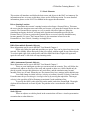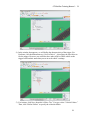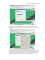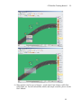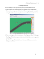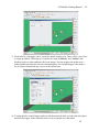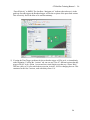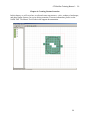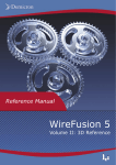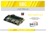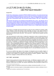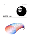
1
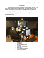
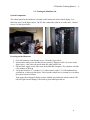
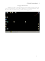
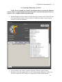
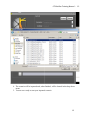
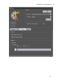
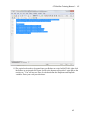
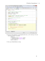
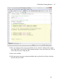
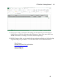
GT MiniSim Training Manual -‐ 1 Georgia Tech Psychology MiniSim Driving Simulator Training Manual Georgia Tech School of Psychology Tech Report GT-PSYC-TR-2015-01 Riley W. Winton, Thomas M. Gable, & Bruce N. Walker [email protected], [email protected] May 5, 2015 Sonification Lab School of Psychology Georgia Institute of Technology 654 Cherry Street Atlanta, GA, USA http://sonify.psych.gatech.edu Phone: +1-404-894-8265 Georgia Tech School of Psychology Tech Report GT-PSYC-TR-2015-01 GT MiniSim Training Manual -‐ 2 Introduction This training document seeks to train users in the operation of the MiniSim National Advanced Driving Simulator owned by the Georgia Tech Department of Psychology. The simulator is located in B72 of the J.S. Coon Psychology Building at Georgia Tech. Additional training information can be found from the system developer’s website: http://www.nads-sc.uiowa.edu/sim_minisim.php If you are using the MiniSim only to collect data or run participants for an existing study, you will only need to review chapters 1 and 2 (pages 4-23) for basic instruction on getting started. For more advanced information about editing existing scenarios or creating new maps/scenarios, please read chapters 3, 4, and 5 (pages 24-69). Georgia Tech School of Psychology Tech Report GT-PSYC-TR-2015-01 GT MiniSim Training Manual -‐ 3 Table of Contents Chapter 1: The Basics 1.1) 1.2) 1.3) 1.4) Equipment Turning the Simulator On Turning the Simulator Off Support Documentation Chapter 2: Running a Previously Created Driving Scenario 2.1) 2.2) 2.3) 2.4) Preparing & Importing the Scenario Running the Scenario Add Participant Numbers Simulator Sickness Protocol Chapter 3: Editing Driving Scenarios 3.1) 3.2) 3.3) 3.4) 3.5) 3.6) ISAT: Interactive Scenario Authoring Tool Opening a Scenario Basic Elements Creating and Editing Triggers Example Interactions Testing and Running in MiniSim Chapter 4: Creating Custom Scenarios 4.1) 4.2) 4.3) Opening a Scene Editing a Scene Transfer Changes into MiniSim Chapter 5: Handling Driving Data 5.1) 5.2) 5.3) 5.4) 5.5) 5.6) Extracting Driving Data NDAQ Tools Introduction Importing DAQ Files Viewing DAQ Data Analyzing DAQ Data Advanced NDAQ Tools Chapter 6: Going Forward with the MiniSim p. 4 p. 5 p. 6 p. 8 p. 9 p. 10 p. 11 p. 13 p. 15 p. 18 p. 24 p. 25 p. 26 p. 28 p. 30 p. 34 p. 38 p. 39 p. 40 p. 41 p. 43 p. 46 p. 47 p. 50 p. 51 p. 53 p. 57 p. 63 p. 69 Georgia Tech School of Psychology Tech Report GT-PSYC-TR-2015-01 GT MiniSim Training Manual -‐ 4 Chapter 1: The Basics This chapter will explain the different components of the system, where they are located, and how to interact with them. For more information, please see the MiniSim User Manual in the support documentation. 4 GT MiniSim Training Manual -‐ 5 1.1 Equipment The Driving Simulator covered in this document is referred to as the “MiniSim,” a high fidelity driving testing environment produced by NADS – the National Advanced Driving Simulator group from the University of Iowa. The system includes a quarter-cab of actual vehicle hardware including a steering wheel, pedals, adjustable seat, and shifter from a real vehicle. Additionally, LCD-based “glass dash” control and instrument panels, surround sound audio, three 42” flat panel displays, and a side-mounted touch-screen make this an extremely customizable testing platform for many types of driving interactions. The figure below shows the location of these elements. 1. 2. 3. 4. 5. 6. 7. 8. Adjustable Seat Steering Wheel Accelerator and Brake Pedals Gear Shifter “Glass Dash” Instrument Panel Display Panels Side-mounted driver touch screen NADS MiniSim Control PC 5 GT MiniSim Training Manual -‐ 6 1.2. Turning the Simulator On System Components The control panel for the hardware is located on the bottom left of the central display. It is labeled as area 1 in the figure below. The PC that controls the software is on the desk – labeled as area 2 in the figure below. Powering on the Hardware 1. Go to the hardware control panel in area 1 from the figure above. 2. Switch on the main power and fans for the system by flipping switch 1A as seen in the figure below – this is the red switch inside the white plastic case. 3. Flip the black toggle switch 1B to turn on the MiniSim computer. The computer will take a few minutes to boot up. 4. Verify that switches 1C-1 (audio), 1C-2 (wheel motor), and 1C-3 (LCD dashboard) are switched on, as shown in the figure. These switches should always remain on, even when the system is powered down. Turn on the three flat panel display screens with the gray Panasonic remote control. The red LED light on each display will switch to green when powered on. 6 GT MiniSim Training Manual -‐ 7 Starting the Software 1. When the computer is booted, start the MiniSim program by double clicking the steering wheel icon on the desktop. NOTE: If the mouse cursor is hidden, move the mouse all the way to the right until it is visible. The PC monitor and 3 displays are set up as an extended display, sometimes the mouse gets lost in the 3 large display screens. 2. Wait for the program to load – when ready, the NADS MiniSim Splash screen will be visible on the central TV screen. 3. You are now ready to run a scenario! 7 GT MiniSim Training Manual -‐ 8 1.3. Turning the Simulator Off 1. Turn off the MiniSim PC by clicking “Start – Shut Down “ just as you would normally shut off a Windows PC. 2. After the computer is completely shut down, flip switch 1A (the red switch in the white box) to power down the hardware. 3. Turn off the three TV displays with the Panasonic remote control. NOTE: DO NOT FLIP SWITCH 1A OR DO A HARD SHUT OFF WHILE THE PC IS STILL RUNNING – DATA WILL BE LOST! YOU MUST SHUT OFF THE PC FIRST! NOTE: DO NOT FORGET TO TURN OFF THE DISPLAYS; THEY MUST BE TURNED OFF WITH THE REMOTE. 8 GT MiniSim Training Manual -‐ 9 1.4. Support Documentation NADS has provided very thorough training documents including manuals, tutorials, and getting-started-guides for the various software and hardware involved with the MiniSim. All of these are located on the MiniSim desktop in a folder called “Support Docs.” 9 GT MiniSim Training Manual -‐ 10 Chapter 2: Running a Previously Created Driving Scenario Chapter 2 explains how to set up and run an existing scenario in the MiniSim. For more information, please see the MiniSim User Manual in the support documentation. 10 GT MiniSim Training Manual -‐ 11 2.1. Preparing & Importing a Scenario NOTE: Prior to running any scenario, participants must be screened for simulator sickness. This is a required protocol designed to protect vulnerable individuals. Please see section 2.4 for a complete walkthrough and details. 1. With the MiniSim software loaded, click the drop-down Scenario menu on the GUI and select your desired scenario. If your scenario is visible in the menu, you may skip to section 2.2 to run the simulation. 2. If your scenario is not visible, it must be imported. Click the “Import” button. 3. Navigate to where the scenario file is (*.scn) on the computer and select it. Most .scn files are located in the ISAT folder at C:\Program Files (x86)\NADS\Isat\data\ 11 GT MiniSim Training Manual -‐ 12 4. The scenario will be imported and, when finished, will be located in the drop-down menu. 5. You are now ready to start your imported scenario. 12 GT MiniSim Training Manual -‐ 13 2.2. Running a Scenario Please ensure that you have personally created any studies you wish to run. Do not alter or edit any previously existing scenarios – these may be involved in ongoing data collection. Always make a duplicate or backup of any scenarios you are using. If you are unsure, don’t touch it! If you are not collecting driving data, for example if you are testing a scenario or just using a placeholder task: 1. Open the MiniSim software. 2. Select your scenario from the drop-down menu. If it is not visible, go to section 2.1 to learn how to import scenarios. 3. Click the “Settings” tab and uncheck “Data Collection Mode” 4. Click “Start Drive” If you are collecting driving data: 1. Open the MiniSim software. 2. Click the “Settings” tab and check “Data Collection Mode.” See the figure below to see what this screen looks like. 3. Click the “DAQ” tab; select your desired experiment name and participant number. 4. Select your desired scenario with the drop-down menu at the top-right. 5. Click “Start Drive” to begin the scenario. NOTE: This is critical – if “Data Collection Mode” is selected, existing data may be overwritten! Please do not edit or mess with other user’s scenarios if you are unsure! NOTE: Sometimes, people accidentally leave the gear shifter in “Drive.” If this occurs, simply tap the brake pedal when starting a new scenario and the software will refresh to show the transmission in drive. 13 GT MiniSim Training Manual -‐ 14 14 GT MiniSim Training Manual -‐ 15 2.3. Adding Participant Numbers When in “Data Collection Mode,” the incoming data is automatically sorted by experiment and participant. For an existing study, this information will already be loaded. However, new scenarios must have this information created by editing a file called ExperimentConfig.txt. 1. Ensure that the MiniSim software is closed before editing! 2. Open ExperimentConfig.txt in Notepad by double clicking the desktop shortcut or navigating to C:/NadsMiniSim_v1.8.x/Data/Rcm_data/ NOTE: The configuration file is shared by all MiniSim experimenters. If you are unsure of your edits, please make a backup copy before changing anything. NEVER delete any existing experiment lines as these belong to other researchers. 15 GT MiniSim Training Manual -‐ 16 3. There are three columns in order from left to right: a. Experiment name b. Participant name/number c. List of allowable scenarios for each participant 4. Add a new line for each participant number in your experiment. Type the experiment name, then tab, then participant number, tab, then the scenarios allowed for that participant (separated by commas). For example if you wanted to create a new study for 10 participants where each can drive on both the “campus” or “CityDemo” scenarios, you would add the following new lines to the file: NewStudyName NewStudyName NewStudyName NewStudyName NewStudyName NewStudyName NewStudyName NewStudyName NewStudyName NewStudyName 01 02 03 04 05 06 07 08 09 10 campus,CityDemo campus,CityDemo campus,CityDemo campus,CityDemo campus,CityDemo campus,CityDemo campus,CityDemo campus,CityDemo campus,CityDemo campus,CityDemo Additionally, you can assign certain participants to specific scenarios, such as the example below where odd numbered participants can only drive the “campus” scenario and even-numbered can drive the CityDemo scenario. NewStudyName 01 campus 16 NewStudyName NewStudyName NewStudyName NewStudyName NewStudyName NewStudyName NewStudyName NewStudyName NewStudyName 02 03 04 05 06 07 08 09 10 GT MiniSim Training Manual -‐ 17 CityDemo campus CityDemo campus CityDemo campus CityDemo campus CityDemo 5. When finished, save the ExperimentConfig.txt file and close it. Note: When creating new study names try to make them easily understood as to who is using that study such as putting a lab name or experimenter name in the title. Also please do not modify other people’s lists, simply add your own. After you are done with the study, please go back and delete the names so the document does not become unreasonably long. 6. Start the MiniSim software; check “Data Collection Mode” and the new experiment and participant settings should be selectable. 17 GT MiniSim Training Manual -‐ 18 2.4. Georgia Tech Simulator Sickness Screening Protocol (GTSSSP) Occasionally, participants may exhibit signs of sickness, dizziness, weariness, and/or nausea from performing a driving scenario. To prevent participants from experiencing any kind of discomfort, a screening protocol has been developed by researchers at Georgia Tech. ALL PARTICIPANTS MUST BE SCREEN FOR SIMULATOR SICKNESS BEFORE COMPLETING ANY OTHER DRIVING RELATED TASKS IN THE MINISIM. The protocol consists of a pre-test to assess the participant’s current mood and feelings, a short ~2 minute drive through a virtual city, then a post-test to check for significant differences in mood after the drive. As with other studies, drivers should be informed that if they feel sick, nauseous, sweaty, or negatively affected in any way after they begin they drive, they can stop and remain seated until they feel comfortable enough to be debriefed. For more information on the research and establishment of the GTSSSP, please read the following source. Please cite this work in any studies where it is used: Gable, T.M. & Walker, B.N. (2013). Georgia Tech Simulator Sickness Screening Protocol. Georgia Tech School of Psychology Tech Report GT-PSYC-TR-2013-01. October 21, 2013. Accessible at: http://sonify.psych.gatech.edu/publications/simsicknessscreening/GTSSSP--GT-PSYCTechReport-2013-01.pdf Running the Pre-test 1. Turn on the PC located on the desk near the MiniSim PC monitor – this controls the Lilliput touch screen mounted next to the dashboard and a mirror of what is on that screen is shown on the second computer screen on the MiniSim desk. 2. There is a user account called GTSSSP that will be used for anyone doing the GTSSSP for the simulator. The password for this account is the same as the username - GTSSSP. 3. When booted, double click on “GTSSSP—Electronic-Survey-v1.1 – Shortcut” on the top right of the desktop. 18 GT MiniSim Training Manual -‐ 19 4. The Simulator Sickness Survey will open. Enter your experiment name and the current participant number, then click “Begin Survey.” 19 GT MiniSim Training Manual -‐ 20 5. Enter the participant’s age, gender, and number of years driving, then click “Continue Survey.” 6. At this point, the participant, seated in the cockpit, will use either a finger or the back of a pen to tap the touch screen and answer 17 questions about his or her current mood. 20 GT MiniSim Training Manual -‐ 21 7. When finished, a screen will announce that Part 1 is complete. Do not let the participant press “Continue” yet. 21 GT MiniSim Training Manual -‐ 22 Running the Driving Scenario During the drive, users should obey all traffic laws and signs as they normally would. Instructions will be shown on screen, but users can be informed that they will wait for two cars and then pull out and follow the lead car. 1. Start the MiniSim software. 2. Click the “Settings” tab and uncheck “Data Collection Mode.” 3. In the Scenario drop-down menu, select “GeorgiaTechSimulatorSicknessScreeningProtocol.scn” 4. Click “Start Drive.” 5. When finished, the drive will automatically end. Running the Post-test After the drive, participants will complete the second part of the survey in order to receive their simulator sickness screening score. 1. Once the drive has ended, tell the participant to tap “Continue” on the touch screen and answer the remaining 17 questions in the survey. 2. When finished, the survey will say, “Thanks! Survey complete.” 22 GT MiniSim Training Manual -‐ 23 3. The score is shown at the very end of the filename where it’s scored. In the example below, the user scored an 8. 4. If the user scores a 3 or higher, he or she likely suffers from simulator sickness and should not be allowed to continue with any driving-related study. 5. If the user scores a 2 or lower, he or she does not exhibit signs of sickness and can continue with the study. If he or she does report feelings of nausea, they can cease participation at any time. 6. For record keeping, the participant’s score and output are logged to the directory: C:/Users/Sonify/sickness-survey/yourexperimentname/participant.txt 7. The protocol is now completed. If the user is continuing with a driving study, restart the MiniSim software before proceeding. 23 GT MiniSim Training Manual -‐ 24 Chapter 3: Editing Driving Scenarios This chapter will explain how to get started with basic scenario editing. For more information, please see the ISAT User Manual in the support documentation. 24 GT MiniSim Training Manual -‐ 25 3.1. ISAT: Interactive Scenario Authoring Tool ISAT, the Interactive Scenario Authoring Tool, is software developed by NADS for creating and editing driving scenarios. The sections of this chapter will begin with basic operating procedures, important terms, and then end with how to transfer your developed scenarios into the MiniSim. For more information, please see the ISAT User Manual in the support documentation. To get started, double click the ISAT icon on the desktop of the MiniSim. A GUI will open with options to begin. 25 GT MiniSim Training Manual -‐ 26 3.2. Opening a Scenario 1) With ISAT running, click “File à Open” and select an existing .scn file that you want to edit. The default folder should contain all scenarios, but if not, navigate to “C:\Program Files (x86)\NADS\Isat\data” NOTE: ALWAYS CREATE A BACKUP COPY BEFORE EDITING AN EXISTING SCENARIO! 26 GT MiniSim Training Manual -‐ 27 2) When opened, you will be presented with an overhead map view of the scenario. All map area will be green, regardless of the texture being used. This means that no city buildings, landscaping, or special geographical features will be visible until running the scenario in the MiniSim. These features are placed into the maps or edited via the Tile Mosaic Tool explained in the next chapter. You can navigate over the map by using the following controls: Arrow keys Mouse scroll wheel Mouse right click/hold Mouse left click/hold Shift/Mouse hold/drag Space/Mouse hold/drag Move up/down/left/right Zoom in/out Zoom in to a selected area Select all objects in selected area Drag the screen around the map Measure the distance between two points 3) On the right, there is a list of elements that can be added for different types of driving interactions. These will be covered in detail in the following section. 27 GT MiniSim Training Manual -‐ 28 3.3. Basic Elements This section will introduce and define the basic terms and objects in the ISAT environment. For information on how to create or edit them, please see the following section. For more detailed information, please see the ISAT User Manual in the support documentation. Driver Starting Location: To determine the scenario’s starting location select Insert->External Driver. This turns the cursor into the insertion cursor and when you hit enter, will insert the External Driver into the scenario. The External Driver appears as a car (or truck) with all its lights on. When the simulation run begins, the driver will start in the location and orientation specified by the External Driver. It is best to position the External Driver on a road, since the simulation may become unstable if it is not. The External Driver is also sometimes referred to as the ExternalDriver, Own Vehicle, Ownship, or simply Driver. DDO (Deterministic Dynamic Objects): More information can be seen in the ISAT User Manual Chapter 4. DDOs only follow the path and speed they are given. They can be placed anywhere in the network. They blindly follow their path, at the given speed, without regard for any other objects. To set their path, right click on the model, and select Add Path Nodes. Right click again and again for each node. A left click will stop inserting nodes. ADO (Autonomous Dynamic Objects): More information can be seen in the ISAT User Manual Chapter 5. These are semi-intelligent cars that you can insert into the scenario. They will follow the road network, adhere to the rules of the road, and respond to other cars. ADOs should only be placed on roads, because their behaviors only work there, and the simulation may become unstable if they are off road. When they are first inserted, they have settings in their default state. You could change its initial velocity (velocity at creation), from the Velocity Control tab. From the same tab you can also give it a target velocity by moving the mph slider. This target velocity is the speed the ADO will attempt to maintain if road conditions allow. To specify the ADO's path, right click on the model, and select Extend Path. Then right click on the road network to create its path. The path has to be a route that the ADO could follow. Static Objects: These are objects or vehicles placed in the scenario that will have a visual representation at runtime but no other behavior. 28 GT MiniSim Training Manual -‐ 29 Coordinators: These are scenario objects, which coordinate actions between various scenario elements. Triggers are the main type of coordinators, but there are also Sources and the Traffic Light Manager. Types of Coordinators: Triggers These elements fire (perform some action) when their predicate is true. They are named by predicate type and multiple types occur. More information can be seen in Chapter 9 of the ISAT User Manual. Roadpad Trigger is one that is fired when the appropriate object drives over its road pad. Expression Trigger fires when a given expression is true. Time Triggers fire at a specified time Follow Triggers fire when their follow conditions are met. Traffic Light Triggers fire when the appropriate traffic light state occurs. Details of the firing conditions are authored from the trigger’s Predicate page. In the case of a Roadpad Trigger, you select the object that will drive over the trigger's roadpad. You can select it by name, type, or road. If you want the External Driver (human user) to trigger the action, choose By Type Set -> ExternalDriver. All trigger have the same set of actions which they can perform. They can do such things as create and object, delete an object, set a cell or variable, set a dial or button on an object, terminate the simulation, etc. One important consideration is the lifetime parameter of a trigger. This represents how long the trigger will last in the scenario. The default setting is lifetime, which means the trigger can fire and be reset an infinite number of times. However, if a specific script is important in the scenario, “One Shot” activation can be used to ensure the trigger fires only one time. The ISAT manual goes into details on all the trigger actions and how they are authored in Chapter 9. Source A source creates ADOs at specific locations, at regular intervals. These are used to generate additional road traffic. Traffic Light Manager The Traffic Light Manager is used to author each intersection’s traffic lights. The ISAT Manual gives details and examples of authoring with the Traffic Light Manager in Chapter 8. 29 GT MiniSim Training Manual -‐ 30 3.4. Creating and Editing Triggers 1) To create a trigger, select the type by clicking and holding it on the right-side panel, then drag it to the desired location on the map. In this example, we will create a road pad trigger that causes the user’s tire to blow out when crossed. 2) We will first add a visual indicator on the road so we can see it in the simulator. Drag a “traffic cone” or “drum” from the right elements panel onto the map just past the start direction. 3) Drag a Road-pad trigger from the elements panel anywhere off the road, near the drum or cone we just added. 30 GT MiniSim Training Manual -‐ 31 4) In the window that appears, we will define the characteristics of the trigger. For Predicate, click the button that says “Set Ext Driver” – this allows the user/driver to fire the trigger. However you could also have other ADO or DDO vehicle as the trigger based on their name that you set in each vehicle’s settings 5) For Actions, click New, then title it “Blow Tire.” For type, select “Vehicle Failure.” Then, click “Define Failure” to specify the vehicular failure. 31 GT MiniSim Training Manual -‐ 32 6) Many options exist, but for simplicity, we will select tire 0 to blowout in 0s, or immediately when the road pad trigger is crossed. Click OK until you are back at the map view. 7) Now that the trigger itself is defined, the final step that remains is to place the actual road pad trigger on the road. Right click the newly created trigger and click “Place Road Pad.” Click once to drop the start point, and again to drop the ending point of the road pad. This zone is the actual area where the predicate must occur. 32 GT MiniSim Training Manual -‐ 33 8) Many options exist for types of triggers – speed control, lane changes, traffic flow, traffic lights, etc. For more information, details, and sample scenarios, please visit the ISAT Manual. 33 GT MiniSim Training Manual -‐ 34 3.5. Example Interactions Here, we will analyze a basic trigger for loading start-up text and beginning a lead car. 1) In the screenshot below, ExampleScenario.scn is opened and zoomed into the External Driver location (starting location for driver’s car). When running the scenario, some initial text will give instructions to the user and perform some timing logic for holding a blue lead car in place until the scenario is ready. 2) There are two triggers visible in the starting area - a TimeTrigger and a Blue Car hold trigger. TimeTrigger: This loads start-up text and then releases the blue lead car when the appropriate time has elapsed. Blue Car hold trigger: This holds the blue car’s velocity at 0 MPH (stationary) until the loading text has vanished. 34 GT MiniSim Training Manual -‐ 35 3) The details for each trigger can be viewed by double clicking on it. There will be a set of tabs in a pop-up window. The majority of controls are in the “Predicate” and “Actions” tabs. Predicate refers to what condition will fire the trigger. For time triggers, the predicate is a defined global time that runs once the simulation starts. For road pad triggers, this means a list of certain elements that may cross over the defined area. 4) Viewing the blue car hold trigger predicate tab shows that the blue car lead is the only object that fires the trigger. In the action tab, there is one action that sets a dial titled 35 GT MiniSim Training Manual -‐ 36 “ForcedVelocity” to 0MPH. The checkbox “Instigator set” indicates that whoever is in the predicate list and triggers the Roadpad trigger will be the recipient of the prescribed actions. This effectively forces the blue car to remain stationary. 5) Viewing the TimeTrigger predicate tab shows that the trigger will fire at 0s, or immediately at the beginning. Viewing the “Actions” tab, one can see a list of 7 different actions that this trigger will fire. At 0s, Action 1 occurs and sets visual display text that says “Please Wait.” This has a delay of 1s, after which the next action, Action 2, will fire changing the text. This continues for the first 5 actions, each with delays from 1-5s. 36 GT MiniSim Training Manual -‐ 37 6) Action 6 removes the blue car hold trigger, then Action 7 resets the ForcedVelocity dial for the blue car, allowing it to accelerate to its predefined target velocity. 37 GT MiniSim Training Manual -‐ 38 3.6. Testing and Running in MiniSim When finished with edits, or if you want to check a specific interaction, you may use the ISAT Rehearsal mode. Select Mode->Rehearse, and the scenario will perform, as if it is being run on the simulator. You will see the ADOs and DDOs following their paths, you can see triggers fire, and traffic lights changing. The External Driver will behave as if it is an ADO, following the rules of the road and responding to other objects. The External Driver can be given a path, but it can’t be directed like an ADO. It can't be authored so that it changes lanes, or adjusts its speed. If you wish to test the scenario with behavior you expect of experimental subjects, you need to make a separate test scenario. Make a copy of your scenario, and replace the External Driver with a test ADO, giving it some unique name like “DriverTest.” Then author that test ADO so that it drives in the way you expect of the driver. You can use triggers to modify its speed, change lanes, stop, etc. Then modify the triggers that are to be fired by type, ExternalDriver, so that they are instead fired by Name, “DriverTest.” If you wish to do a complete test in the actual simulator, simply save a new version of the scenario in ISAT, import it like any other scenario, and then run it in the MiniSim. 38 GT MiniSim Training Manual -‐ 39 Chapter 4: Creating Custom Scenarios In this chapter, we will cover how to edit and create map textures – cities, roadways, landscapes, and other similar features, for use in driving scenarios. For more information, please see the NADS TMT Tile Mosaic Tool Guide in the support documentation. 39 GT MiniSim Training Manual -‐ 40 4.1. Opening a Scene 1) To edit the visual scenes, a separate software program called the Tile Mosaic Tool is used. To get started, double click the icon on the desktop. 2) Open the example scene called “simple_rural” by clicking File à Open, then navigate to C:\NADSTMT_1.7.5.2\ProjectData\Databases\simple_rural\simple_rural1 3) You will be prompted to open some files for pre-processing. Select “Preprocess.” When loaded, you will see on overview tile map of the scene. This one consists of a circular track with two spurs in the center. 40 GT MiniSim Training Manual -‐ 41 4.2. Editing a Scene 1) With a scene loaded, its properties can be adjusted by clicking “File à Properties.” 2) Additional tiles can be dropped in from the menu on the left (seen in the figure below). The categories include: Campus City Commercial Filler Freeway Industrial Mountain Railroad Residential Rural Urban Special Suburban 41 GT MiniSim Training Manual -‐ 42 3) To add a tile, select a category and pick a specific tile. Click it, then click on the map in the location you want the tile to fall. 4) By default, tiles are locked after being placed. To unlock, right click on a tile and click “Lock/Unlock Selected Tile(s).” After this, the tile can be moved, rotated, or further adjusted. 5) When constructing your scenario, verify that all tile pieces match edges. This helps with performance and reduces the chance of graphical errors/glitches. Please see the TMT Manual page 4 for more information. 6) When finished, save your work. 42 GT MiniSim Training Manual -‐ 43 4.3. Transfer Changes into MiniSim 1) When finished designing your scene, you need to export your changes into ISAT. Do this by clicking “Output à Scenario/Visual Data.” 2) The default directories should be correct, but verify that it’s the same directory and the scene you’re currently working on. 3) Check the “Output BLI File” option – this is what’s needed to import into ISAT. 43 GT MiniSim Training Manual -‐ 44 4) Click OK to begin the output process. 5) A command prompt will appear on the far left TV screen showing the completed output process, move the mouse to the far left and click it then press any key to dismiss it. 6) When finished, you will have a .bli file ready for use in ISAT. 44 GT MiniSim Training Manual -‐ 45 7) Open ISAT, click “File à New” and select your newly created .bli file. You now have a blank scenario where you can add traffic, obstacles, and interactions. Be sure to save the .scn file. At this point, the scenario can be imported and run in the MiniSim normally. 45 GT MiniSim Training Manual -‐ 46 Chapter 5: Handling Driving Data This chapter covers how to extract, process, compute, and handle driving data from the MiniSim’s DAQ files. More information can be found in the nDAQ Tools tutorial document in the support documentation. 46 GT MiniSim Training Manual -‐ 47 5.1. Extracting Driving Data If you recently ran a driving experiment in “Data Collection Mode,” the MiniSim will have generated a set of *.DAQ files that contain all of the data about the user’s driving behavior. To access these files: 1) Click “Start à Computer.” 2) Open the D: Drive titled “MiniSim_Data.” 47 GT MiniSim Training Manual -‐ 48 3) Open the “DAQ” folder, then open the folder with your experiment’s name. 4) The folders inside each experiment correspond to the participant numbers. In this example, we will open participant 1 from an “Example Scenario” experiment. 48 GT MiniSim Training Manual -‐ 49 5) In the chosen folder, you will see a set of .DAQ and .txt files. The filename is organized by experiment name, scenario name/number, and a timestamp. 6) Select all of the .DAQ files and copy them to a flash drive or external hard drive. The .txt files are just logs and most likely won’t be needed for analysis. You are now ready to analyze the data with NDAQ tools. 49 GT MiniSim Training Manual -‐ 50 5.2. NDAQ Tools Introduction NADS has developed a tool for exploring, condensing, and analyzing driving data from the MiniSim’s output DAQ files – this is called NDAQ tools and is based on MATLAB. Use of NDAQ tools requires a licensed MATLAB installation. How to install NDAQ Tools: 1) Ensure your PC has a valid version of MATLAB running. Versions 7.12.0 (R2011a) and above are supported. 2) Find the ndaqTools folder from the support documentation. It should contain several folders, a README.txt file, and a setpath.m MATLAB script. 3) Copy the ndaqTools folder into your MATLAB folder tree – by default this is located at C:\Users\*yourusername*\Documents\MATLAB\ Note: Processing DAQ files in MATLAB often takes several minutes per DAQ file. If you wish to cancel a reduction in process, simply click MATLAB’s command window and press CTRL+C. 50 GT MiniSim Training Manual -‐ 51 5.3. Importing DAQ Files 1) On the MATLAB PC, navigate to C:\Users\*yourusername*\Documents\MATLAB\ and create a new folder with your experiment’s name as the title. Inside this folder, create two additional folders – one called “DAQData” and the other called “DataReduction.” As an example, we have created an “ExampleScenario” folder with the required subfolders. 2) Insert your flash drive or external hard drive with the DAQ files you copied from section 5.1 into to computer with NDAQ Tools installed. 3) Copy the DAQ files into the new DAQData folder you just created. 51 GT MiniSim Training Manual -‐ 52 4) You are now ready to begin viewing and analyzing your data. 52 GT MiniSim Training Manual -‐ 53 5.4. Viewing DAQ Data 1) Open MATLAB. 2) In the Current Folder panel, navigate to your MATLAB folder – by default this is at C:\Users\*yourusername*\Documents\MATLAB\ 3) In the MATLAB command window, type “DaqViewer” and press Enter. 4) A new GUI will appear – on the top right of it, click “Open DAQ File” and navigate to your recently copied DAQ files, then select one of them. 5) The panel on the right will be populated with all of the variable names recognized in the file. 53 GT MiniSim Training Manual -‐ 54 6) Click the Read DAQ Vars button to read the file into memory. After the data is read (it might take a while; you should see a progress update in the MATLAB command window), you will see that the Plot Data button becomes active. 54 GT MiniSim Training Manual -‐ 55 7) You can now scroll through the list window on the right, select a variable, and click Plot Data to view it in a figure. You can also see information regarding that variable in the bottom left area of the GUI. 55 GT MiniSim Training Manual -‐ 56 56 GT MiniSim Training Manual -‐ 57 5.5 Analyzing DAQ Data NDAQ Tools is a powerful but daunting looking piece of software with many scripts and files that have to be organized correctly. This section will explain how to set up all parameters to run a reduction and analysis on your DAQ files. For advanced instruction on how to define or compute parameters, see section 5.6 on Advanced NDAQ Tools. 1) 2) 3) 4) Open MATLAB. Change the working folder to the …\*yourexperiment*\DataReduction folder you created earlier. In the MATLAB command window, type “NdaqBasic” and press Enter. Four new files will be copied to the directory: Analyze.m, go.m, Reduce.m, and setup.xls. Open the newly created “setup.xls” spreadsheet. This is where you will define the measures that you wish to extract from your data. It is the specification for your reduction. You should see this small table on the first sheet: DaqName DaqPath The name of the DAQ file The path of the DAQ file string string The first column is a list of your measure names. The second column is a description, or definition, of your measures. The third column contains the units of the measures. This spreadsheet is more than a specification. It is actually loaded by the reduction script and used to locate measures and insert them in the desired column of the reduction. Think of each row in the specification as a column in the final reduction. If you change the order of two rows in the first, the order of the columns in the output also change. Functionally, the 57 GT MiniSim Training Manual -‐ 58 only column of the specification that matters is the first, the names. The others can be deleted, redefined, or rearranged and it won’t affect the reduction script. Add as many driving measures as you want now and save the file, they will be imported later. 5) Open the configuration for the reduction. Do this by typing “ExpConfig” in the MATLAB command window and pressing Enter. 6) A new GUI will pop up. Here, we will configure the data reduction and analysis. 7) Select the path to your DAQ files on the top right. 8) For Reduction script, click change and select the Reduce.m file we just created. 9) For Analysis script, click change and select the Analyze.m file we just created. 10) Change your Reduction Settings if so desired. You can interpolate your daq data to a common frequency, which is 60 Hz by default. In a raw daq file, not all variables are necessarily collected at the same rate; and interpolating them makes it easier to code the 58 GT MiniSim Training Manual -‐ 59 reduction script. You can skip calling the reduction script (Reduce.m) by checking the Skip Reduction button. Similarly, you can skip the analysis by checking the Skip Analysis button. 11) Specify the Matlab Files convention. The first open uses the run name, which is a common method for NADS studies. The run name is obtained from the folder name in which each daq file resides. If you do not take care to design a folder tree for your daq files, or each daq file is not in a folder of its own, then you will want to select the second option, Use Daq Name. This means that a mat file with the same name as the daq file will be created as the daq files are first read. Subsequent runs of the reduction script will load the data from the mat file instead of the daq file, which can result in a speedup of 10X or more. 12) Specify the Data Reduction Setup by clicking the file dialog button and choosing the setup.xls spreadsheet. Its name should show up in the text field. You won’t need it right away, but click the Create Matlab Script button to generate a short script that you will insert into your Reduce.m script later. 13) Set the Reduction Output by typing a name for the reduction spreadsheet in the text field. A date/time stamp will be appended to this name if you check the Add Date/Time button. Selecting the Incremental button will do two things. First, the disposition spreadsheet (discussed later) will be automatically modified to indicate that a daq file has been reduced. Second, the output spreadsheet will be incrementally updated after each file is reduced. 14) Create your Disposition Spreadsheet. This spreadsheet will consist of a list of all the daq files in your experiment. By appropriately placing X’s in one of the first four columns of the spreadsheet, you can control which files are reduced and which are ignored. An incremental reduction will automatically move the X from the first column (Analyze) to the second (Reduced) as the reduction is running. In order to create it, type the name of the file in the text field, something like ‘DAQ.xls’ and be sure to press the enter key. Then click the Create button to automatically search your daq file folders and add them to the disposition spreadsheet. 15) Create an Element List. Make a DAQ Element List if so desired. Daq files have a lot of extraneous information in them. This makes it take longer to load them, and makes it harder to find the variables you’re interested in. Using an element list, you can specify only the variables that you are interested in for the reduction. Click the Create button to open up the DaqViewer GUI, shown below. Click the Open Daq File button and select one of the daq files from your experiment. You should see a list of grayed-out variables (elements) in the list window; and the Create Cell List button should become active. 59 GT MiniSim Training Manual -‐ 60 16) Click the Create Cell List button and another GUI will open, shown below. Select as many elements as you wish and add them to the right list. You can also remove ones you have selected back to the left list. When you are done, click the save button and name the element list file something like elemList.mat. You can now close the Create Cell List and DaqViewer GUIs. Back on the ExpConfig GUI, in the DAQ Element List section, click the file dialog button and select the element list file you just created. 60 GT MiniSim Training Manual -‐ 61 17) Save your work! Use the File menu at the top of the GUI, select Save and type a name for your configuration file, a mat file. It is recommended to use a simple and generic name, such as config.mat. 61 GT MiniSim Training Manual -‐ 62 18) Click the Save and Run button to save the configuration and run the reduction. If it asks you to pick the configuration file, select the config.mat file. It will take a while to process, normally several minutes per DAQ file depending on the size. 19) Congratulations! You have just run your first reduction. A file called Output_*timestamp*.xls should have been created in your experiment folder. If you open it, you will see that each DAQ only contains the DAQName and DAQ Filepath – this is because there were no other parameters defined in the Reduce.m script. The next section will cover how to get your desired parameters to be computed and placed in the output spreadsheet. 62 GT MiniSim Training Manual -‐ 63 5.6. Advanced NDAQ Tools The last section covered how to configure an analysis and get all of the supporting files in place. However, when you ran it, no data was in the output file! This is because you defined your driving measures in the setup.xls, but never incorporated them into the script. This section will explain how to get all of your data into the output. 1) In your experiment’s DataReduction folder, open the setup.xls spreadsheet. 2) As an example, let’s add three new measures called measure1, measure2, and measure 3. You may wish to describe each one and define the type of variable, but they can be left blank if you are unsure. Save the file and close it. 3) In MATLAB, change the working folder to your experiment’s MATLAB folder, then type “ExpConfig” in the command window and press Enter. 4) Load your existing configuration by clicking File à Load, and select “Config.mat” – this is the file you created at the end of the previous section. 5) On the right, in the Data Reduction Setup panel, Select your setup.xls spreadsheet and click “Create Matlab Script.” A new window with some MATLAB code will appear. 63 GT MiniSim Training Manual -‐ 64 6) The only coding that needs to be done is to define the parameters. You can call on any DAQ variable that you selected when you created the “Element List” in the previous sections. You can output it directly or do some calculations on the variable including average, standard deviation, maximum, minimum, etc. 7) As an example, let’s make measure1 and measure2 the average and standard deviation of the steering wheel angle. This is done by creating an array of the average and standard deviation all in one line of code. One of the utility functions in nDaqTools is called BasicStats and returns several basic statistics functions after removing any potential NaN values from the signal. The usage in the case would look like: [str_avg, str_sd] = BasicStats(elemDataI.CFS_Steering_Wheel_Angle); 8) Let’s make measure3 the percentage of time that the speed is above 50 mph. We can use the nDaqTools function Percentage for that calculation, written as: pct_speeding = Percentage(elemDataI.VDS_Veh_Speed>50); 9) Then call on these new variables in the SetResults commands like so: r = SetResults(r,header,'measure1',str_avg); r = SetResults(r,header,'measure2',str_sd); r = SetResults(r,header,'measure3',pct_speeding); 10) Select all of the code and copy it to the clipboard. 64 GT MiniSim Training Manual -‐ 65 11) The copied code needs to be pasted into your Reduce.m script. In MATLAB, right click the Reduce.m script and click Open. Scroll to the bottom section titled “write data to the results row,” You will see two lines of code that define the DaqName and DaqPath variables. Paste your code just after those. 65 GT MiniSim Training Manual -‐ 66 12) You may notice that there are some duplicate lines now, so let’s clean it up. You can delete four of the lines you pasted: results = []; r = SetResults(r,header,’DaqName’,NaN); r = SetResults(r,header,’DaqPath’,NaN); results = [results; r]; 13) Save your finished Reduce.m script. 66 GT MiniSim Training Manual -‐ 67 14) Now you simply need to rerun your reduction. If you created a config.mat file, simply type “ExpConfig” into the MATLAB command window, press enter, then click “File à Load” and select your config.mat file. 15) Press Save and Run. 16) After processing, open your output spreadsheet and you should see the three calculate measures that you coded! 67 GT MiniSim Training Manual -‐ 68 17) You are now ready to commence with coding your full reduction. Several scripts in nDaqTools are useful for calculating reduced measures. Some of the more useful ones include: BasicStats, Percentage, Percentile, and SteeringEntropy. 18) NADS is happy to help you get started with your reduction and help you find or develop scripts that may meet your needs. You can contact them via the information below: Chris Schwarz National Advanced Driving Simulator [email protected] 319-335-4642 (o) 319-621-1042 (c) 68 GT MiniSim Training Manual -‐ 69 Chapter 6: Going Forward with the MiniSim While this tutorial serves as a beginner’s guide to getting driving experiments up and running in the MiniSim, there are naturally many other advanced methods, techniques, and tips for implementing sophisticated studies. This section attempts to merely mention several concepts to provide inspiration for future studies. -‐ Workload and cognitive load can be assessed with NASA TLX or other custom surveys. They can be administered with the touch screen mounted next to the dashboard or via a laptop, other desktop, or paper and pencil. -‐ Physiological data can be measured alongside behavioral data via heart rate, eye tracking, or other advanced methods. Please speak to the department or your lab supervisor for information on getting started. -‐ Secondary tasks such as cell phone activity can be simulated with smartphones for distracted driving studies. -‐ More advanced data collection can occur with telemetry and CAN (controller area network) hardware for more precise data collection. -‐ Of course, many other ideas and technologies exist. If you wish to design or develop your own, please get in contact with the department to schedule some time in the simulator. Please keep in mind this is a shared departmental resource. NEVER DELETE ANY FILES OR MAKE ANY SYSTEM CHANGES unless the department has approved it and/or the files are yours. Please be mindful when using the simulator and many other parties have a vested interest in the continued operation of the system. 69