1
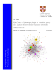
MORO: A Cytoscape Plugin for Relationship Analysis between Modularity and Robustness in Large-Scale Biological Networks Cong-Doan Truong,1 Tien-Dzung Tran,2 and Yung-Keun Kwon1,* 1 School of Computer Engineering and Information Technology, University of Ulsan, 93, Daehak-ro, Namgu, Ulsan 680-749, South Korea. 2 Department of Information Technology, Center for Research and Development, Hanoi University of Industry, Hanoi, VietNam. User Manual A. How to setup ........................................................................................................................... 2 B. How to use .............................................................................................................................. 3 I. Setting ..................................................................................................................................... 4 1. Setup OpenCL options.......................................................................................................... 4 II. Single Network Analysis ......................................................................................................... 4 1. Load Single Network Analysis panels .................................................................................. 4 2. Import a network .................................................................................................................. 5 3. The relationship between network dynamics and modularity ................................................ 7 a. Set update-rules perturbations and states of nodes ............................................................. 7 b. Whole network robustness examination ............................................................................ 8 c. Module detection .............................................................................................................. 8 d. In-/Out-module robustness examination ............................................................................ 8 4. Module visualization and displays of robustness and centrality value ................................... 8 a. Module visualization ......................................................................................................... 9 b. In-/out-module robustness and centrality values of each module ..................................... 10 c. Whole network robustness .............................................................................................. 10 III. Batch-mode analysis.............................................................................................................. 11 1. Load Batch-mode Analysis panel ....................................................................................... 11 2. Generate a network............................................................................................................. 11 3. Network dynamics analysis ................................................................................................ 12 4. Module detection ................................................................................................................ 12 5. Batch-mode case study ....................................................................................................... 12 -1- A. How to setup - After executing the Cytoscape, choose Apps parent menu->Apps Manager. Then, a window will appear as a figure below - Next, click the button “Install from File” to select the jar file (MORO.jar) to install the MORO plugin. OpenCL setup: o Download "Accelerated Parallel Processing (APP) SDK" from AMD website http://developer.amd.com/ (recommended version is v2.8), and install it. - -2- o - B. Install appropriate drivers for all Graphics cards of the computer. Download example network files from http://mo-ro.sourceforge.net/ for a test. Note: Run the Cytoscape software with an Administrator permission (for example, in Windows 7, a user can right-click on the icon of Cytoscape and choose "Run as administrator"), because MORO needs a permission to write result files in some functions. How to use We explain how-to-use by using a case study based on the following networks: - - HSN (for Single Network Analysis ) o The human signal transduction network with 5,443 nodes and 37,663 links after removing neutral interactions from the original dataset (version 4) downloaded from www.bri.nrc.ca/wang o Use the file “HSN.txt” STKE (for Single Network Analysis) o STKE consists of 754 proteins and 1,624 interactions after removing all neutral interactions from the integrated network by using the 51 canonical pathways (not specific to any organism or cell type) obtained from http://stke.sciencemag.org/ o Use the file “STKE.txt” Usage of MORO will be demonstrated by following sections: I. Setting 1. Setup OpenCL options II. 1. 2. 3. 4. Single Network Analysis Load Single Network Analysis panels Import a network The relationship between network dynamics and modularity Module visualization and displays of robustness and centrality value 1. 2. 3. 4. 5. Batch-mode Analysis Load Batch-mode Analysis panels Generate a network Network dynamics analysis Module detection A Batch-mode case study III. -3- I. Setting 1. Setup OpenCL options - Choose Setting... menu - OpenCL Setting menu has three main options: o CPU with one core: only use one core of the CPU for tasks o OpenCL on CPU multi-core: use all cores of the CPU for parallelization of tasks o OpenCL on GPU device: use GPU device for parallelization of tasks II. Single Network Analysis 1. Load Single Network Analysis panels - Run Cytoscape, and MORO plugin will be automatically loaded in Plugins menu of Cytoscape as following: - Choose Single Network Analysis This mode has a main control panel: o For the relationship between network dynamics and modularity analysis -4- 2. Import network - Imported networks can be a pre-generated RBN, signalling or regulatory network. o Note that: To import networks in this plugin, the networks file must have at least 3 columns, source node, interaction type and target node where the interaction type only can be one of -1, 1 and 0 that are corresponding to inhibition, activation and neutral, respectively. For example, a small part of STKE network is shown as follows: - By using the built-in import function of Cytoscape, users can select a file in some formats and users have to specify which column is a source, a target and an interaction type. - Next, in case of STKE.txt file, unselect the option (“space”) and check the option (“Transfer first line as column name start import row”). On the other hand, in case of HSN.txt file, select the option (“space”) and check the option (“Transfer first line as column name start import row”). -5- For example: The result of STKE network is shown as follows when we choose “Organic” in the Layout/yFiles menu. -6- 3. The relationship between network dynamics and modularity Control panel The correction between network dynamic and network modularity can be examined based on a set of initial state. Here, we provided an option below: Note that: - The number of initial states should be larger than 0 value and smaller than or equal to all possible number of states (2n value: n is equal to a number of nodes of network). However, it is very time-consuming to analyse the network robustness with all possible number of states in large-scale networks such as HSN or STKE. Therefore, we used 2n initial states to investigate the correction between network modularity and network robustness such as whole network, in-/out- module robustness. Actually, the outcome of 2n initial states is approximately similar to the result of 2n initial states because the numbers of found attractors are not much different to each other. - On the other hand, if the network size is not so large (in general, the number of nodes <20), we can examine all possible initial states. a. Set update-rules perturbations and states of nodes Each node in the network has its own state and update-rule. Thus, before executing the network dynamics analysis, users have to set update-rules and states of nodes. Right after a network is either generated or imported, update-rules and states of all nodes are randomly assigned. But, users can specify them manually. Regarding update-rules, we provide three updating-rule schemes; CONJ-DISJ, CONJ, and DISJ. o If CONJ-DISJ is chosen, users can either specify or randomize update-rule for each node. o Note that, 1 and 0 denote disjunction and conjunction, respectively. Users also can either specify or randomize state for each node. o Note that, 1 and 0 denote “on” or “off” state, respectively. In visualization Nodes having state 1 and 0 are represented by gray and light-gray colors, respectively. Nodes having conjunction and disjunction update-rules are represented by rectangle and circle shapes, respectively. The state and update-rule of each node is also stored as node attributes, and they are updated whenever they are changed either by setting values in Node Attribute Browser Tab manually or simulation of network dynamics. The figure below shows an example of a small network, CDRN. -7- Node Attribute Browser b. Whole network Robustness Examination After setting the update-rule and the number of states, we can examine the whole network robustness. More specifically, ( ) is the robustness against initial-state perturbation and ( ) is the robustness against update-rule perturbation. The results will be shown on the table in panel. In the next section, we will show the results more detail c. Module detection After the whole network robustness is examined, the module detection algorithm (Leicht and Newman, 2008) is used to find all modules of a network and the modularity is calculated by using an optimization algorithm proposed in a previous study (Noack, 2009). In the next section, we will show the result of all modules in network and three types of module visualization. d. In-/Out- Module Robustness Examination After all modules are found, in-/out module robustness ( ( ) and ( )) can be examined by using the Hamming Distance. The detailed results will be shown in the next section. 4. Module visualization and displays of robustness and centrality values The below figure shows the main interface of module visualization and results displays of robustness and centrality values. Part (1) is used to setup parameters before module visualization. Part (2) shows the robustness and centrality values of each module. Finally, Part (3) shows the analysis results about the whole network. -8- a. Module visualization - There are three options for module visualization, namely detail mode, absolute mode, and relative mode - In the Inhibiting (-) and Activating (+) items, we can activate them for displaying interactions of network. If no options are selected, network will not show any type of links. - First progress bar with a caption “Appearance Ratio (%)” is used to limit the percentage of interactions of network which will be shown on the window. - Second progress bar with a caption “Edge width (%)” is used to control the size of edge of network. - Final progress bar with a caption “Node Size (%)” is also used to control the size of nodes of network. - Moreover, we can choose the modules to be displayed by checking the boxes as follows. First, the below figure is the result of the detail mode. Second, the below is the result of the absolute mode. Finally, the below is the result of the relative mode. -9- -Note that: label of edge denotes the ratio of the number of interactions between a pair of modules to the maximal possible number of interactions between them; that is, /( ) , where is the number of actual interactions between the pair of modules, and and are the numbers of nodes included in each of the modules b. In-/out- module robustness and centrality values of each module This figure shows the detailed results of each module. More specifically, some values of each module are number of nodes, number of edges, in-module robustness against initial-state perturbation, in-module robustness against update-rule perturbation, out-module robustness against initial-state perturbation, and out-module robustness against update-rule perturbation. we also provide five centrality measures including degree (Jeong, et al., 2001), closeness (Wuchty and Stadler, 2003), betweenness (Freeman, 1977), stress (Shimbel, 1953), and eigenvector (Bonacich, 1987). Finally, the export button will export the result to a text file. c. Whole network robustness This figure shows the summary result including the number of nodes, the number of edges, the robustness against initial-state perturbation, the robustness against update-rule perturbation, the modularity value, the number of modules, the in-module robustness against initial-state perturbation, the in-module robustness against update-rule perturbation, the out-module robustness against initialstate perturbation, and the out-module robustness against update-rule perturbation. Besides, this result will be saved to a text file by using the export button. - 10 - III. Batch-mode Analysis 1. Load Batch-mode Analysis panel - Choose the menu Plugin/MORO/Batch-mode Analysis This mode has only one main control panel: - Analysis of Network dynamics and modularity can be performed by three following steps: o Step 1: Random Boolean Network generation o Step 2: Network dynamics o Step 3: Network's modularity There is an option for saving results: o Choose “Save detailed results for each node of all networks” if users want to save two types of robustness results of each node of all random networks. Three next sections will describe details of the above steps. - - 2. Generate a network - Step 1: Random Boolean Network generation: o Choose one of random Boolean network models Barabási-Albert model (Barabási and Albert, 1999), Erdős-Rényi model (Erdös and Rényi, 1959), Erdős-Rényi variant model (Le and Kwon, 2011) Shuffling model (Maslov and Sneppen, 2002) o Choose parameters to generate corresponding random Boolean networks o For the first three models, users can set the probability of negative link's assignment (this probability would affect the ratio of negative links to all links). o For Shuffling model: create random networks from a given network. Choose "Shuffle direction and sign of all interactions" if users want to create random networks by shuffling the direction and the sign of every interaction from the given network: Shuffle I. Choose "Preserve in-degree and out-degree of all nodes" if users want to create random networks by rewiring the edges of the given network such that the in-degree and the out-degree of all nodes are conserved: Shuffle II. Users can set the value of "Shuffling intensity" parameter. The number of rewiring steps = Shuffling intensity × (number of edges). o Choose "Don't create view for random networks" if users don't want to create view for random networks when the simulation is running. If this option is selected, MORO can save a significant amount of memory. - 11 - 3. Network dynamics analysis - Step 2: Network dynamics: calculate robustness against initial-state perturbation and update-rule perturbation over a chosen set of initial-states o Choose a update-rule scheme for each node of all random networks: CONJ and DISJ: denote that each node of a random network would be assigned a conjunction and disjunction function, respectively. CONJ-DISJ: denotes that each node of a random network would be assigned a conjunction or disjunction function randomly. o Choose “Robustness against Initial-state mutation” if users want to calculate robustness against initial-state perturbation value of each node of all random networks. o Choose “Robustness against Update-rule mutation” if users want to calculate robustness against update-rule perturbation value of each node of all random networks. 4. Module detection - 5. Step 3: Network's Modularity: Module algorithm is applied to find all module of network. Finally, all results will be saved to text files. Batch-mode case study In this section, we present a case study for the new function of MORO: batch-mode simulation on RBNs. A previous study (Tran and Kwon, 2013) showing that modularity and dynamic-related robustness are negatively correlated significantly. Here, we use the batch-mode function to validate the correlation between them. First, the network files of HSN and STKE are needed to be imported into Cytoscape software. Next, we execute two RBNs simulations by using the batch-mode function. To this end, we choose shuffling techniques for the simulations: - Shuffle II for the first simulation o "Shuffling intensity" parameter is set to 4 For a simulation, we set some following parameters: - Number of random networks: HSN is 100 random networks and STKE is also 100 random networks - We recommend users to check the option "Don't create view for random networks" to save a significant amount of memory. We also recommend users to setup OpenCL options for faster simulations by the parallelization of examining robustness Second, BA model is used to generate 6,400 random networks with | | = 50 and49 ≤ | | ≤ 2,031. Result of simulation is shown in the following two figures. - 12 - (a) (b) Figure 1. (a) Modularity and (b) robustness of the real HSN and STKE signaling networks, compared with those of random Boolean networks. The Random(HSN) and Random(STKE) results were taken from 100 random Boolean networks that were generated by shuffling interactions of the HSN and STKE networks while preserving their degree distribution, respectively. (a) Modularity results. The modularity values of HSN and STKE were computed to be 0.54778 and 0.73071, respectively. On the other hand, the mean ± s.d. results of the modularity in the Random(HSN) and Random(STKE) groups were 0.38095 ± 0.06758 and 0.55145 ± 0.05248, respectively. The modularities of the real signaling networks were significantly larger than those of the random Boolean networks (p-value < 10−4). (b) Robustness results. The robustness values of HSN and STKE were computed to be 0.74967 and 0.672, respectively. On the other hand, the mean ± s.d. results of robustness in the Random(HSN) and Random(STKE) groups were 0.75282 ± 0.00078 and 0.68028 ± 0.00346, respectively. The robustness values of the real signaling networks were significantly smaller than those of the random Boolean networks (pvalue < 10−4). - 13 - (a) (b (c) ) (d) (e) Figure 2. Correlations between the modularity and robustness of 6400 random Boolean networks generated with | | = and ≤| |≤ . (a) Relationship between network modularity and robustness: the correlation coefficient was negative (R = −0.80303, p-value < 10−4). The results for HSN and STKE, denoted by the rectangular and triangular points, respectively, were very close to the linear regression line. (b–e) Contributions of in-module/out-module robustness to the relationship between network modularity and network robustness. (b) Relationship of the network modularity to the in-module robustness (R = −0.30383, p-value < 0.0001). (c) Relationship between network modularity and out-module robustness (not significant). (d) Relationship of the network robustness to the in-module robustness (R = 0.27801, p-value < 0.0001). (e) Relationship between network robustness and out-module robustness (not significant). - 14 - References Barabási, A.-L. and Albert, R. (1999) Emergence of Scaling in Random Networks, Science, 286, 509-512. Bonacich, P. (1987) Power and Centrality: A Family of Measures, American Journal of Sociology, 92, 11701182. Erdös, P. and Rényi, A. (1959) On random graphs, I, Publicationes Mathematicae (Debrecen), 6, 290-297. Freeman, L. (1977) A Set of Measures of Centrality Based on Betweenness, Sociometry, 40, 35-41. Jeong, H., et al. (2001) Lethality and centrality in protein networks, Nature, 411, 41-42. Le, D.-H. and Kwon, Y.-K. (2011) NetDS: a Cytoscape plugin to analyze the robustness of dynamics and feedforward/feedback loop structures of biological networks, Bioinformatics, 27, 2767-2768. Leicht, E.A. and Newman, M.E.J. (2008) Community Structure in Directed Networks, Physical Review Letters, 100, 118703. Maslov, S. and Sneppen, K. (2002) Specificity and Stability in Topology of Protein Networks, Science, 296, 910-913. Noack, A. (2009) Modularity clustering is force-directed layout, Physical Review E, 79, 026102. Shimbel, A. (1953) Structural parameters of communication networks, Bulletin of Mathematical Biophysics, 15, 501-507. Tran, T.-D. and Kwon, Y.-K. (2013) The relationship between modularity and robustness in signalling networks, Journal of The Royal Society Interface, 10. Wuchty, S. and Stadler, P.F. (2003) Centers of complex networks, Journal of Theoretical Biology, 223, 4553. - 15 -